Ultra-Fab Powermover PM5900 User manual

!" #
$%&'(
)("*"+,'+
-.%%,$$'
/.%%,+%
0*.!0&!&1* &23# 0
&*&.3# 0

1
INTRODUCTION
Dear Customer
Congratulations and thank you for purchasing a Powermover by Ultra-Fab. It is our
intent to provide you with the best possible product we can build, backed up by excellent
customer service.
We realize, as with any power equipment, that the user of our products will need assistance
from time to time. Please feel free to call or fax our customer service department. Our
technicians are eager to serve you in any way possible. Phone: 800-860-7571 Fax: 800-860-
4980 E-mail customerservice@ultra-fab.com Web site: www.ultra-fab.com
Please take time to read and understand your operation manual before putting your Powermover
into service. Please follow the service guide lines set forth in the manual to ensure the best
possible care of your Powermover. Failure to perform the necessary maintenance on a timely
basis could result in unnecessary repairs and customer dissatisfaction.
Please remember we appreciate your business and are here to serve you.
Sincerely
Darryl Searer/President

2
TABLE OF CONTENTS
BASIC OPERATION
Warning-------------------------------------------------------------------------------------------------------3
Keyed Switch-------------------------------------------------------------------------------------------------3
Variable Speed Control------------------------------------------------------------------------------------3
Forward & Reverse-----------------------------------------------------------------------------------------3
Hydraulic Switches------------------------------------------------------------------------------------------3
Brake Control------------------------------------------------------------------------------------------------3
Braking--------------------------------------------------------------------------------------------------------3
Charging System---------------------------------------------------------------------------------------------3
Steering--------------------------------------------------------------------------------------------------------4
Hydraulic Lift------------------------------------------------------------------------------------------------4
Hour Meter---------------------------------------------------------------------------------------------------4
Options--------------------------------------------------------------------------------------------------------4
Safety Recommendation-----------------------------------------------------------------------------------4
GENERAL MAINTENANCE
Motors---------------------------------------------------------------------------------------------------------5
Grease Fittings-----------------------------------------------------------------------------------------------5
Batteries-------------------------------------------------------------------------------------------------------5
Hydraulic Fluid Level--------------------------------------------------------------------------------------5
Chains--------------------------------------------------------------------------------------------------------- 5
Tires------------------------------------------------------------------------------------------------------------5
REPLACING PARTS
Recommendations-------------------------------------------------------------------------------------------5
Motors---------------------------------------------------------------------------------------------------------6
Belts------------------------------------------------------------------------------------------------------------6
Shaft 3 ---------------------------------------------------------------------------------------------------------6
Tires------------------------------------------------------------------------------------------------------------7
Chains----------------------------------------------------------------------------------------------------------7
Differential----------------------------------------------------------------------------------------------------7
Hydraulic Pump---------------------------------------------------------------------------------------------7
Hydraulic Cylinders----------------------------------------------------------------------------------------7
PARTS BREAKDOWN
WIRING DIAGRAMS

3
BASIC OPERATION
WARNING
Your Powermover was designed to move heavy objects and loads on nearly level surfaces.
Do not operate on slopes.
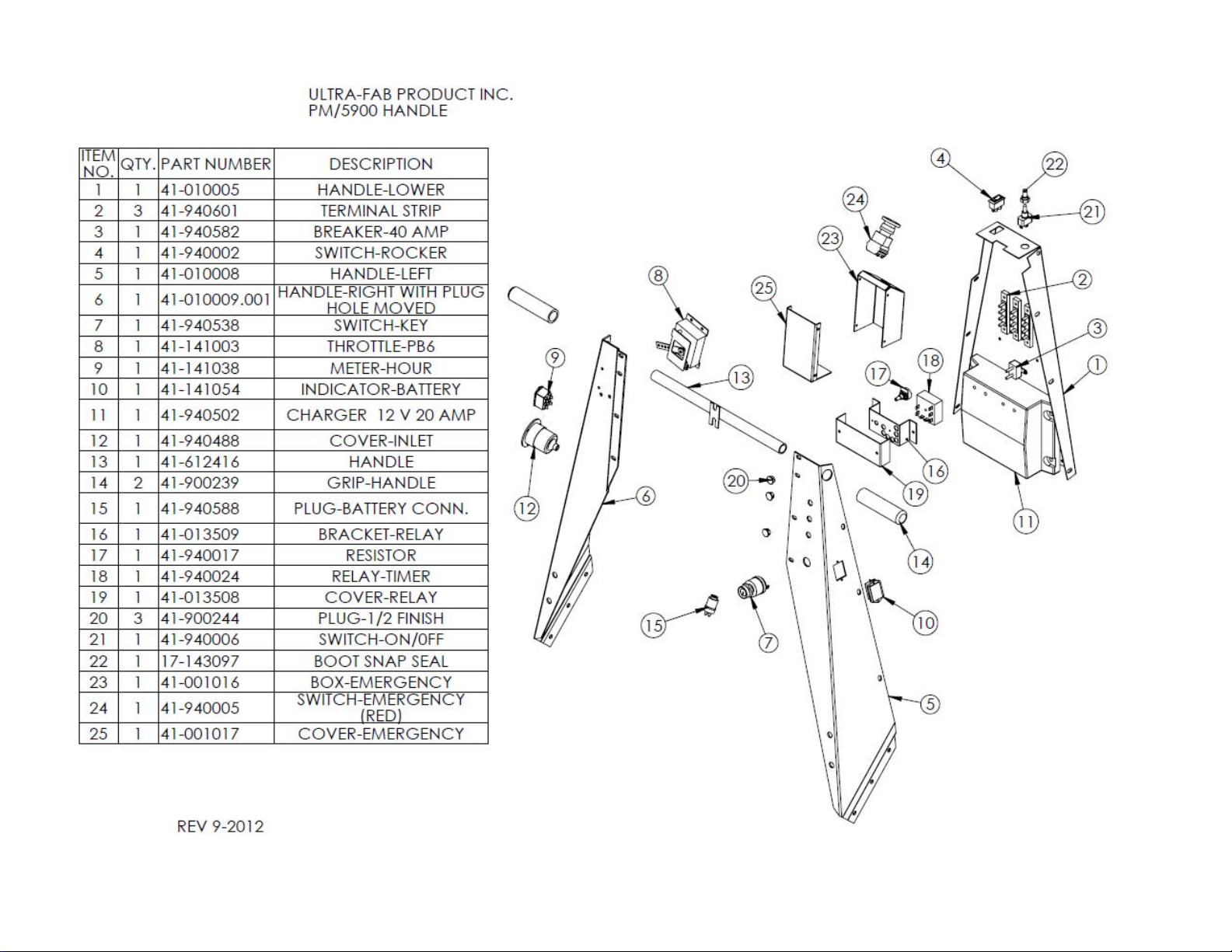
KEYED SWITCH
Your Powermover requires a key to turn the ignition switch on. Be sure to turn the key to the off
position when your Powermover is not in use.
VARIABLE SPEED CONTROL
The speed control is operated with the right index finger and has a one second delay built into it. When
you pull the speed control lever you will hear a click and experience a short delay before the
Powermover begins to move. Do not pull the speed control lever to its maximum position until you get
the feel of how the Powermover accelerates. The procedure should be slow at first and then faster as
you become more experienced. Caution: Before pulling the speed control lever be sure the
forward/reverse switch is in the desired position.
FORWARD/REVERSE SWITCH
This is a simple rocker type switch and can be operated by using your right thumb. Caution: Make
sure you have selected the desired direction before activating the switch.
HYDRAULIC SWITCH (OPTIONAL)
Your Powermover may be equipped with a hydraulic lift. If it has a lift there is a switch on the handle to
control the up/down motion of the mast. Pull back on the switch to raise the mast and push forward on
the switch to lower the mast. Note: The switch is spring-loaded and requires you to hold the switch on
until the mast reaches the desired height.
BRAKE CONTROL (OPTIONAL)
If your Powermover has the seven way connector mounted on the top front of the Powermover, then
it has a push button switch on the handle to activate the receptacle. This button is used to activate the
trailer brakes if they are plugged into the standard seven way connector allowing the trailer brakes to
stop the load.
MAGNETIC BRAKING ¾ HP PERMANENT MAGNETIC MOTOR (Standard PM5700)
The ¾ hp motor, with its standard hookup, will brake the Powermover, when the speed control is
released with a three second delay. There is an emergency button that allows the unit to brake
immediately when pushed.
MAGNETIC BRAKING 2HP CONTINUOUS DUTY MOTOR (PM 5900)
The continuous duty motor, with its standard hookup, will brake the Powermover, when the speed
control is released with a three second delay. There is an emergency button that allows the unit to brake
immediately when pushed.
CHARGING SYSTEM
Your Powermover is equipped with a built-in-charging system. It requires a standard three prong
extension cord to use the battery charger. The male end plugs in to a standard 120 volt outlet and the
female end plugs into the receptacle located on the right of your Powermover. When your Powermover
is not in use you should leave the charger plugged in. When you first plug your charger in you will see a
red light come on. This is normal. When the batteries are near a full charge you will see a red and a
green light. When the red light goes out and only the green light is on you have reached a full charge. It
will not damage the batteries to leave the charger plugged in. You also have a battery level indicator
that will show the amount of charge left in your battery. It is located on the handle of your Powermover.

4
STEERING
Your Powermover is equipped with a steering handle that turns the Powermover when pushed to the
right or left. There is a caster under the rear of the PowerMover that swivels as you turn.
CAUTION: WHEN FIRST LEARNING TO OPERATE THE POWERMOVER SLOW AND
EASY IS THE BEST POLICY FOR BOTH THE SPEED CONTROL AND THE STEERING
CONTROL. USE SLOW SPEED WHEN MAKING TURNS.
HYDRAULIC LIFT
The hydraulic lift option is designed to provide traction for moving heavy objects by transferring some
of the weight from the object being moved to the front drive wheels of the Powermover. This transfer of
weight is essential to move many of the heavier objects. It also provides a quick way to attach to the
load.
HOUR METER
The hour meter is standard equipment on every Powermover as of June 1, 2001. We suggest you keep a
log book so you know the proper time to service your Powermover. The hour meter is located in the
handle. OPTIONS
HYDRAULIC LIFT
See paragraph on hydraulic lift.
WEIGHT KIT
Sometimes it is necessary to add weight to move certain loads, especially on non-hydraulic lift models.
A variety of weights are available to assist where needed.
FOAM FILLED TIRES
It is highly recommended to foam fill the tires. It adds weight. Allows the tires to carry a heavier load.
Prevents flat tires from occurring.
NON MARKING TIRES
Gray non marking tires are available for the Powermover.
ATTACHMENTS
Many jobs require some type of special attachment. We custom make whatever is necessary to do the
job. The following standard brackets are available. J-type hooks, pintle hooks, hitch balls, hitch pins, o-
rings and saddles. The attachments are adjustable to fit almost any need.
SAFETY SWITCH
The reversing safety switch is located on top of the handle and is designed to activate if you are backing
up and it hits your belly. When the switch hits your belly it will depress the switch, which immediately
reverses the motor. It is not possible to go backwards when the switch has been activated until you reset
the switch. You reset the switch by turning it clockwise. You will hear a click and see the switch pop out
to its normal set position. You will now be able to go in reverse.
SAFETY RECOMMENDATION:
IT IS RECOMMENDED THAT WHEN LIFTING A LOAD WITH THE HYDRAULIC LIFT
THAT YOU ONLY LIFT IT HIGH ENOUGH TO CLEAR THE GROUND SURFACE AND
THEN MOVE THE LOAD. SHOULD YOU FEEL UNCOMFORTABLE WHILE MOVING
THE LOAD YOU CAN QUICKLY LOWER IT TO THE GROUND.

5
GENERAL MAINTENANCE
2 HP MOTOR (PM5900)
CONTINUOUS DUTY: This powerful motor is designed for continuous use. It is a permanent magnet
motor and acts as a brake when the speed control is released. Its bearings are factory sealed and require
no maintenance; the brushes should be checked every 500 hours of operation.
GREASE FITTINGS
Shafts (grease every 1000 hours of operation)
1) 1 at the rear shaft (differential)
2) 1 at the front swivel caster (option)
3) 1 at the rear steering wheel
BATTERIES
Check the electrolyte level in each of the battery cells to be sure they are ½” above the top of the lead
plates. Caution: Never let the electrolyte drop below the top of the lead plates and never smoke or
have an open flame near the batteries. A spark or open flame could cause an explosion causing
injury.
HYDRAULIC FLUID LEVELS (optional)
Check the hydraulic reservoir at least every 150 hours. If it is low bring the level back up to the full
mark. Also check the hose and fittings at the same time for any fluid leaks.
CHAINS
Lubricate the chains once every year with motorcycle chain type grease.
TIRES (optional foam filled)
Your Powermover may have foam filled tires. This allows for the tires to carry more weight, adds
weight and prevents flat tires.
REPLACING PARTS
RECOMMENDATION
It is recommended that only certified mechanics replace most of the parts on your Powermover.
Ultra-Fab stocks any and all parts necessary to keep your Powermover in good operating condition
allowing for the best possible service. Many of the parts are self explanatory and very easy to replace.
The parts breakdown will show you where these parts go but does not explain how to change because it
is obvious.
NOTE: SHOULD YOU HAVE ANY QUESTIONS CALL ULTRA-FAB AT 800-860-7571

6
MOTOR
STEP 1) Open the door to battery compartment and disconnect the negative leads on the battery terminal
(2 places) This eliminates all power to the motor and the handle.
STEP 2) Remove the top cover by removing the six screws. Disconnect the two wires from the motor
terminals.
STEP 3) Loosen and remove the four bolts on the motor mount plate on the floor of p/m and lift the
motor up and out of its location. (The belt will come off the drive sheave as you remove the motor and
mount plate).
STEP 4) To reinstall reverse steps 1-3. The mounting plate has adjustments from side to side and well as
up and down. Install the motor in a way that the belt tracks true from pulley to pulley, this is achieved
with the side to side adjustments, and then adjust the belt tension with the front to back adjustments.
COG TYPE BELT (ON ALL MODELS BUILT AFTER (6/1/05) (Shaft # 1)
A cog type belt is used to drive the power from the motor to a large cog type sheave on the shaft #1.
You can replace the belt with out disassembling the unit. To replace the cog belt follow these steps.
STEP 1) Follow the first 2 steps above on replacing the motor.
STEP 2 ) Release belt tension on the motor. To achieve this loosen the 4 bolts holding the motor mount
plate. Allow the motor to slide forward in the elongated slots, this will loosen the belt.
STEP 3) Inside the housing locate the bearing block next to the cog pulley, you will see two (2) set
screws, loosen or back off the set screws, DO NOT remove them.
STEP 4) On the outside of the housing (belt side) , remove the access plate (4 5/16 bolts) the bearing
block will come off with it.
STEP 5) With the access plate removed you can remove and install a belt with out dismantling the gears
and pulleys.
STEP 6) Replace the access plate and tighten up the set screws on the inside bearing block.
STEP S7) Adjust the tension on the belt by pushing the motor back in the elongated slots, this will
tighten the belt, secure it to the frame by tightening the 4 bolts. (note check that the belt runs true before
replacing covers)
STEP 8) Replace covers
STEP 9) Reconnect batteries
SHAFT 3
STEP 1) Remove the chains, then the ½” bolts from side flange bearings. Lift out shaft.
STEP 2) To reinstall, insert shaft and ½“ bolts but do not tighten. Install the chains, to tighten the chains
loosen the lock nut at the adjuster bolt and tighten the adjuster bolt against the bearing block. (move
both sides the same to keep the shaft straight in relation with the other shafts) tighten the ½” bolts then
the lock nuts at the adjustment bolts.

7
FRONT DRIVE TIRES
To change a tire is just like a car. Remove the lug nuts and the tire and wheel will pull straight out and
off.
CHAINS
Adjustment of the chains is accomplished by loosening the bolts securing the bearing block to the frame,
and then adjusting the tightening screw. This will push the bearing block and tighten the chain and keep it from
moving when you are pulling a heavy load. Once the chains are tensioned lock down the bearing blocks, buy
securing the bolts. To remove or replace the chain, you must first identify the master link by rotating the chain
until you see the master link. Then use needle nose pliers to remove the keeper and pull the chain apart. You
can now reverse the steps and put the master link back together.
DIFFERENTIAL (Shaft # 2)
The differential is installed in your Powermover to allow one wheel to stand still or go backwards while
the other wheel goes forward during a turn.
Step 1) Remove the chains that go around the sprockets on the shaft. See “chains” above.
Step 2) Remove the 4 bolts that hold both the right and left flange bearings (2 each) and lift the
differential out of the main body.
Step 3) Transfer the bearings, sprockets, spacers and lock collars to the new differential shaft making
sure they are back in the same order as on the old shaft.
Step 4) Reverse steps 1-4 and make sure all bolts are tight.
HYDRAULIC PUMP
STEP 1) Remove cover top plate.
STEP 2) Disconnect hydraulic hoses (prepare for leakage of hydraulic fluid)
STEP 3) Disconnect wires.
STEP 4) Remove the 2 bolts holding the pump to the main chassis. Easily accessed on the left side of
the chassis.
STEP 5) Install new pump and reverse steps 1-4. Then check the hydraulic fluid level in the reservoir to
make sure it is at the proper level. There is a line showing where the level should be.
STEP 6) It will be necessary to operate the cylinder all the way up and all the way down to purge the air
from the lines. NOTE: You may need to do this procedure more than once to clear the air from the
lines.
HYDRAULIC CYLINDER
STEP 1) Remove the pin that holds the shaft of the hydraulic cylinder to the inner mast.
STEP 2) Remove the inner mast by pulling it straight up and out of the outer mast.
STEP 3) Disconnect the upper and lower hoses.
STEP 4) Remove cylinder and replace with new one.
STEP 5) Reverse steps 1-4 and add the proper amount of hydraulic fluid to bring the level up to the full
line.
STEP 6) It will be necessary to purge the lines of air. Do this by operating the cylinder to a full up and
then down position. You may have to do this procedure more than once to get all the air from the lines.


!
"
#
##$#
%&%$
##$"###
&$
%$
%&%$

!
" #$
$
"%&&
"&#&$
%$#$#!
&$

!
"#
"#
$"$#
$"$#
%#"#"!
%#"#"!
&&#'&&&

!"#
$#
$" " #
"#

!"#$#%"&'()!*+),
-$.-/
, 0/, , 12
-$3-1
2$--3
2-$
---
2/-1 2/-14
12/-1
223
24
.2525.--
56 56
56 56
325-
.--525

!"#
!$
%&'

Battery
Battery
Controller
DC88
Solenoid
Motor
24V
Pump
+
-
+
-
PM5900
Chassis Wiring
Rev: 12/2012
1
2
3
4
5
6
7
8
9
10
11
12
B+
B-
1
2
3
M-
A2
White
Yellow
Orange
B+
B-

Red +
Battery
Black -
Emergency
Stop
Brake
Forward/Reverse
Switch
PB 6
Throttle
Hour
Meter
Keyed
Switch
Battery
Level
Ind.
Battery
Charger
Charger
Inlet
Relay
1
2
3
4
5
6
7
8
9
10
11
12
Battery + 3
Battery - 4
Solenoid 7,8,9
Controller 10,11,12
Hyd. Lift 1,2
Circuit
Breaker
PM5900
Handle Wiring
Diagram
Resistor
White
Orange
Yellow
Orange
Gray
2
4
4
21
14
13
22
Rev: 12-2012
Lift Switch
(Optional)
White
3
2
1
1
Table of contents
Popular Utility Vehicle manuals by other brands

Taylor-Dunn
Taylor-Dunn B0-254-48 Operation, t roubleshooting and replacement parts manual

Swisher
Swisher COMMERCIAL PRO RC14544CPKA owner's manual

Axis
Axis E1 owner's manual

Second Wind Trailers
Second Wind Trailers FREEDOM Faq

Muck-Truck
Muck-Truck E Truck Owner & operator instruction manual

Humbaur
Humbaur 7000 Series Operating instruction

Toro
Toro TX Platform installation instructions

woodmizer
woodmizer ST Safety, Operation, Maintenance & Parts Manual

Ezgo
Ezgo ST SPORT Owner's manual & service guide

Valor
Valor 12-TU owner's manual

Taylor-Dunn
Taylor-Dunn C0-425-48 Service and Replacement Parts Manual

Club Car
Club Car Carryall 295 2007 owner's manual