Ultra A3380 User manual

S
EQUENTIAL
T
HERMOSTATIC
S
HOWER
V
ALVE
O
WNER’S
G
UIDE
These instructions cover all exposed or concealed versions of the
Sequential Thermostatic Shower Valve Models
ISSUE 02
Shower
Control
Handles and
Concealing Plate
may differ depending
on Model

2
INTRODUCTION
This owner’s guide shows you how to install, maintain and generally get the most from
your sequential thermostatic shower valve.
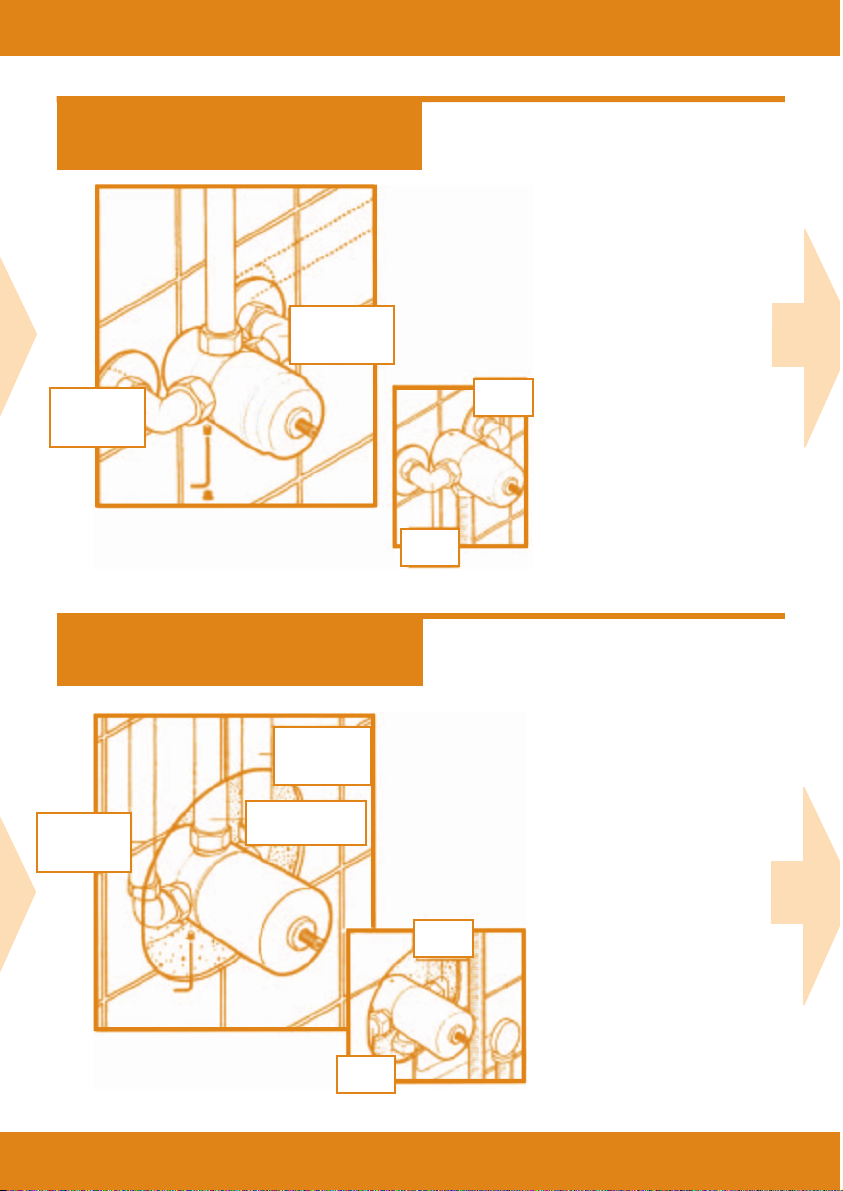
WE RECOMMEND INSTALLATION BY
A QUALIFIED PLUMBER ONLY
TECHNICAL DATA
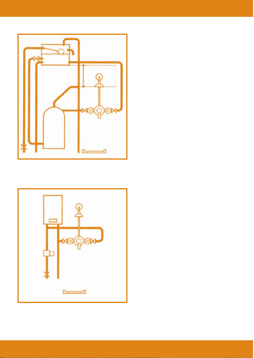
This shower valve is suitable for use on all common types of plumbing systems including gravity, pumped
and fully modulating combination boilers and high pressure unvented systems.
Minimum operating pressure 0.1 bar.
Maximum operating pressure 4 bar.
Important note: At static water pressures above 4 bar, you must install a pressure reducing valve in the mains
supply pipe set at 3 bar for optimum results.
As a guide to see if your water pressure is too high simply measure how many pints of water you get from your
kitchen tap, with the cold side fully turned on. If you exceed 8 pints (or equivalent) in 30 seconds then you require
a pressure reducing valve fitting to your incoming mains supply pipe immediately after stopcock to premises
.
TEST DATA
These valves have been pressure tested to 15bar.
Before proceeding, please note:
1. The valve must be installed in compliance with local water authority byelaws and water
supply byelaws.
2. Read all the instruction manual before proceeding
3. Only begin the installation when you have all the necessary tools ready.
4. Please check that all the components are in the shower valve box.
AFTERCARE
When installing or using tolls, extra care must be taken to avoid damaging the finish or the fitting. To
maintain the appearance of this fitting, please ensure it is cleaned regularly using a clean soft damp cloth
only. Abrasive cleaners or detergents must not be used as they may cause surface deterioration.
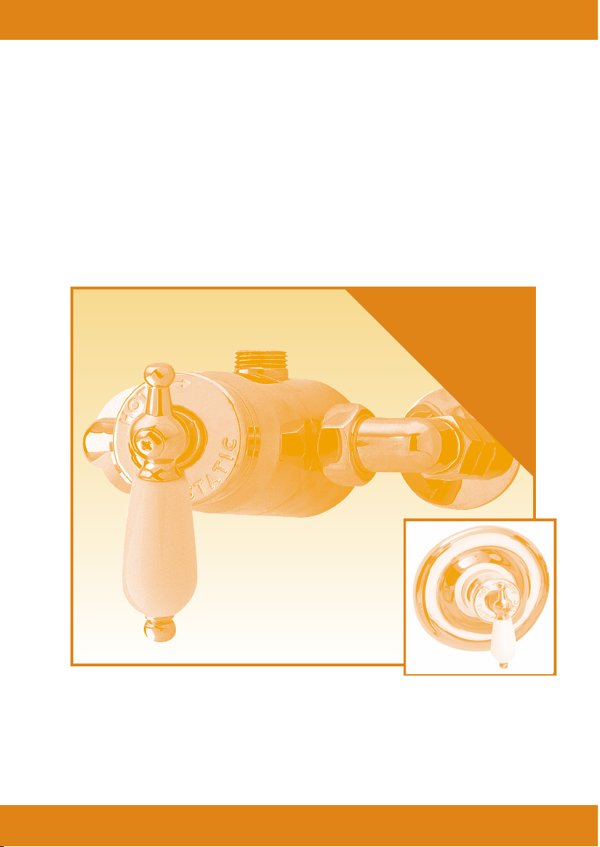
SEQUENTIAL THERMOSTATIC SHOWER VALVES
This shower valve uses a wax thermostatic cartridge to maintain a constant shower temperature. The valve is
anti-scald and will automatically shut down the shower if the cold water supply fails. The single sequential
control allows the shower to turn on at fully cold, further anti-clockwise movement will gradually blend in the
hot water up to a maximum showering temperature of a factory preset 43C when the shower valve is fully
opened (this may vary with certain installations).
You must ensure that the temperature of your hot water is at least 60°C for your shower to
reach the maximum temperature.
S
EQUENTIAL
T
HERMOSTATIC
S
HOWER
V
ALVE
Owner’s
Guide

3
EXPOSED VALVE Contents Check List
CONCEALED VALVE Contents Check List
Checklist may vary slightly depending on model supplied
Concealing Flange
Wall peg
Screws
(not supplied)
Engraved plate
and “O” ring
Handle
Handle
Screw
Valve body
Blanking plug
Allen Key
Grub screw
Elbow
Non-return
valve
Olive
Nut
Wall peg
Nut
Non-return
valve
Elbow Allen Key
Grub screw
Valve body
Engraved plate
and “O” ring
Handle
Screw
Handle
Grommet
Filter Washer
Concealing Plate
S
EQUENTIAL
T
HERMOSTATIC
S
HOWER
V
ALVE
Owner’s
Guide
Olive
Filter Washer

S
EQUENTIAL
T
HERMOSTATIC
S
HOWER
V
ALVE
Owner’s
Guide
4
EXPOSED VALVE Dimentions
CONCEALED VALVE Dimentions
57.5 mm
130 mm
100 mm
114 mm
57.5 mm
130 mm
92 mm
100 mm
114 mm
PRE-INSTALLATION
NOTES
for EXPOSED and
CONCEALED VALVES
•
Identify and check all the parts
(shower control handles
and concealing plate styles
may differ depending on
model).
•
When positioning the shower
valve, ensure you have sufficient
pressure for an acceptable
shower.
•
The hot water feed must always
be connected to the left hand
inlet of the shower valve as
viewed from the front, with the
shower outlet at the top.
•
Both hot and cold supply feeds
must have accessible isolator
valves fitted in-line for servicing
purposes (not supplied).
•
Refer to plumbing diagrams for
further installation guidelines.

S
EQUENTIAL
T
HERMOSTATIC
S
HOWER
V
ALVE
Owner’s
Guide
5
INSTALLATION NOTES
ON HOT WATER SYSTEMS
PLUMBING DIAGRAMS
Flat operated valve
Sequential shower
mixing valve
Isolator valve
Pressure reducing
valve
Stop cock
Twin impeller
pump
Overflow pipe

S
EQUENTIAL
T
HERMOSTATIC
S
HOWER
V
ALVE
Owner’s
Guide
6
GRAVITY FED SHOWERS
The shower valve must be fed from a
cold water storage tank and a hot water
cylinder. The use of a Surrey or Essex
flange connection to the hot water
cylinder will ensure an independent
supply of hot water to the valve; this
action will stop air being drawn into the
system.
N.B. Keep all pipework runs as short as
possible for maximum shower
performance.
N.B. Wherever possible 22mm
pipework should be used.
GAS HEATED/COMBI-BOILER
SHOWERS
The shower valve must be installed with a
modulating type combi-boiler or multi-
point gas water heater. This system will
produce a constant flow of water within
the operating specifications of the
appliance.
N.B. The outlet temperature of the system
must be capable of supplying hot water
in excess of 60°C.
A pressure reducing valve may be
required to ensure that cold water
pressures do not exceed 4 Bar static.
1 metre head
minimum

S
EQUENTIAL
T
HERMOSTATIC
S
HOWER
V
ALVE
Owner’s
Guide
7
UNVENTED MAINS PRESSURE
SHOWERS
The shower valve can be used on an
unvented mains pressure system. This
type of system must only be installed by
a competent person as per the
requirement of Part G of Schedule
1 to the building regulations.
For systems with no cold water take off
after the heaters pressure reducing valve,
an additional pressure reducing valve
must be fitted, and set, at the same
pressure as the heaters.
The water supply pressure to the shower
valve must be between 1 and 4 Bar.
PUMPED SHOWERS
The shower valve can be used on a
gravity fed pumped system. The use of a
Surrey or Essex flange connection to the
hot water cylinder will ensure an
independent supply of hot water to the
valve; this action will stop air being
drawn into the system.
N.B. Please follow pump manufacturers’
instructions relating to the sitting and
water feed details to the pump. Keep all
pipework runs as short as possible for
maximum shower performance.
N.B. Wherever possible 22mm
pipework should be used.

S
EQUENTIAL
T
HERMOSTATIC
S
HOWER
V
ALVE
Owner’s
Guide
8
•
Ensure hot and cold supply pipe feeds
are positioned correctly ready to
connect to the shower valve inlet
elbows.
•
If a rigid riser kit is being used, ensure
the valve is positioned correctly to take
the height of the vertical pipe.
•
Position the wall peg and secure to the
wall by means of two suitable screw
fixings (not supplied).
•
Both hot and cold supply feed must be
flushed through before connection to
the shower valve is made. Re Water
Supply Byelaw 55.
•
To create a waterseal, use a thin line of
suitable sealant around the supply pipe
feeds and the tiles
•
Fit the concealing flanges over the
supply pipes.
EXPOSED VALVE
Site Preparation
15mm
Connection to
Cold Supply
15mm
Connection to
Hot Supply
•
Make a cavity in the wall to allow the
hot and cold water supply connections
to be made.
•
Position the wall peg and secure in the
wall cavity by means of two suitable
screw fixings (not supplied)
•
Both hot and cold supply feed must be
flushed through before connection to
the shower valve is made. Re Water
Supply Byelaw 55.
CONCEALED VALVE
Site Preparation
15mm
Connection to
Cold Supply
15mm
Connection to
Hot Supply
Swivel Connection
to outlet
Depth
50/80mm
Maximum
160mm dia. hole

S
EQUENTIAL
T
HERMOSTATIC
S
HOWER
V
ALVE
Owner’s
Guide
9
See
Page
11
See
Page
10
•
Connect the hot and cold water supply
feeds to the shower valve using swivel
connector.
•
Fit the shower valve to the wall peg and
secure by tightening the grub screw
using the Allen key provided.
Fit blanking plug.
•
Make connection to shower
outlet, using swivel connector.
•
Check for any leaks.
EXPOSED VALVE
Site Preparation
CONCEALED VALVE
Site Preparation
For use with flexible hose, the
sequential thermostatic shower
valve should be installed with the
connection in the downward
position.
It must be remembered that the
location of the hot and cold water
inlets will be reversed.
(see illustration left)
•
Connect the hot and cold water supply
feeds to the shower valve, using swivel
connector.
•
Fit the shower valve to the wall peg and
secure by tightening the grub screw
using the Allen Key provided.
•
Make connection to shower outlet,
using swivel connection.
•
Check for any leaks.
N.B. Please ensure that the area around
the concealed valve is not filled in.
Access must be left for servicing
purposes.
The sequential thermostatic
shower valve can be installed with
the connection in the downward
position. It must be remembered
that the location of the hot and
cold water inlets will be reversed.
(see illustration left)
15mm
Connection to
Cold Supply
15mm
Connection to
Hot Supply
Hot
Supply
Cold
Supply
15mm
Connection to
Cold Supply
15mm
Connection to
Hot Supply
Swivel Connection
to outlet
Hot
Supply
Cold
Supply

S
EQUENTIAL
T
HERMOSTATIC
S
HOWER
V
ALVE
Owner’s
Guide
10
•
Place Grommet within the concealing
plate centre and push the plate into
position
N.B. A mild soapy solution
around the inside of the
Grommet will ease fitting.
•
To create a waterseal, use a thin line of
suitable sealant between the
concealing plate and the wall.
CONCEALED VALVE
Fit Concealing Plate
•
Fit the engraved plate and position
correctly (not included on all models)
•
Fit the shower control handle (shower
control handle and concealing plate
may vary depending on model).
•
Check the function of the valve.
The maximum temperature should be
43°C; if not, see Fault Finding chart at
the back of this guide.
CONCEALED VALVE
Final Assembly

S
EQUENTIAL
T
HERMOSTATIC
S
HOWER
V
ALVE
Owner’s
Guide
11
(Continued from page 9)
•
Fit the engraved plate and position
correctly (not included on all models).
•
Fit the shower control handle
(Style may vary depending on model).
•
Check the function of the valve.
The maximum temperature should be
43°C; if not, see Fault finding chart at
the back of this guide.
EXPOSED VALVE
Final Assembly
•
Set the shower to the hottest setting (anti-clockwise)
•
Ensure the shower is running
•
Remove the handle
•
Locate the Allen key down the spindle
•
The Allen key will locate onto a grub screw
•
To increase the temperature turn the Allen key
1
/
4
of
a turn anticlockwise, leave for 10 seconds to allow
temperature to stabilise
•
Repeat the process if the temperature is not sufficient.
Note, the Allen key should not go through more than
2 full turns or 8 x _ turn increments
•
If the shower valve does not get up to a minimum of
43°C, this suggests a problem with the incoming cold
supply pressure. Please refer to Fault Finding Chart.
TEMPERATURE ADJUSTMENT
The maximum temperature of the shower valve has been factory pre-set at 43°C, if for any
reason you wish to adjust the maximum temperature, please follow these instructions:
TO INCREASE THE PRESET TEMPERATURE
TO DECREASE THE PRESET TEMPERATURE
•
To decrease the temperature, carry out the same
procedure but with a clockwise action

S
EQUENTIAL
T
HERMOSTATIC
S
HOWER
V
ALVE
Owner’s
Guide
12
FAULT FINDING CHART
GRAVITY or PUMPED SYSTEM
FAULT DIAGNOSIS
•
Ensure hot water supply is at least 60°C
•
Make sure you have equal pressures
•
Check for airlocks in pipework
•
Ensure there are no inverted ‘U’s in any of the
pipework runs
•
Refer to temperature adjustment section on
page 11
“Showering temperature is not hot enough”
•
Insufficient hot water storage
“Water goes cold during shower”
•
Hot and cold supply connections have been
made in reverse – reconnect correctly
“When shower is set at cold, the showering
temperature is too hot”
•
Turn down the flow of hot water from the
pump using the in-line isolator valve.
Refer to temperature adjustment section on
page 11.
“Shower temperature is too hot”
(pumped shower)
COMBI or OTHER HIGH PRESSURE SYSTEM
FAULT DIAGNOSIS
•
Incoming mains pressure exceeds 4 Bar –
ensure you have fitted a pressure reducing
valve in the mains supply pipe
•
Ensure hot water supply is at least 60°C
•
Refer to temperature adjustment section on
page 11
“Showering temperature is not hot enough”
•
Incoming mains pressure exceeds 4 Bar –
ensure you have fitted a pressure reducing
valve in the mains supply pipe immediately
after stopcock to premises.
“Valve is very noisy when in use”
•
Ensure the boiler is still firing. Adjust the
boiler to the hottest output, not the best flow.
“The water goes cold whilst showering”
NB: Any product guarantees will be invalidated if the internal workings
of the valve have been tampered with in any way.
Please call out HELPLINE if you are having difficulties.
If the Fault Finding chart does not remedy the problem,
please contact the helpline immediately.
Telephone +44 (0)1282 428337
In accordance with out policy of ongoing product development, we reserve the right to change the spcification of products and components.
Table of contents
Other Ultra Plumbing Product manuals
Popular Plumbing Product manuals by other brands

Helvex
Helvex SQUADRA UE-929 installation guide

Brizo
Brizo Siderna T67380 LHP Series manual

Axor
Axor Brushed Nickel 10133821 Specification sheet

Almost Heaven Saunas
Almost Heaven Saunas TIMBERLINE Assembling instructions

Piscine Italia
Piscine Italia ARIA 200 user manual

Symmons
Symmons SCOT S-60 Series SCOT S-61 Series Installation & service instructions

Hans Grohe
Hans Grohe Cassetta'C 28678000 Assembly instructions

KWC
KWC 10.061.032 specification

Laufen
Laufen LIS AW3 8.9566.3.020.000.1 instructions

Hans Grohe
Hans Grohe Zesis M33 150 2jet 74800 Series Instructions for use/assembly instructions

Saniflo
Saniflo Sanitop manual

Quooker
Quooker Scale Control Plus manual