INSTALLATION
EN - English Page 6
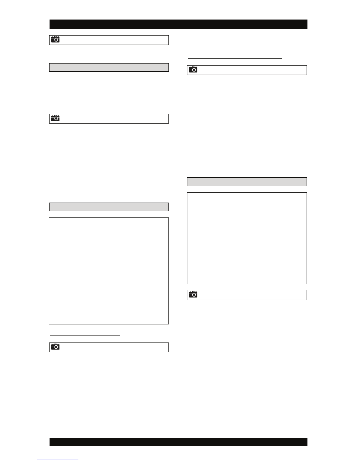
Picture 1
To facilitate the installation, you may want to remove the
main cover from the water softener (Ultra Mini only).
BLUE CAP OF COVER
To reduce the shipping dimensions, the blue cap of the
cover is NOT installed onto the water softener, but
delivered separately with 2 stainless steel mounting
screws. It needs to be assembled upon installation of the
water softener.
Picture 2
1. Remove the 2 stainless steel mounting screws from
the blue cap.
2. Open the cover in order to have access the inside of
the cover:
•Ultra Mini: pull the cover upwards and/or forwards
and remove it from the brine cabinet.
•Ultra Maxi: flip the cover up.
3. At the outside of the cover, put the blue cap in the
correct position and fix it to the cover by screwing the
2 stainless steel mounting screws into the
corresponding brass threaded inserts in the bottom of
the blue cap.
INLET & OUTLET
þCheck the water pressure at the place of installation
of the water softener; it should never exceed 8,3 bar.
þIn case of high concentration of impurities in the inlet
water, we recommend the installation of a sediment
filter, ahead of the water softener.
þWe strongly recommend the use of flexible hoses to
connect the water softener to the water distribution
system; use hoses with a large diameter in order to limit
the pressure loss.
þIf the water softener is not equipped with the factory
bypass (optional), we strongly recommend to install a 3-
valve bypass system (not included with this product!) to
isolate the water softener from the water distribution
system in case of repairs. It allows to turn off the water to
the water softener, while maintaining (untreated) water
supply to the user.
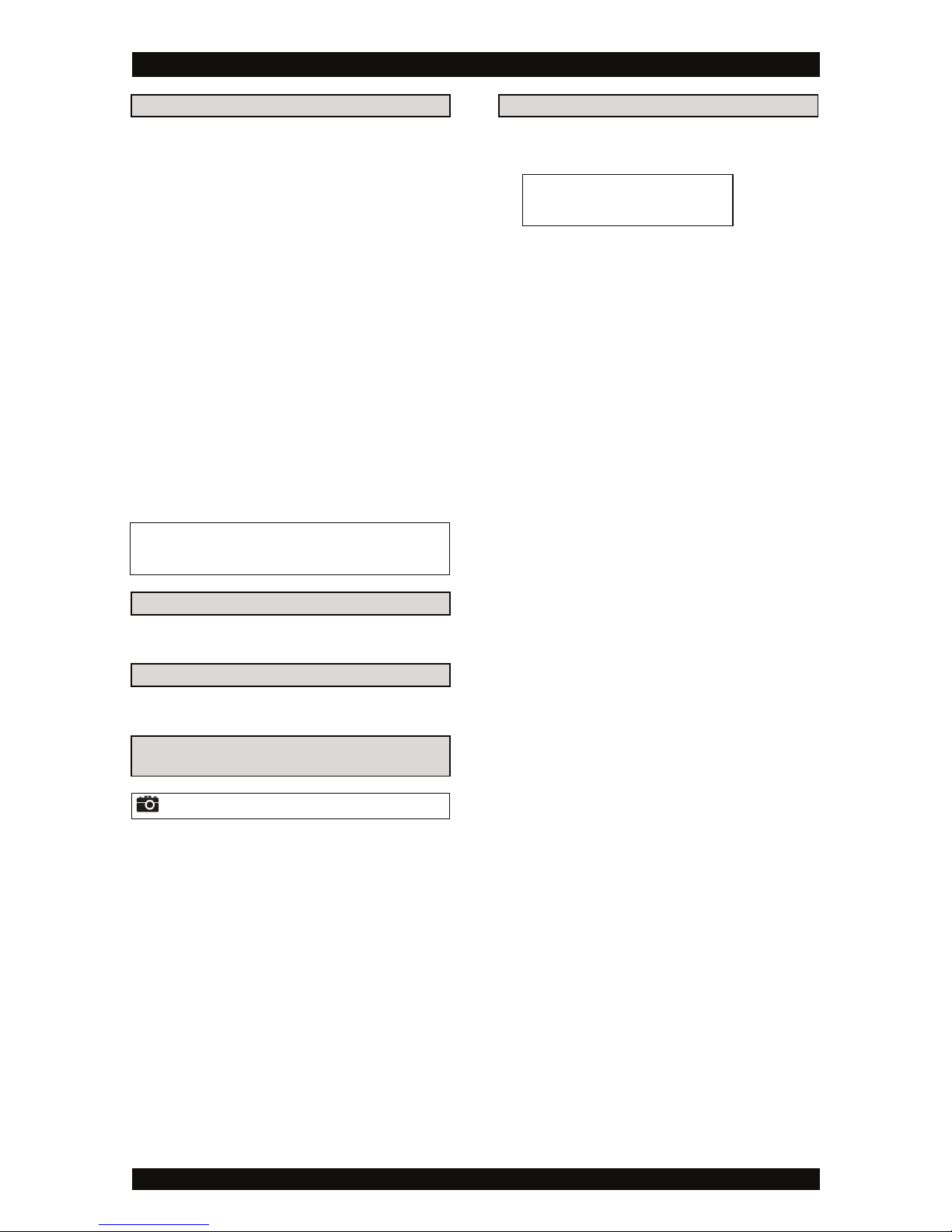
WITH FACTORY BYPASS (optional)
Picture 3
u= mains water supply (untreated water)
v= inlet of water softener (untreated water)
w= outlet of water softener (treated water)
x= house/application (treated water)
1. Screw the factory bypass onto the elbow connections
of the water softener (v&w); make sure to install the
gasket seals. Tighten the nuts firmly by hand.
2. Screw the connection kit with nuts onto the factory
bypass (u&x); make sure to install the gasket seals.
Tighten the nuts firmly by hand.
3. Connect the mains water supply to the nipple on the
inlet port of the factory bypass (u).
4. Connect the house/application to the nipple on the
outlet port of the factory bypass (x).
WITH 3-VALVE BYPASS SYSTEM (not included)
Picture 4
u= mains water supply (untreated water)
v= inlet of water softener (untreated water)
w= outlet of water softener (treated water)
x= house/application (treated water)
1. Install the 3-valve bypass system.
2. Screw the connection kit with nuts onto the elbow
connections of the water softener (v&w); make sure
to install the gasket seals. Tighten the nuts firmly by
hand.
3. Connect the 3-valve bypass system to the nipples on
the in (v) and out (w) elbow connections.
4. Connect the mains water supply to the inlet of the 3-
valve bypass system (u).
5. Connect the house/application to the outlet of the 3-
valve bypass system (x).
DRAIN
þWe recommend the use of a stand pipe with air trap.
þTo prevent backflow from the sewerage system into
the water softener, always make sure to have an air gap
between the end of the drain hose and the sewerage
system itself; as a rule of thumb, the air gap should be
minimum 2x the diameter of the drain hose.
þAlways use separate drain hoses for the control valve
(evacuation of rinse water) and the softener cabinet's
overflow.
þLay-out the drain hoses in such a way that pressure
loss is minimized; avoid kinks and unnecessary elevations.
þMake sure that the sewerage system is suitable for
the rinse water flow rate of the water softener.
Picture 5
1. Connect a 13 mm hose to:
•Ultra Mini: the drain solenoid of the control valve
(u); secure it by means of a clamp.
•Ultra Maxi: the adaptor on the drain line extender
of the control valve (u); secure it by means of a
clamp.
2. Run the drain hose to the sewerage system and
connect it to the stand pipe assuring sufficient air gap.
This drain line operates under pressure, so it may be
installed higher than the water softener.
3. Connect a 13 mm hose to the cabinet overflow elbow,
located at the back side of the water softener; secure
it by means of a clamp.
4. Run the drain hose to the sewerage system and
connect it to the stand pipe assuring sufficient air gap.
This drain line does NOT operate under pressure, so it
may NOT be installed higher than the water softener.