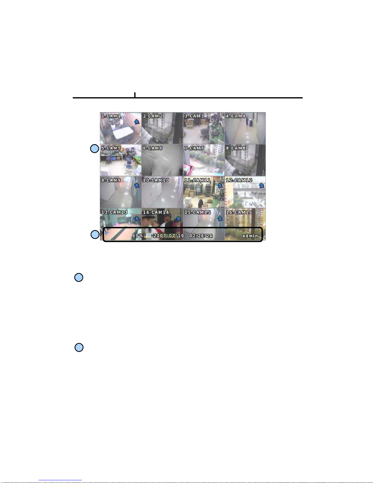
UltraCCTV TIGON 1648 User manual

1
User’s Manual
ULTRA CCTV
TIGON 1648
Digital Video Recorder
Open the CD DISC for
1. Complete user and installation manual.
2. Central Management Software.
3. Remote Viewing AP Software.

2
0 ~ 9: Channel select
Zoom: Live zoom (2x)
FREEZE: Freezing live image
Power: Power On / Off switch
REC: Recording
PLAY: Playback
SEQ.: Channel sequence
Split screen selection
MENU: Shortcut of frequently use functions
Setup: Enter setup OSD menu
Spot: Activate Call monitor. Quick Setup (Sequence ON/OFF, Fixed camera)
Frame by frame
reverse Frame by frame
forward Fast reverse Fast forward
Stop playback
Direction button up/down/left/right
Enter button
PTZ: Enter to PTZ control mode
ESC: Exit menu
Alarm : Alarm output force control
Backup: Enter to backup mode

3
2) LOOP OUT Connection
3) Monitor Connection
It connects audio source (mic) to audio
input of RCA and connects speaker to
audio output.
It supports 10/100 BaseT, connects
Cat5 cable with RJ-45
System rear connection detail
1) Video Source Connection
It connects video sources (camera image) to BNC connector via cable.
BNC connector of LOOP OUT can be used as output to other device’s input.
Caution : It may cause low quality of picture when connecting disconnected cable from any device
to LOOP OUT BNC.
CVBS OUT/SPOT : It connects normal CCTV CRT monitor.
S-VHS : It connects monitor that supports S-VHS(S-VIDEO)
VGA : It connects PC monitor or LCD monitor (not supporting DVI)
4) Audio Connection 5) Network Connection

4
6) RS232 port Connection.
Reserve for technical support
Both USB port support USB devices such as USB mouse, USB external HDD and USB thumb
drive
* Alarm output 1~4CH
Support either NC or NO
Remark: Max24V/2A
7) USB port Connection
8) ALARM IN (SENSOR) Connection
Remark : Max 6V/50mA
9) ALARM OUT Connection
front rear

5
Press the factory reset switch located at the left side of NTSC/PAL switch to return to factory
default setup values.
This reset switch should be pressed during power on. After OSD prompts "Factory reset
detected" message, then you can release the switch. The booting procedure would go on under
resetting setup values
Turn off the DVR before you do the NTSC/PAL system change.
Restart the DVR again after the system mode changed is done.
North America: NTSC
Europe: PAL
10) Factory Reset Switch and NTSC/PAL system Switch
Factory Reset Switch
NTSC/PAL Shift Switch
11) Power Connection and power switcher

6
Installation Guide for HDD & CD-RW/DVR-RW devices
You must set the hard drive Master and Slave jumper properly according to Hard drive
manufacturer's instructions to prevent system error and data loss.
Description
JR 1 : PRIMARY
JR 2 : SECONDARY
1. CD-RW/DVD-RW devices should be installed as “Primary Slave”.
2. First HDD for system needs to be installed as “Primary Master”.
Guide Chart for installing several HDDs
MASTER : HDD#1
SLAVE : CD/DVD
MASTER : HDD#2
SLAVE : HDD#3
JR 2
SECONDARY
SLAVE
HDD#3
JR 2
SECONDARY
MASTER
HDD#2
SYSTEMJR 1
PRIMARY
MASTER
HDD#1
HDD x 3
JR 2
SECONDARY
MASTER
HDD#2
SYSTEMJR 1
PRIMARY
MASTER
HDD#1
HDD x 2
JR 1
PRIMARY
SLAVE
SYSTEMJR 1
PRIMARY
MASTER
HDD#1HDD x 1
ConnectorIDEConnectorIDE
CD-RW/ DVD-RW
Devices
System
HDD
HDDInstalled

7
System On
• Put the power to the DVR.
• Turn on the power switch at the rear and press power button in front.
• It takes about 100 seconds to boot (It may take more when network cable isn’t connected)
System Shutdown
• Press Power button, then shutdown menu appears. Enter power button to shutdown system.
• Or select [SETUP > SYSTEM > SYSTEM SHUTDOWN] to shutdown system.
•It takes 30 seconds to shutdown.

8
OSD :
<Screen Indication>
Top-Left : Camera title
P – Pan/tilt (PTZ control)
A – Audio
Top-Right : Record mode (Blue-Normal, Red-Event)
Motion status
Central : Video Loss, Hidden Camera
Status Bar : DVR status Indication
(Backup, HDD usage, Current Time, SEQUENCE, FREEZE, Login info. etc)
1
2
1
2
on Screen

9
Screen Split
Press DISPLAY button or mouse menu: changed on 1 -> 4 -> 9 -> 16 by turn
Direct Channel
1) Press channel No. on the remote control or front panel.
2) Click the screen to watch specific channel using mouse.
** Pressing No.1 button responds a bit delayed to wait a possible signal input of
No.10~16 (approx 2.5 seconds)
It is recommended to change ID and PW for your safety.
LOG IN
Login to menu for setup
Default: ID – admin
PASSWORD - 1
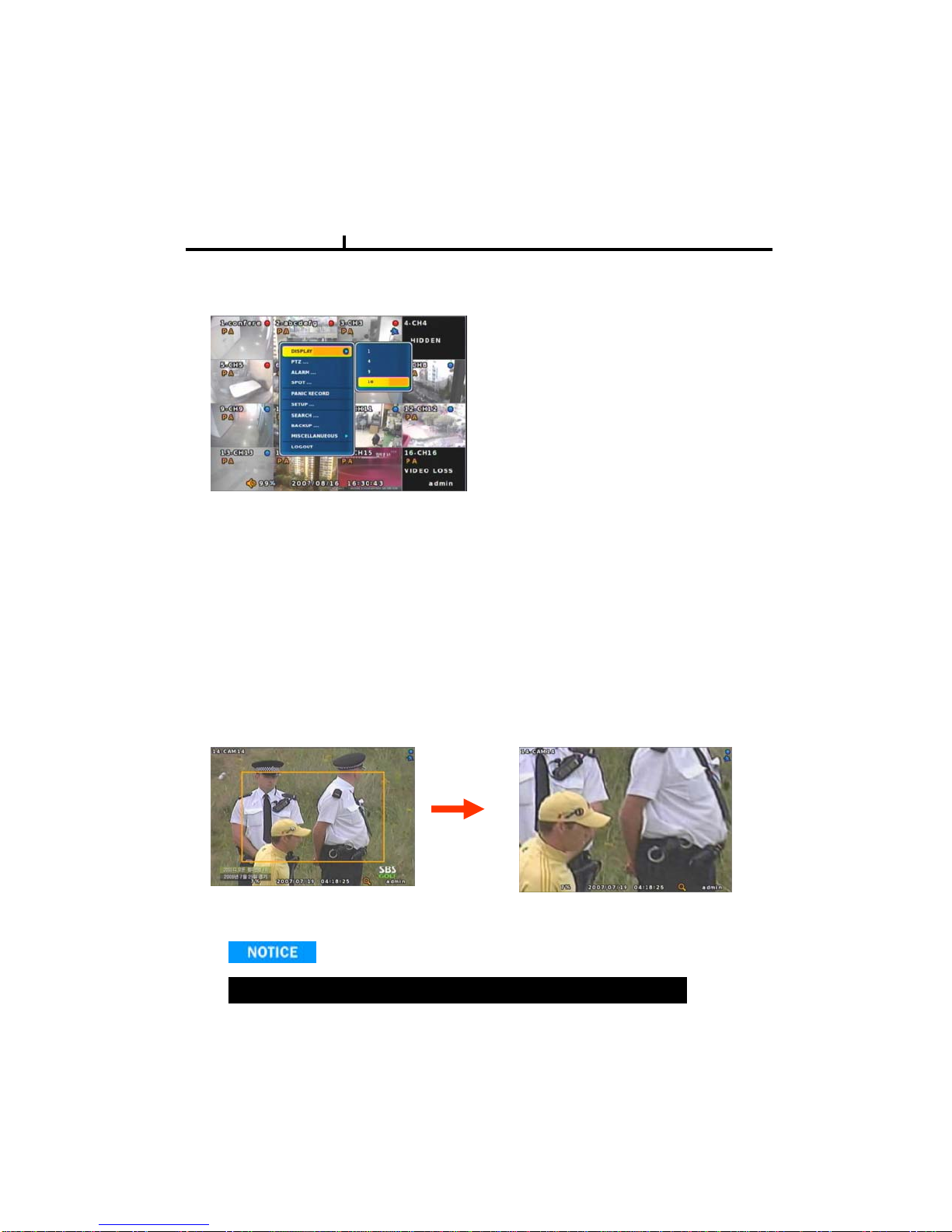
CAMERA ALLOCATION function (changing camera display position)
Ex) Switching camera No 4 and 12.
12
1) Press Enter in the monitoring screen, then
box is selected at No.1 camera.
2) Locate the box to the camera No. you want to
move using direction buttons.
3) Enter the camera number to switch
4) Then, selected camera is switched with the
Camera number you pressed.
5) To exit, press ESC

10
Menu Bar * Click MENU button or right button of mouse
DISPLAY
1, 4, 9, 16
: Split screen change (the same as DISPLAY button)
Also can split 4 division window for display
ch1 ~ ch4 , ch5 ~ ch8 , ch9~ ch12 , ch13 ~ ch16
ZOOM
1 Full Live screen available only.
Select Zoom : Press zoom button and locate the box to magnify using direction keys
Move Zoom : It can be moved using direction key after press Enter.
Zoom screen may provide low quality or be shaken as formatted digitally.
<ZOOM selected screen> <ZOOM screen>
SEQUENCE
Sequence camera group regularly
FREEZE
Pause the screen
MISCELLANUEOUS

11
PTZ
Pan Tilt/Zoom/Focus/Iris Preset setting and moving functions are supported.
Each function can be different from each PTZ protocol.
ALARM
Control Alarm output function.
SPOT
2 spot monitors are supported and sequence / fix mode can be selected.
Select the Spot monitor in SETUP>DEVICE>SPOT MONITOR.
No OSD indication of camera number for SPOT output.

12
STATUS
RECORD
Displays current recording status
EVENT
Displays current event information (motion/alarm).
DISK
Displays current Disk information
NETWORK
Displays current network information.
Also displays current connected client information.

13
PANIC RECORD
Set recording mode in an emergency situation.
Press SETUP>RECORD> EVENT RECORD>FPS/QUALITY
SETUP
Select to enter into SETUP menu
CAMERA COLOR
Changes camera screen color
OSD
Changes OSD (On Screen Display's position.
SEARCH
Select to enter into SEARCH menu

14
BACKUP
Select to backup recorded data.
1) Backup Device Search
2) Select data to backup
3) Calculate data size
4) Warning when data size is over
5) Make Image after pressing OK.
6) Burning to CD
It would block remote search during local backup procedure.
If users use defective media to backup, it might cause system reset

15
BACKUP
Use USB device to backup .
1) Backup Device Search
2) Select USB device to backup
3) Calculate data size
4) Warning when data size is over
5) Copy data to USB driver
6) Backup to USB completed

16
MUTE
Sound off
LOGOUT
Press SETUP>SYSTEM>USER
Note : After Backup to USB device , use windows Media Player to play the AVI file , if
your Media Player can’t shows any video , it should be the codec problem , you have
to visit the Xvix web site , http://www.xvid.org to download the Xvid codec and install
to your computer .
1) Media Player can’t shows any video 2) Visit the Xvid web site to download Xvid codec
http://www.xvid.org

17
SYSTEM SETUP
INFORMATION: To show DVR information
DATE/TIME : Setup date and time
DISK : Show the HDD status and format HDD
USER : User login ID and password setup
LOG : System operation information
LOGOUT : Logout system
SYSTEM SHUTDOWN: To shut down DVR
Remark: It takes more than 10 seconds to initialize (delete) the LOG information
SETUP SCREEN

18
INFORMATION
DEVICE NAME: User can change the DVR
name on his own.
LANGUAGE : Select language.
VERSION : Shows S/W version info.
(With UPGRADE button, you can upgrade
the newest S/W version)
INFORMATION
Contact manufacturer or distributors for more
Upgraded version .
CONFIGURATION IMPORT : You can read setup values saved in USB or
Initialize the setup values
CONFIGURATION EXPORT : You can record setup values in USB equipment.

19
DATE/TIME
DATE/TIME
Set date, time & Time zone of System.
When you use it for the first time
Set these items in advance .
It takes more than 50 seconds to
validate time setting.
TIME SYN
Synchronize time with internet time server.
Default time zone is USA CST
Set the GMT on the DATE/TIME list and
Adjust TIME SYNC.
HOLIDAY
In the schedule record setup , it automatically
converts normal date to holiday schedule.
It works when record is setup as schedule mode.
It takes 90 seconds to validate holiday list
NTP server function is only for DVR client

20
DISK
DISK TABLE
Shows current disk information connected to
system.
IMPORTED : DISK installed
RECORD : RECORD possible
SYSTEM : DISK allotted for SYSTEM
TOTAL DISK FORMAT
Format all connected HDD disks.
(When you select info column of connected DISK separately,
You can format DISK one by one.
It takes more than 200 seconds to format a 750 GB hard disk
One of DISKS should be a system disk for recording system logs & other TEMP file issuing
purposes.
<SYSTEM DISK selected Screen> <On FORMAT Screen>
Backup devices such as CD-RW/DVD-RW need to be installed as Secondary Slave.
(JR 2 Connector. – Slave jumper setting)
Table of contents
Popular DVR manuals by other brands

American Dynamics
American Dynamics Intellex Intellex DVMS Installation and configuration guide

Stortech
Stortech MDVR 800 series quick start guide

GeoVision
GeoVision GV-Hot Swap DVR System installation guide

Zartek
Zartek ZA-180 user manual

Jazz
Jazz HDV146 instruction manual

Swann
Swann M88200H210313E user manual