2
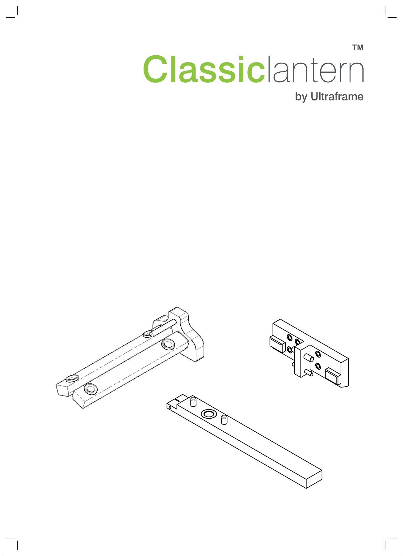
Spigot Nut
PSUB
Glazing Support Trim
1
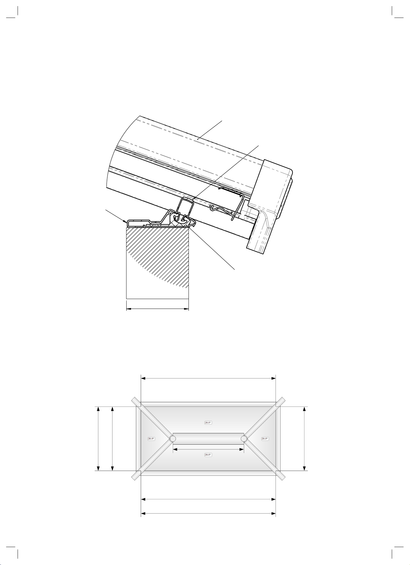
Cutting the Rider Rail & Sleeve
Tip: Slide the rider rail inside the uPVC sleeve. This will make it quicker to cut and mitre
each section and will give greater accuracy.
Working from the roof plan supplied in the Classic software fabrication report, mitre the
rider rail and sleeve to the dimensions specified for the sleeve on the cutting list.
Note: The dimension given in the report relates to the overall (external) length of the
section including any mitres that may be added.
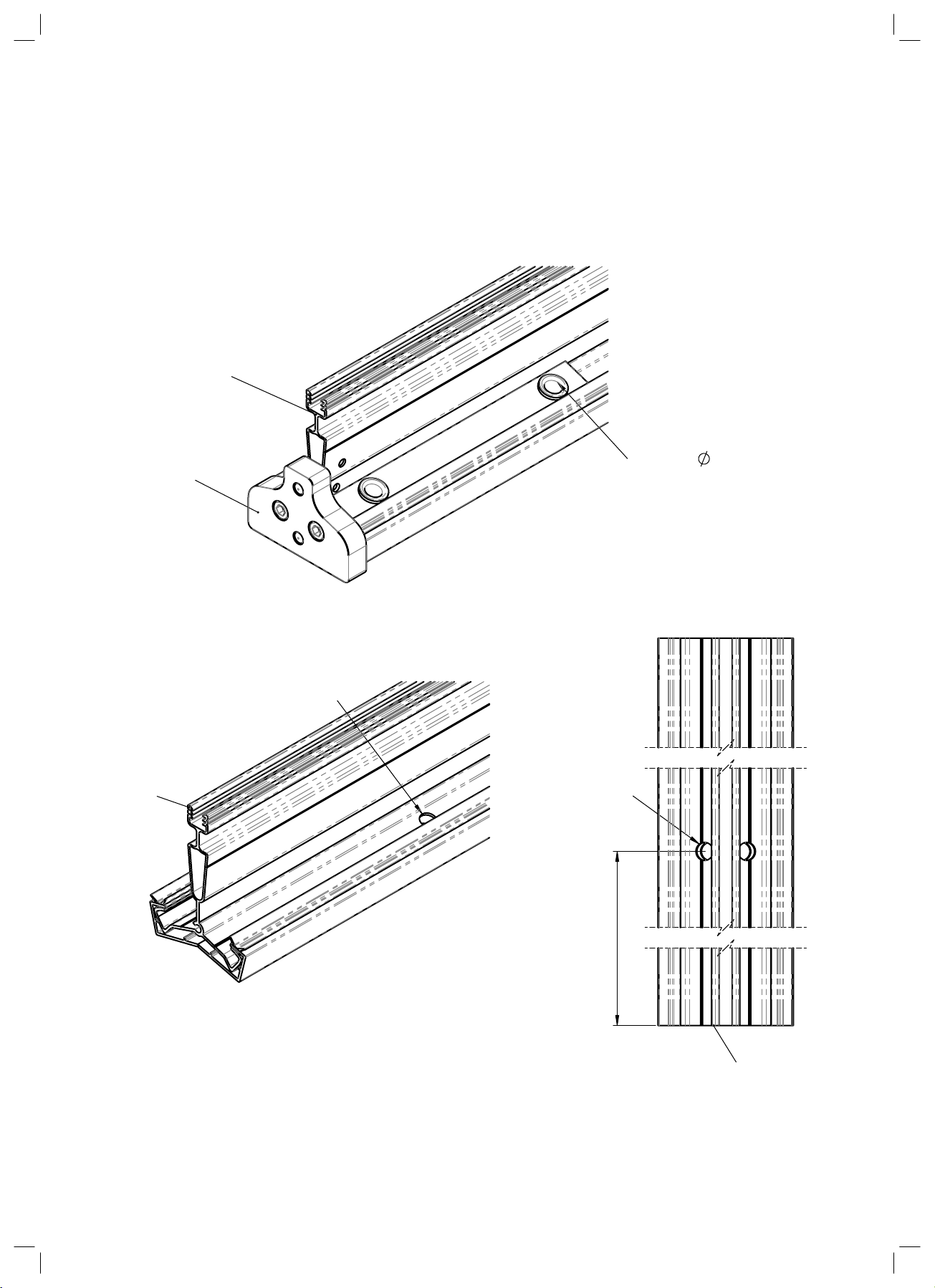
Cutting the Rider Rail & Sleeve
1. Once all four rider rail sleeve sections have been mitred, cut the glazing support
sections to the lengths and angles specified in the PVC cutting list. If you wish to square
cut sections 27mm should be deducted from the overall length.
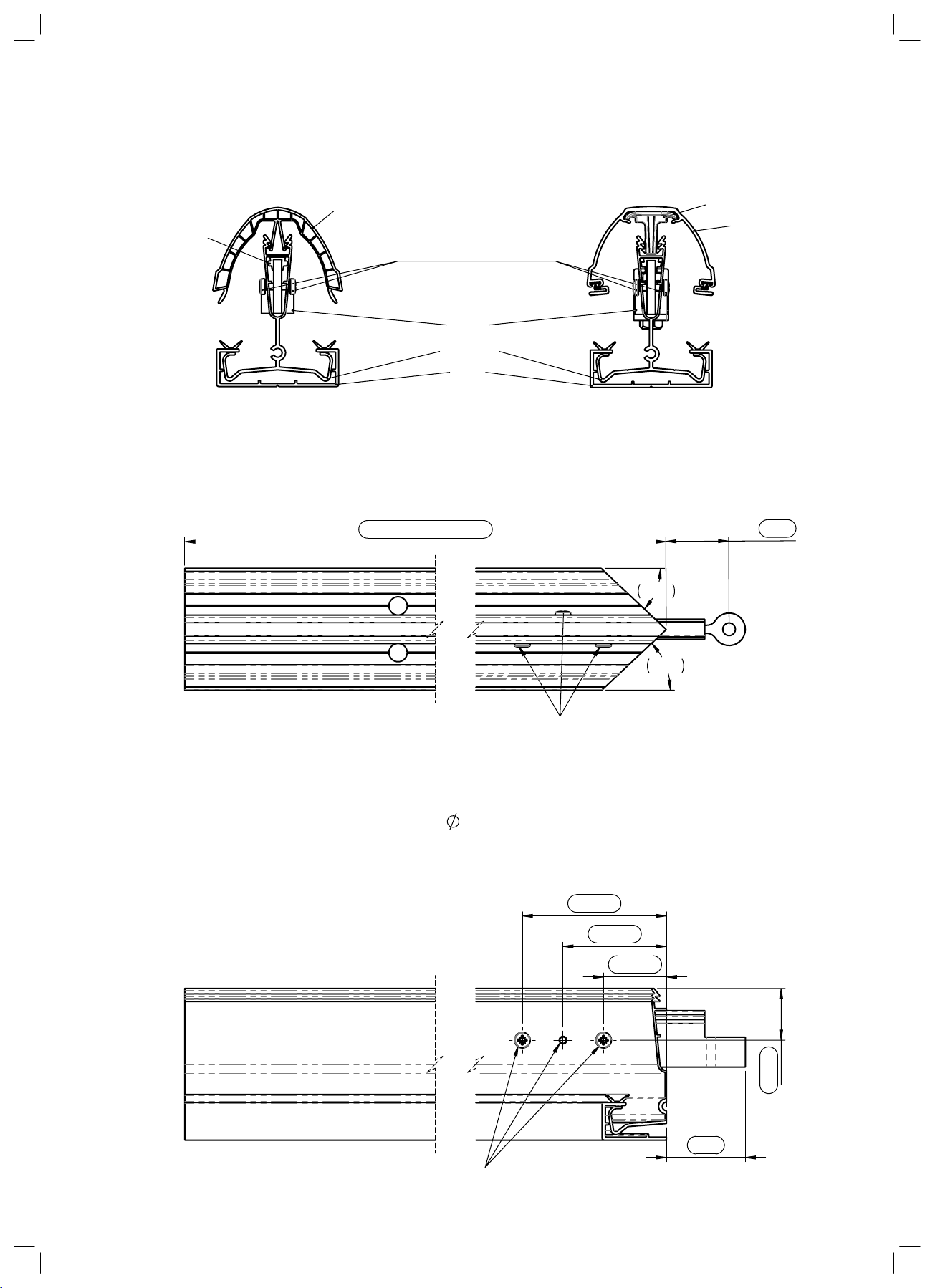
2. Once all glazing support sections have been cut, insert the sections into the rider rail
bolt slot in the orientation shown below. If there are any bars other than the hips, ensure
that the bolts have been inserted into the bolt slot prior to inserting the glazing support
sections.
3. Finally insert any bolt for the hip bars at the ends of the rail. Secure these with a spiggot
nut to stop them from coming loose in transit.
5