ULTRAFRYER F-E21-14 User manual

FOR YOUR SAFETY
Do not store or use gasoline or other flammable vapors or liq-
uids in the vicinity of this or other appliance.
WARNING
Improper Installation, adjustment, alteration, service, or main-
tenance can cause property damage, injury, or death. Read the
installation, operating, and maintenance instructions thor-
oughly before installing or servicing this equipment.
PN 30A255 June 2014 Rev A 1
302 Spencer Lane • P.O. Box 5369 San Antonio, Texas 78201
(800) 525-8130 • (210) 731-5000 • Fax: (210) 731-5099
www.ultrafryer.com
Ultrafryer Electric Fryer
Model F-E21-14
Operation Instructions

PREFACE
This Manual was written and published by the Engineering Department, Ultrafryer Systems for use by personnel
who will operate a Model FM-E-21 Electric Fryer in a commercial cooking environment.
This appliance is intended for professional use and is to be operated by qualified personnel.
Throughout this manual, NOTES, CAUTIONS, and WARNINGS are used to alert the operator to items of special
circumstances. These items are identified as follows:
NOTE:
CAUTION: To assure producing a quality product while prolonging the life expectancy of the fryer,
ensure that the boil-out, and cleaning instructions are strictly followed.
WARNING: Do not allow any cleaning solution or water to splash into a vessel of hot cooking
oil, as it will contaminate the oil and may cause the oil to splatter, causing severe burns.
This manual is intended as a guide for all Basic Model Fryers, regardless of configuration and controllers. It is to be used in
conjunction with the applicable controller manual that is included with the fryer.
2
PN 30A255 June 2014 Rev A

TABLE OF CONTENTS
GENERAL INFORMATION
Warranty . . . . . . . . . . . . . . . . . . . . . . . . . . . . . . . . . . . . . . . . . . . . . . . . . . . . . . . . . . . . . . . . . . . . . . . .5
Safety . . . . . . . . . . . . . . . . . . . . . . . . . . . . . . . . . . . . . . . . . . . . . . . . . . . . . . . . . . . . . . . . . . . . . ….. . . 6
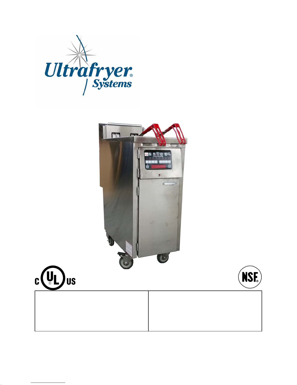
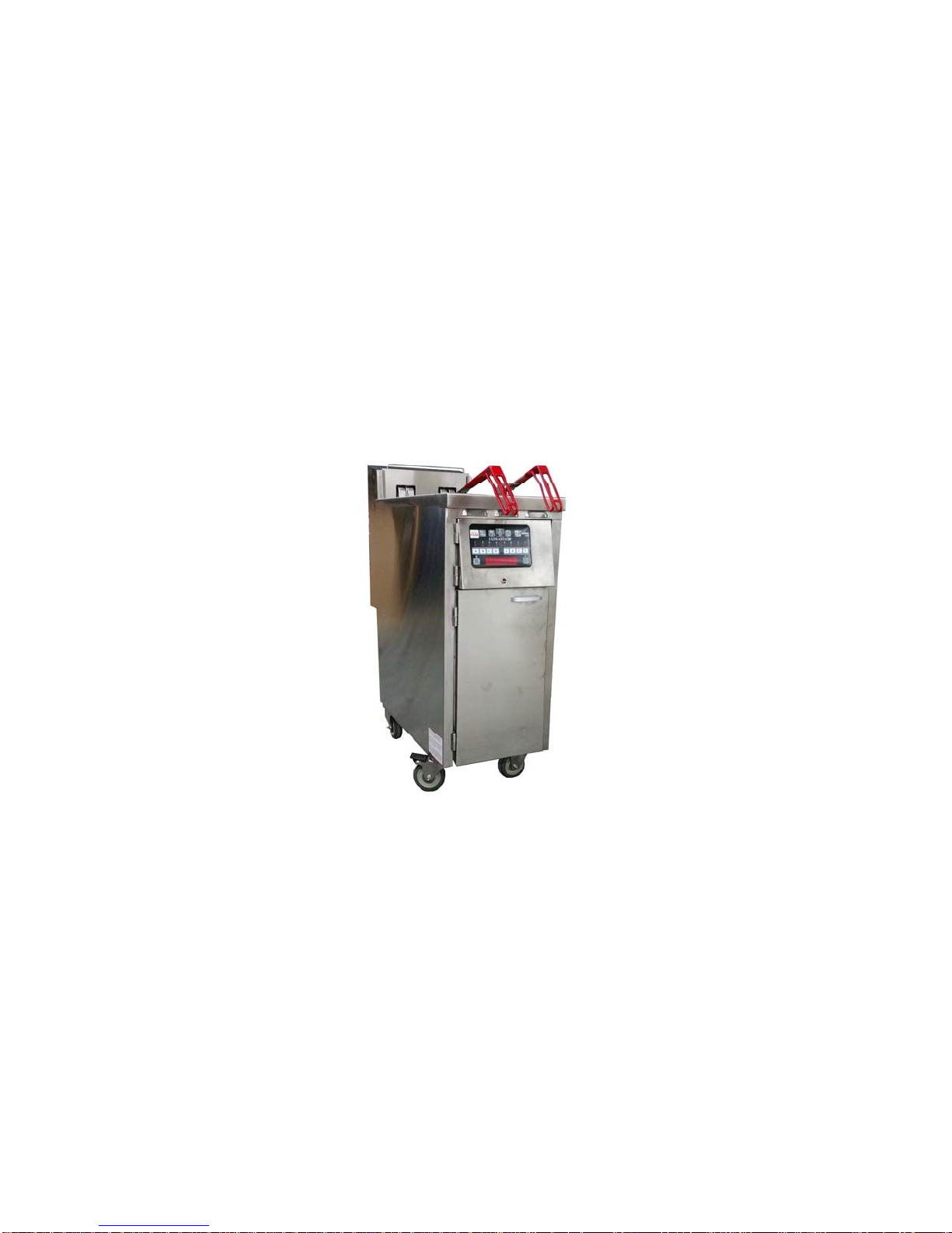
Description/ Specifications. . . . . . . . . . . . . . . . . . . . . . . . . . . . . . . . . . . . . . . . . . . . . . . . . . . . . . . . 6
Dimensions and Operational Requirements . . . . . . . . . . . . . . . . . . . . . . . . . . . . . . . . . . . . .. . . . . . .. .. 7
Operating Controls . . . . . . . . . . . . . . . . . . . . . . . . . . . . . . . . . . . . . . .. . . . . . . . . . . . . . . . . . . . . . ….. 7-8
Automatic Safety Features. . . . . . . . . . . . . . . . . . . . . . . . . . . . . . . . . . . . . . . . . . . . . . . . . . . . . …….. . 9
PRE-INSTALLATION
General . . . . . . . . . . . . . . . . . . . . . . . . . . . . . . . . . . . . . . .. . . . . . . . . . . . . . . . . . . . . . . . . . . . . . . . . . 11
Standards . . . . . . . . . . . . . . . . . . . . . . . . . . . . . . . . . . . . . . .. . . . . . . . . . . . . . . . . . . . . . . . . . . . . . . . .11
Air Supply and Ventilation . . . . . . . . . . . . . . . . . . . . . . . . . . . . . . . . . . . . . . .. . . . . . . . . . . . . . . . . .. . 11
RECEIVING AND INSTALLING
Unpacking . . . . . . . . . . . . . . . . . . . . . . . . . . . . . . . . . . . . . . .. . . . . . . . . . . . . . . . . . . . . . . . . . . . . . . .13
Installing . . . . . . . . . . . . . . . . . . . . . . . . . . . . . . . . . . . . . . .. . . . . . . . . . . . . . . . . . . . . . . . . . .. . . . . . .13
Leveling . . . . . . . . . . . . . . . . . . . . . . . . . . . . . . . . . . . . . . .. . . . . . . . . . . . . . . . . . . . . . . . . . . . . .. . . . 13
Electrical Connection . . . . . . . . . . . . . . . . . . . . . . . . . . . . . . . . . . . . . . .. . . . . . . . . . . . . . . . . . . . . . . .13
Ultrastat 25 Cooking Computer . . . . . . . . . . . . . . . . . . . . . . . . . . . . . . . . . . . . . . .. . . . . . . . . . . . . . . . 14
INITIAL START-UP
Initial Cleaning . . . . . . . . . . . . . . . . . . . . . . . . . . . . . . . . . . . . . . .. . . . . . . . . . . . . . . . . . . . . . . . . . . .16
Start-up. . . . . . . . . . . . . . . . . . . . . . . . . . . . . . . . . . . . . . .. . . . . . . . . . . . . . . . . . . . . . . . . . . . . . . . . ..16
Initial Fryer Boil-out . . . . . . . . . . . . . . . . . . . . . . . . . . . . . . . . . . . . . . .. . . . . . . . . . . . . . . . . . . . . . . .16
PREVENTIVE MAINTENANCE AND TROUBLESHOOTING
Preventive Maintenance. . . . . . . . . . . . . . . . . . . . . . . . . . . . . . . . . . . . . . .. . . . . . . . . . . . . . . . . . . . . .18
Troubleshooting . . . . . . . . . . . . . . . . . . . . . . . . . . . . . . . . . . . . . . .. . . . . . . . . . . . . . . . . . . . . . . . . . . 19
Troubleshooting Chart . . . . . . . . . . . . . . . . . . . . . . . . . . . . . . . . .. . . . . . . . . . . . . . . . . . . . . . . . . . . . 19
Cleaning
General . . . . . . . . . . . . . . . . . . . . . . . . . . . . . . . . . . . . . . .. . . . . . . . . . . . . . . . . . . . . . . . . . . . . . . . . . .21
Daily . . . . . . . . . . . . . . . . . . . . . . . . . . . . . . . . . . . . . .. . . . . . . . . . . . . . . . . . . . . . . . . . . . . . . . . . . . . .21
Weekly. . . . . . . . . . . . . . . . . . . . . . . . . . . . . . . . . . . . . . .. . . . . . . . . . . . . . . . . . . . . . . . . . . . . . . . . . . .21
FRYER OPERATION
General . . . . . . . . . . . . . . . . . . . . . . . . . . . . . . . . . . . . . . . . . . . . . . . . . . . . . . . . . . . . . . . . . . . . . . . . . .23-24
Ultrastat 25 Cooking Computer . . . . . . . . . . . . . . . . . . . . . . . . . . . . . . . . . . . . . . . . . . . . . . . . . . . . . . .25
Shortening Installation . . . . . . . . . . . . . . . . . . . . . . . . . . . . . . . . . . . . . . . . . . . . . . . . . . . . . . . . . . . . . .25
Start-Up and Cooking . . . . . . . . . . . . . . . . . . . . . . . . . . . . . . . . . . . . . . . . . . . . . . . . . . . . . . . . . . . . . . .25
Shortening Disposal . . . . . . . . . . . . . . . . . . . . . . . . . . . . . . . . . . . . . . . . . . . . . . . . . . . . . . . . . . . . . . . . 25
Fryer Boil-out . . . . . . . . . . . . . . . . . . . . . . . . . . . . . . . . . . . . . . . . . . . . . . . . . . . . . . . . . . . . . . . . . . . . .26
Fryer Shut Down Procedure . . . . . . . . . . . . . . . . . . . . . . . . . . . . . . . . . . . . . . . . . . . . . . . . . . . . . . . . . .26
TECHNICAL ASSISTANCE & ORDERING INFORMATION
Technical Assistance . . . . . . . . . . . . . . . . . . . . . . . . . . . . . . . . . . . . . . . . . . . . . . . . . . . . . . . . . . . . . . . 28
Ordering Information . . . . . . . . . . . . . . . . . . . . . . . . . . . . . . . . . . . . . . . . . . . . . . . . . . . . . . . . . . . . . . .28
RECOMMENDED SPARE PARTS. . . . . . . . . . . . . . . . . . . . . . . . . . . . . . . . . . . . . . . . . . . . . . . . .. .30
PARTS IDENTIFICATON
Parts Identification . . . . . . . . . . . . . . . . . . . . . . . . . . . . . . . . . . . . . . . . . . . . . . . . . . . . . . . . . . . . . . . . 32-33
WIRING DIAGRAM
Wiring Diagram . . . . . . . . . . . . . . . . . . . . . . . . . . . . . . . . . . . . . . . . . . . . . . . . . . . . . . . . . . . . . . . . . .. 35
ACCEPTABLE ALTERNATE AND REQUIRED HI-LIMIT CONSTRUCTION
U.S. Fryer. Acceptable Alternate . . . . . . . . . . . . . . . . . . . . . . . . . . . . . . . . . . . . . . . . . . . . . . .. . . . . . . 37
Required for Canada Fryer Only. . . . . . . . . . . . . . . . . . . . . . . . . . . . . . . . . . . . . . . . . . . . . . . .. . . . . . . 37
PN 30A255 June 2014 Rev A 3

GENERAL INFORMATION
PN 30A255 June 2014 Rev A 4

PN 30A255 June 2014 Rev A 5

SAFTEY
The major safety concern associated with the Ultrafryer Electric Fryer is burns from hot shortening. In order to prevent serious
burns, good housekeeping habits are required. The floor in front of and the area around the fryer should be kept clean and dry.
Whenever anything is placed into a fryer vat, care should be used not to splash the hot shortening. Product should always be
“PLACED” into the shortening, not thrown. Safety goggles, neoprene insulated gloves, and an apron must be worn while boil-
ing-out a fryer vat. Electrical controls used in the electric fryer operate off of the 208 or 240 volts three phase electrical power,
and no adjustments or replacement of electrical controls or parts should ever be attempted without first disconnecting ALL
electrical power. FAILURE to do so can result in serious electrical shock or death. It should be determined that ALL electrical
power has been removed prior to beginning a repair The fryer and its controls should never be operated with wet hands or while
standing in water. To do so can result in serious electrical shock or death
Fire in liquid shortening should always be a constant concern of team members operating or working nearby the Electric Fryer.
The fryer should be equipped with a Fire Suppression system, that automatically OPENS the shunt trip circuit breakers,
removing electrical power from the fryer if a fire occurs. In addition, this system MUST be inspected by a licensed distributor
each six (6) months to assure it is operational.
DESCRIPTION / SPECIFICATIONS
ULTRAFRYER 14” (356 mm) ED14 ELECTRIC FRYER
The Ultrafryer 14" (356 mm) ED electric fryer was designed by Ultrafryer Systems® and is design-certified by the
Underwriters Laboratories (UL) and the National Sanitation Foundation (NSF). The fryer is shipped without the power cord
installed. The fryer is shipped assembled with the accessories packed inside the fryer vat, and each fryer has been adjusted,
tested and inspected prior to shipment. This electric fryer is designed to be used in a commercial food preparation environment
after it is properly installed as outlined
in this manual.
6
PN 30A255 June 2014 Rev A

SPECIFICATIONS
MODEL 14” (356 mm) ED14 ELECTRIC FRYER
OPERATIONAL REQUIREMENTS
NOTE:
Test Start-Up, Operation. Cooking, Filtering and Boil Out Procedures of a 14” Model ED Electric Fryer in the manual
are based on the Ultrastat 25 Cooking Computer. Refer to Manual P/N 30A051 to perform these functions in a fryer
equipped with this controller.
OPERATING CONTROLS
The fryer is equipped with an Ultrastat 25 Cooking Computer as shown below. Operating instructions for the Ultrastat 25
Cooking Computer (P/N 30A051) will be provided with the fryer. Operating controls on the fryer include the Ultrastat 25
Cooking Computer and the Red Heating Indicator Lamp, these controls are mounted on the Controller Door;. The Temperature
P robe and Hi-Limit Switch, these controls are located inside the vat. The Drain Ball Valve, On/Off Power Switch and Red
Hi-Limit Indicator Lamp, these controls are located behind the Service Access Door. These controls were identified in the illus-
trations shown on the next page.
7
PN 30A255 June 2014 Rev A
SPECIFICATION ITEM 14” ED
Overall Width 14.836” (377mm)
Overall Depth 31.686” (807mm)
Work Height 36” (914mm)
Oil Capacity
High Level
Low Level
63 lbs (28.6 liters)
37 lbs (16.8 liters)
Vat Container Size 13.918” x 17.375” (354mm x 441mm)
Shipping Cube 23” x 42” x 54” (59mm x 107mm x 138mm)
Shipping Weight 175 lbs (79.4 kgs)
Electrical Requirement 208 / 240 Volt
3 Phase
21 KW / Vat

Operating Control Locations
MODEL 14” (356 mm) ED14 ELECTRIC FRYER
8
PN 30A255 June 2014 Rev A
Temperature
Probe
Hi-Limit
Switch
Ultrastat 25
Cooking Computer
Power
On/Off Switch
Red Hi-Limit
Indicator Lamp
Electrical
Box Assy
Red Heating
Indicator Lamp

AUTOMATIC SAFETY FEATURES
1. Hi-Limit Thermostat Switch with Auto Reset
2. Red Hi-Limit Indicator Lamp to indicate hi-limit has been exceeded
3. Ultrastat 25 Controller will power off when hi-limit has been exceeded
9
PN 30A255 June 2014 Rev A

PRE-INSTALLATION
PN 30A255 June 2014 Rev A 10

A. GENERAL: Safe and satisfactory operation of a Model F-E21-14 Electric Fryer depends on its proper installation.
Installation must conform to local codes or, in the absence of local codes, with the current National Electrical Code
ANSI NFPA 70 (latest edition). In Canada, electrical installation shall be in accordance with the current Canadian Electrical
Code CSA C22.1 and/or local codes. Each Model F-E21-14 fryer should be installed as follows:
1. Power cord should be installed on the fryer electrical box assy
2. Placed beneath a properly designed exhaust hood
3. Installed by a licensed electrician.
4. Connected to the voltage type for which the unit was fabricated as indicated on the fryer.
5. Restrained by use of a restraining device to avoid splashing of hot liquid and to assure tension cannot be placed on the
flexible power cable or connectors. CLEARANCES: The appliance must be kept free and clear of all combustibles. The
minimum clearance from combustible and non-combustible construction is 6" (152 mm) from the sides, and 6" (152 mm)
from rear. The fryer may be installed on combustible floors.
NOTE: Adequate clearances must be provided for servicing and proper operation.
B. STANDARDS: Installation must be planned in accordance with all applicable state and local codes, taking into account the
following standards:
1. When installed the fryer must be electrically grounded in accordance with local codes, or in the absence of local codes, in
accordance with the current National Electrical code ANSI/NFPA 70 (latest edition). In Canada electrical installation must
be in accordance with the current Canadian Electrical Code CSA C22.1 and CSA 22.1 as applicable and/or local codes.
2. Other applicable nationally recognized installation standards such as:
a. NFPA Standards #54, #94 and #221 (latest edition)
National Fire Protection Association
470 Atlantic Avenue
Boston, MA 02110
b. ANSI Z21.69/CAN/CGA-6.16 AND Z21.41/CAN1 6.9
5. Exhaust vent hood, when installed must conform to the current NFPA 54-1 and Canadian CAN/CGA-1.11 (latest edition)
NOTE: Local building codes will usually not permit a fryer with its open tank of hot oil to be installed immediately next to an
open flame of any type, whether a broiler or an open burner or range. Check local codes before beginning installation.
C. AIR SUPPLY AND VENTILATION: The area around the appliance must be kept clear of any combustible or flammable
products and avoid any obstruction to the flow of ventilation air as well as for ease of maintenance and service. NOTHING
is to be stored in the interior of the fryer’s cabinet.
1. A means must be provided for any commercial, heavy duty-cooking appliance to exhaust combustion wastes outside of
the building. It is essential that a fryer be set under a powered exhaust vent hood or that an exhaust fan be provided in the
wall above the unit
2. The open tank of hot oil, makes the storage of anything on shelving over or behind the fryer unsafe.
3. Filters and drip troughs should be part of any industrial hood, but consult local codes before constructing and installing
any hood.
4. Provisions must be made for an adequate supply of fresh air and adequate clearance must be maintained for air openings
PN 30A255 June 2014 Rev A 11

RECEIVING AND INSTALLING
PN 30A255 June 2014 Rev A 12

PN 30A255 June 2014 Rev A 13
UNPACKING
Check that the container is upright. Use an outward prying motion – DO NOT USE A HAMMER - to remove the carton.
Check the fryer for visible damage; if such damage has occurred do not refuse shipment, but contact the carrier and file the
appropriate freight claims.
INSTALLING
Roll the assembled fryer into the building, to its operating location.
LEVELING
1. When the fryer is placed in its operating location check to be sure it is level. If not, loosen the casters and insert the appro-
priate number of shim plates between leg and caster plates then retighten the caster bolts.
2. If the floor is smooth and level, adjust to the high corner and measure with a spirit level. If the floor is uneven or has a
decided slope, level the unit with metal shims.
3. Leveling will assure that each vat contains the same amount of shortening when checked at the shortening level mark on
the rear wall of the fryer vat.
NOTE: A caster may not return exactly to the same position after being moved, which may require re-leveling after each move.
ELECTRICAL CONNECTION
Each Model F-E21-14 Electric Fryer is wired internally to operate on 208 or 240 volt 3 phase electrical power as shown on the
fryer. The 208 or 240 volt 3 phase circuit of the fryer is internally wired to the Fryer Electrical Box Assy which is to be used to
connect to the building power source. It is ESSENTIAL that the 208 or 240 volt electrical receptacle is located within 8 feet of
the fryer location and that provisions are made so that the fryer can be moved to service fryer from the rear. Electrical connec-
tions to the fryer should be made by a licensed electrician and they must conform to the NATIONAL ELECTRICAL CODE as
well as to local electrical codes and/or ordinances.
To avoid electrical hazards and assure proper operation of the electric fryer, the following precautions should be oserved
during installation:
MATCH VOLTAGE
Before connecting electrical power, insure the line voltage matches the voltage rating on the fryer.
CIRCUIT BREAKERS
The fryer must be connected to a circuit having shunt-trip circuit breakers sized in accordance with requirements of
the National Electrical Code as well as local codes and ordinances.
GROUNDING
The fryer MUST be grounded to the building ground system according to the National Electrical
Code and local codes/ordinances.
FIRE PROTECTION
The fryer should be installed beneath a powered exhaust hood which complies with NFPA96 standards
that is equipped with an approved Fire Suppression System designed to automatically shut-off all sources of electrical
power to the fryer in case of a vat fire.
CLEARANCES
The Model F-E21-14 Electric Fryer MUST be kept free and clear of all combustibles. The MINIMUM
clearances from combustible and non-combustible construction is 6" (152 mm) from the sides and 6" (152 mm) from
the rear of the fryer. The fryer may be installed on combustible floors.
WARNING: IMPROPER INSTALLATION, ADJUSTMENT, ALTERATION, SERVICE OR MAINTENANCE CAN
CAUSE PROPERTY DAMAGE, INJURY OR DEATH. READ THE INSTALLATION, OPERATING
AND MAINTENANCE INSTRUCTIONS THOROUGHLY BEFORE INSTALLING OR SERVICING
THIS EQUIPMENT.

PN 30A255 June 2014 Rev A 14
ULTRASTAT 25 COOKING COMPUTER
The Ultrastat 25 Cooking Computer is a high performance, micro-processor based electronic controller designed for use in
commercial appliance temperature and timing control applications. Utilizing a microcontroller board, membrane switch front
panel with a digital LED readout, and display board, the Ultrastat 25 Cooking Computer has been customized for Ultrafryer
Systems applications by the addition of up to (1O) stage cooking profiles for each of the (8) product keys, exit melt feature,
optional temperature setback and filtering promp, and can be programmed to cook products under "Flex" or "Straight" timing
modes. Operation of the Ultrastat 25 Cooking Computer is covered in the ULTRASTAT 25 Computer Operation
Instructions PN 30A051 provided with Fryers Equipped with that computer.

INITIAL START-UP
PN 30A255 June 2014 Rev A 15

PN 30A255 June 2014 Rev A 16
INITIAL CLEANING
New Electric Fryers are wiped clean with solvents at the factory to remove any visible signs of dirt, oil, grease, etc. remaining
from the manufacturing process, then given a light coat of oil. Each fryer should be THOROUGHLY washed with HOT
sanitizer solution to remove film residue, installation dust or debris and then wiped dry prior to placing the fryer into operation.
START-UP
The fryers are tested and adjusted prior to being shipped: however adjustments may be necessary on installation to meet local
conditions and to correct possible problems caused by rough handling or vibration during shipment. Initial adjustments are the
responsibility of the customer and will not be covered by the Ultrafryer Systems warranty.
NOTE: Adjustments must be performed by qualified personnel.
INITIAL FRYER BOIL-OUT
To test operate an Ultrafryer Electric Fryer equipped with an Ultrastat 25 Cooking Computer
1. Ensure the Fryer’s Power ON/OFF Switch is in the ON position
2. Ensure the Computer’s ON/OFF Button is in the OFF position
3. Ensure the Drain Ball Valve Lever is CLOSED
4. Fill the fryer vat with hot or cold water to the applicable shortening level mark on the rear of the vat
STEP ACTION RESPONSE
1 Ensure the Drain Ball Valve Lever is in the
closed position and the water is at the proper
level
CAUTION:
PRIOR TO PROCEEDING TO STEP 2, VISUALLY CHECK THAT THE HEATING
2 Turn the computer ON by pressing the computer
ON/OFF Button, then place the computer in the
BOIL MODE by press the TEMPERATURE Button
and the number 2, 1, 2 Buttons
BOIL 30:00 will appear in the computer display
The HEAT DEMAND LED on the computer and
the RED Heating Indicator Lamp on the fryer will
cycle ON and OFF to heat the water to 192 Deg F
(89 Deg C)
3 When the water begins to BOIL, press the computer
ON/OFF Button to exit the BOIL MODE The Computer Display will go BLANK
4 After the water in the vat and the metal surfaces of
the fryer have COOLED, drain the water into a floor
drain
CAUTION:
TURN OFF FRYER POWER BEFORE LIFTING HEATING ELEMENTS OUT OF WATER
OR SHORTENING

PREVENTIVE MAINTENANCE AND
TROUBLESHOOTING
PN 30A255 June 2014 Rev A 17

PREVENTIVE MAINTENANCE
Minimal maintenance is required on a 14" (356 mm) electric fryer because of its design and materials used in the manufacturing
process. However some preventive maintenance and inspection must be performed periodically to prevent breakdowns which
could curtail food sales. Any preventive maintenance or inspection should be accomplished with CAUTION while the fryer is
in operation since HOT liquid shortening could cause severe burns. If service or repair is required, all electrical power MUST
BE TURNED OFF PRIOR TO performing that service or repair.
PREVENTIVE MAINTENANCE SCHEDULE
DAILY
ITEM INSPECT FOR
Grease Filters Clean grease filters in the exhaust vet hood every evening and
allow them to dry overnight
WEEKLY
ITEM INSPECT FOR
Drain Valve Handle Determine the Drain Valve Handle is securely attached to the
drain valve and that the valve and be easily opened and closed
Temperature Sensing Probes During boil-out of the fryer, inspect the temperature and hi-limit
sensing probes for any visual damage
18
PN 30A255 June 2014 Rev A
CAUTION:
TURN OFF FRYER POWER BEFORE LIFTING HEATING ELEMENTS OUT OF WATER
OR SHORTENING

PN 30A255 June 2014 Rev A 19
TROUBLESHOOTING
A. GENERAL: The problems and possible solutions listed in the troubleshooting chart below are typical problems that are
frequently encountered. ONLY qualified repairmen are to use the troubleshooting chart to repair this fryer. In the event a main
burner malfunction occurs, perform the following checks PRIOR to contacting a repairman:
1. Ensure high voltage circuit breakers are in the proper position
2. Ensure the applicable Circuit Breaker is in the ON position and that the fryer power toggle ON/OFF switch is in the ON
Position and the computer is “Powering Up”
B. TROUBLESHOOTING CHART: Should a problem occur that cannot be corrected after performing the above CHECKS,
contact an AUTHORIZED repairman and/or Ultrafryer Systems Customer Service 1-800-525-8130 and provide the infor-
mation acquired while performing these checks.
CAUTION: ENSURE REPAIRMEN ARE ADVISED THAT FRYER RESTRAINTS MUST BE DISCONNECTED/
CONNECTED. IF A FRYER IS TO BE MOVED DURING MAINTENANCE OR REPAIR, AND THAT
ELECTRICAL POWER AND GAS MUST BE TURNED OFF PRIOR TO PERFORMING ANY MAIN-
TENANCE OR REPAIR.
ITEM PROBLEMS POSSIBLE SOLUTIONS
1 Excessive smoke from the
shortening. A. Check the Computer Program to ensure the Pre-Set Cook Temperature is
correct
B. Shortening break down has occurred . Replace shortening
2 Process Contactor chatters. A. Check and/ or tighten the Contactor Coil connections
B. Defective Contactor. Replace the contactor
3 Excessive time is required to
raise the shortening to cook-
ing temperature. Temperature
recovery is slow.
A. Check 3 phase 208/ 240 Voltage applied to Heating Element
B. Defective Heating Element.

CLEANING
PN 30A255 June 2014 Rev A 20
Table of contents
Other ULTRAFRYER Fryer manuals