UltraLift SPARTAN User manual

PRODUCT MANUAL
SPARTAN
CEILING TILT TV LIFT

2
TABLE OF CONTENTS
SPARTAN
PRODUCT DIAGRAM ............................................................................................................................................................ 3
PRE-INSTALLATION............................................................................................................................................................... 6
INSTALLATION: METHOD 1 .................................................................................................................................................. 7
INSTALLATION: METHOD 2 .................................................................................................................................................. 9
POST-INSTALLATION: ......................................................................................................................................................... 11
CABLE MANAGEMENT........................................................................................................................................................ 13
MOUNTING THE TV ............................................................................................................................................................ 15
WIRING DIAGRAM.............................................................................................................................................................. 17
OPERATION ........................................................................................................................................................................ 18
OPERATION: AUTOMATION............................................................................................................................................... 19
TROUBLESHOOTING ........................................................................................................................................................... 21
WARRANTY AND RETURNS ................................................................................................................................................ 22
MOVING PARTS
Do not obstruct operation of mechanism with fingers or any object. Injury or damage could
result. If adjusting the limits, do so prior to wiring into control systems.
RISK OF ELECTROCUTION
Do not connect any power to the lift until installation is complete.
Attach the display panel after the lift has been properly installed and tested.
WEAR PROTECTIVE EYEWEAR
During installation, this product, or parts of it may move in unexpected ways.
Always wear protective eyewear to ensure safety.
BE PREPARED
Organise your mounting hardware and have the necessary tools readily accessible be-fore
installation.
NOTE
Do not expose to extreme temperatures or corrosive materials.
Minimize exposure to the elements. This will void your warranty and reduce the life of the
product.

3
PRODUCT DIAGRAM
SPARTAN
PRODUCT DIAGRAM
SIDE TRIM PANELS
SCREEN HANGING RAILS
CEILING CLOSURE PANEL
LID CLOSURE PANEL
REMOVABLE ACCESS PANEL
(CONTROL BOX IS ON THIS SIDE)

4
PRODUCT DIAGRAM
SPARTAN
A
A
LENGTH
W IDTH
B
PLASTER CEILING
(LENGTH/3) - 120
DEPTH
LENGTH - 160
C
D
10
or
13

5
PRODUCT DIAGRAM
SPARTAN
E
SECTION
A-A
93
63
DETAIL
B
12MM MOUNTING
POINT
3
ULTRALIFT CEILING
PANEL
12
REAR PANEL
GAP
DETAIL
E
AREA TO BE
PLASTERED
3
FRONT
PANEL GAP
5
SIDE
PANEL GAP
DETAIL
C
5
SIDE
PANEL GAP
12
REAR
PANEL GAP
DETAIL
D

6
PRE-INSTALLATION
SPARTAN
PRE-INSTALLATION
BEFORE INSTALL:
•When choosing your lift, keep in mind variances of the display panel size due to things like speakers on
the side, top or bottom. These can increase the size of the lift that you will need. Check that the screen is
not larger than the maximum screen size allowed.
•Check above the ceiling for obstructions (i.e., water pipes, cables, and duct work) before beginning
installation.
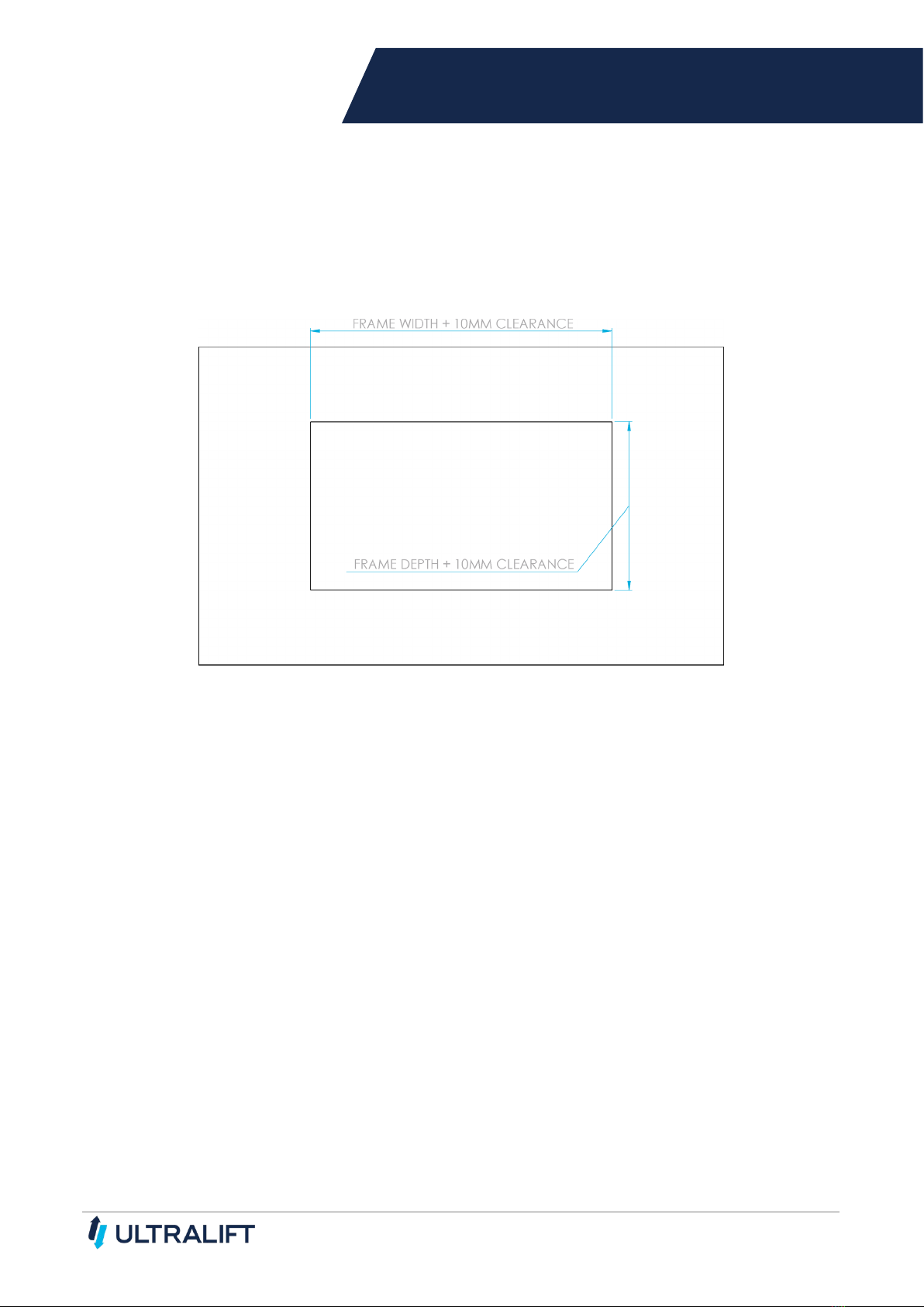
•After establishing the correct location for the lift and display panel, cut a hole in the ceiling at the size
listed on the following page.
•Organise a qualified trades person to frame up the roof to accommodate the Spartan so that it can be
mounted in the correct position.
•Route AV cables from the source to the roof location where the Lift will be in-stalled.
•Ensure that a double power point has been installed in the roof (or where suit-able) so that the Lift and
display panel can receive power.
•Before mounting the display panel to the Lift, ensure that it will suit the Lift in relation to dimensions,
loading capacity and functionality.
•Read instructions completely before proceeding. Follow instructions carefully. Installation contrary to
instructions invalidates warranty.
CAUTION
•Do not obstruct operation of lift with fingers or any object. Injury or damage could result.
•Check above the ceiling for obstructions (i.e., water pipers, cable, and duct work) before beginning
installation.
•Do not connect any power to the lift until installation is complete
•Attach the display panel only after the lift has been properly installed and tested.
•Unit operates on a 240V with a current draw of 1A and a 6.5mA standby.
•If adjusting the limits, do so prior to wiring into control systems.
•Organise your mounting hardware and have the necessary tools readily accessible before installation.
CHOOSE AN INSTALLATION METHOD:
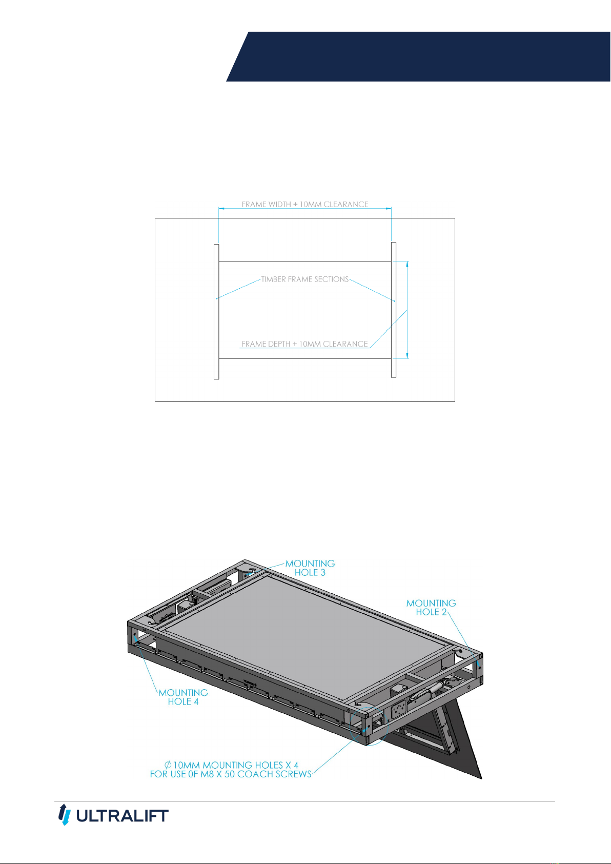
METHOD ONE:
Installing into Ceiling Cavity with Side Coash Screws
In this method, the unit is secured in place using coach screws on the sides of the frame and through
supporting timber (steel) beams.
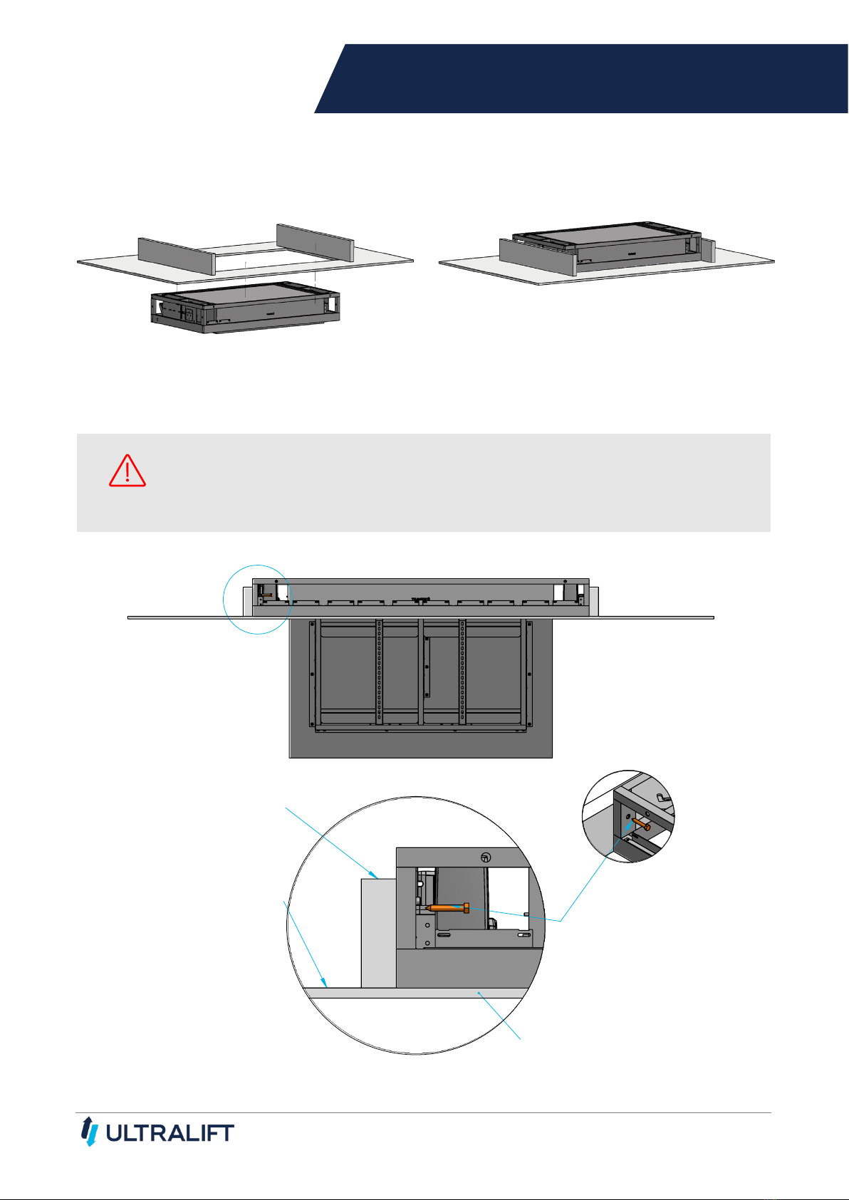
METHOD TWO:
Installing into Ceiling Cavity with Top Hanging Bolts
In this method, the unit is secured in place using all-thread bolt or DynaBolt and from the top side of
the frame.

7
INSTALLATION: METHOD 1
SPARTAN
INSTALLATION: METHOD 1
SECURING WITH COACH SCREWS
1. Mark out the ceiling cut-out as per minimum hole dimensions below. Please refer to the size table on
pages 6. Cut out the hole for lift to fit through.
2. Frame up the ceiling joists and timber frame using a qualified tradesperson.
3. Route the Audio-Visual cables to the lift position in the ceiling. See the Cable Management instructions to
be followed post install.
4. A double power point is required in the ceiling to power the Spartan and the display panel.
NOTE: Access to the power point in the ceiling is advisable.
5. Power the Spartan unit on the ground (using the Wiring Instructions) and open the screen tilt to
approximately 90°. (Enough for access to the roof panel and the inner section.)
6. Remove the side Trim Panels to allow access to the mounting holes.

8
INSTALLATION: METHOD 1
SPARTAN
7. Raise the Spartan unit into the pre-cut hole from the underside into position and line up with the pre-built
timber frame.
8. Ensure the bottom of the unit is flush with the ceiling plaster.
9. Secure the unit in place using the coach screws and through the mounting holes.
NOTE
Ensure the supporting timber frames are in parallel. When using this method of installation,
the lift’s frame can be pushed out of square if the screws are not tightened equally or the
supporting frames are not in parallel.
A
DETAIL
A
TIMBER FRAME
CEILING PLASTER
POSITION FRAME SUCH THAT
TRIM PANEL IS FLUSH WITH
CEILING PLASTER
COACH SCREWS, F IX TO
TIMBER FRAME

9
INSTALLATION: METHOD 2
SPARTAN
INSTALLATION: METHOD 2
SECURING WITH TOP HANGING BOLTS
1. Mark out the ceiling cut-out as per minimum hole dimensions below. Please refer to the size table on
pages 6. Cut out the hole for lift to fit through.
2. Route the Audio-Visual cables to the lift position in the ceiling. See the Cable Management instructions to
be followed post install.
3. A double power point is required in the ceiling to power the Spartan and the display panel.
NOTE: Access to the power point in the ceiling is advisable.
4. Raise the Spartan unit into the pre-cut hole from the underside into position.
5. Ensure the bottom of the unit is flush with the ceiling plaster.
6. Secure the unit in place using bolts and through the mounting holes.

10
INSTALLATION: METHOD 2
SPARTAN
FRAME WIDTH -186MM
FRAME DEPTH - 126MM
AA
4 x ROOF MOUNTING PLATES
B
SECTION
A-A
DETAIL
B
ALLTHREAD OPTION
LOCKING
NUTS
ALLTHREAD
DYNABOLT OPTION

11
POST-INSTALLATION:
SPARTAN
POST-INSTALLATION:
1. Route the AV cables into the lift, through cut-out provided for cable management. (See Cable
Management section)
2. If using IR Controller, expose the IR eye in a suitable position to achieve line of sight to the remote.
3. Once Spartan unit is safely secured, refit any removed panels, in reverse order as you took it apart.
4. Extend the plaster to fill the gaps up to the trim panel and around the ceiling cut-out and paint as
necessary.
25
PLASTER TO EDGE
OF TRIM PANEL
170
PLASTER TO EDGE
OF TRIM PANEL
VIEW FROM ROOM
(DIMMENSIONS NOT TAKING INTO ACCOUNT SIDE CLEARANCES)
PLASTER
INFILL AREA
CEILING
PLASTER

12
POST-INSTALLATION:
SPARTAN
B
SIDE CUT AWAY VIEW
(BLUE = PL A STER INFILL A REA )
A
FRONT CUT AWAY VIEW
(BLUE = PL A STER INFILL A REA )
170
DETAIL
A
FRONT
TRIM PANEL
CEILING
PLASTER
25
13
STANDARD PLASTER
DETAIL
B
SIDE
TRIM PANEL
CEILING
PLASTER

13
CABLE MANAGEMENT
SPARTAN
CABLE MANAGEMENT
1. Connect cables (blue) to the display panel and run-down cable management arms as per diagram below.
Make use of Cable Ties provided as indicated in the diagram below (black lines). There is a small
clearance between the frame members and the timber closure panel, allowing the use of the Cable Ties.
2. Be sure to allow the extra cable length on the cable management arm. Be careful to avoid potential
pinching of cables, particularly around the cut-out area.
3. Reconnect power to the lift.
Please Note: Cables must be securely attached to the frame to avoid pinching of the cables. Raise and lower
the lift several times using the controller, closely watching the cables to make sure they do not interfere with
the lift operation. The Installer is responsible for ensuring the cables do not interfere with the mechanism as
the unit raises and lowers.
A
CABLE EXITS
FRAME
DETAIL
A
RUNNING CA BLE OUT A ND A LONG TILT FRA ME
CABLE TIE POINT

14
CABLE MANAGEMENT
SPARTAN
B
DETAIL
B
RUNNING CA BLE THROUGH HOOP
CABLE MUST PASS
THROUGH HOOP

15
MOUNTING THE TV
SPARTAN
MOUNTING THE TV
CAUTION
The screen should only be fitted to the lift when installation of the Spartan has been
completed. The Installer is responsible for ensuring that the lift is properly secured in the
ceiling.
1. Connect power to the lift and lower lift using the controller.
2. Disconnect power to the lift.
3. Remove the Mount Rails by loosening the two 5mm locking screws.
4. Fit the rails to the back of the screen and bolt using the four Phillips head screws and washers, as per
diagram below, noting the orientation from the top of the TV to the top of the rails.
5. Lift the TV and hook rails onto the lift.
6. Tighten the locking screws to lock the rails into position, ensuring that the screws are tight.
7. Ensure the TV is mounted centrally.
8. Ensure the TV is not sticking out of the door panel.

16
MOUNTING THE TV
SPARTAN
A
B
DETAIL
A
DETAIL
B
VERTICAL RAILS LOCKED
IN PLACE WITH LOCKING SCREW
VERTICAL RAILS SLOT
OVER HORIZONTAL RAILS

17
WIRING DIAGRAM
WIRING DIAGRAM
The wiring diagram shown below is the standard wiring arrangement for Ultralift’s Linear-Motor Driven
products including Atlas, Phoenix, Titan, and Spartan range.
This should not need to be changed unless swapping to an integrated automation setup using contact closure.
Ports and their uses:
•AC: 240 V, 50-60 Hz, 200 W
•A1 & A2: Parallel Controller Ports (Bluetooth, IR, or Dry Contact Closure for automation)
•1, 2, 3: Actuator/Column 1, 2, and 3 Ports
POWER CABLE
240 V IN
ACTUATOR 1 PORT
ACTUATOR 2 PORT
IR EXTENSION CABLE
DP1U CONSOLE
ULTRALIFT IR
CONTROLLER
(UIRC)
A1 PORT
A2 PORT

18
OPERATION
OPERATION
TO SET TRAVEL LIMITS:
1. Use the DP1U controller “Up” and “Down” buttons to drive the lifter to the desired up limit position.
2. Once the desired up limit travel has been reached press “S” then “1” within two seconds. This saves
the up limit to the lift controller. Holding “1” should now drive the lift to the saved up limit.
3. Use the DP1U controller “Up” and “Down” buttons to drive the lifter to the desired down limit position.
4. Once the desired down limit travel has been reached press “S” then “2” within two seconds. This
saves the down limit to the lift controller. Holding “2” should now drive the lift to the saved down limit.
5. The infrared remote will now control the lift between the set limits.
LEARNING A NEW REMOTE:
To learn a new remote handset, point the remote at the IR receiver then press and hold the stop “ - “ button
for 10 seconds.
DP1U Infrared Remote Ultralift UIRC
IMPORTANT
The lift should not be run up and down more than 4 times, or continuously at full load for
more than 1 minute without a 10-minute break.
Overheating will damage the Control Box.

19
OPERATION: AUTOMATION
Your product can be integrated into most control systems using dry contact relays. These instructions are
provided for Automation specialist reference only. Please contact us, or an Automation specialist, before
attempting this change.
If your existing product does not have a DP1U Controller:
•Unplug and remove the original controller and replace it with a DP1U Controller. This is needed as
removing the original controller will remove any stored Up or Down limits. DP1U is used to set the Up
and Down limits in the main control unit.
•On the DP1U, press the UP arrow to bring to the desired height. Press the DOWN arrow to stop.
Press the S button and within 2 seconds press the 1 button. Memory 1 is now set.
•Repeat procedure for other Memory positions.
TO AUTOMATE:
Plug in a standard CAT category LAN cable between the Control unit port A1 (or A2) and external relays. Use
the pinouts below to activate the desired action. Note: The lift will only travel to the memory position while the
relay is held.
STOP FUNCTION:
There is not dedicated stop pin-out. They relays operate the lift as long as they are closed. To stop the lift,
release the relay contact.
CONTROL BOX PINOUT:
Function Pins Colour (T568A) Colour (T568B)
Up 4 & 5 Blue & Blue/White Blue & Blue/White
Down 4 & 8 Blue & Brown Blue & Brown
Store 2 & 8 Green & Brown Orange & Brown
Memory 1 3 & 5 Orange/White &
Blue/White
Green/White & Blue/White
Memory 2 3 & 8 Orange/White & Brown Green/White & Brown
Memory 3 2 & 5 Green & Blue/White Orange & Blue/White

20
OPERATION: AUTOMATION
The product can also be integrated using infrared emitter or universal remote products. When using these
codes, the “LEARNING A NEW REMOTE” procedure should be followed.
The Ultralift UIRC has a built-in infrared receiver located behind the small hole on the side of the box to
accommodate adhesive backed infrared emitters without using the infrared eye extension.
PRONTO HEX CODES:
Up
0000 0068 0000 0032 00C8 0018 0010 0030 0030 0010 0030 0010 0010 0030 0010 0030 0010 0030
0030 0010 0010 0030 0010 0030 0010 0030 0010 0030 0030 0010 0010 0030 0010 0030 0010 0030
0010 0030 0010 0030 0010 0030 0010 0030 0030 0010 0010 0030 0010 0030 0010 0030 0010 0030
0010 0030 0010 0030 0010 0030 0010 0030 0010 0030 0010 0030 0010 0030 0030 0010 0010 0030
0010 0030 0010 0030 0010 0030 0010 0030 0010 0030 0010 0030 0010 0030 0010 0030 0010 0030
0010 0030 0010 0030 0030 0010 0010 0030 0030 0010 0030 0010 0010 04E2
Down
0000 0068 0000 0032 00C8 0018 0010 0030 0030 0010 0030 0010 0010 0030 0010 0030 0010 0030
0030 0010 0010 0030 0010 0030 0010 0030 0010 0030 0030 0010 0010 0030 0010 0030 0010 0030
0010 0030 0010 0030 0010 0030 0010 0030 0030 0010 0010 0030 0010 0030 0010 0030 0010 0030
0010 0030 0010 0030 0010 0030 0010 0030 0010 0030 0010 0030 0010 0030 0030 0010 0010 0030
0010 0030 0010 0030 0010 0030 0010 0030 0010 0030 0010 0030 0010 0030 0010 0030 0030 0010
0010 0030 0010 0030 0010 0030 0010 0030 0030 0010 0030 0010 0010 04E2
Stop
0000 0068 0000 0032 00C8 0018 0010 0030 0030 0010 0030 0010 0010 0030 0010 0030 0010 0030
0030 0010 0010 0030 0010 0030 0010 0030 0010 0030 0030 0010 0010 0030 0010 0030 0010 0030
0010 0030 0010 0030 0010 0030 0010 0030 0030 0010 0010 0030 0010 0030 0010 0030 0010 0030
0010 0030 0010 0030 0010 0030 0010 0030 0010 0030 0010 0030 0010 0030 0030 0010 0010 0030
0010 0030 0010 0030 0010 0030 0010 0030 0010 0030 0010 0030 0010 0030 0010 0030 0010 0030
0030 0010 0010 0030 0010 0030 0010 0030 0030 0010 0030 0010 0010 04E2
DPU1 CONTROLLER STANDARS CAT LAN CABLE
Table of contents