808 Gilman Street Berkeley, CA., 94710 p:925.253.2960 www.ultraviewcorp.com
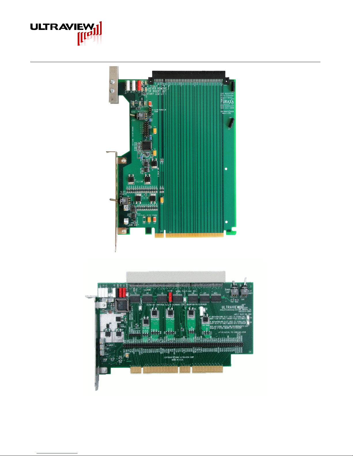
If the PCIEXT64U/UB is plugged into a motherboard slot that has a 5V signaling environment, the
“LIKELY SIG. ENV 5V” LED on the extender should light up. In this case, you may only plug in either a
board-undertest designed for a 5V signaling environment or a universal board-under-test. The
PCIEXT64UB’s PCI connector prevents a 3.3V-only board from being inserted, and the connector’s
web ensures correct socket alignment, even with UUTs with out-of-spec gold finger contact areas. It
only allows a 5V or Universal (3.3V and 5V capable) board to be inserted. In the rare case that you
have a 3.3V-only board-under-test, the Ultraview PCIEXT64U must be used, but that model is not
recommended for most high-volume applications, due to the ability for some boards-under-test to be
installed in a misaligned manner.
If the PCIEXT64U or UB is plugged into a motherboard slot that has a 3V signaling environment, the
“LIKELY SIG ENV 3V” LED should light up. In this case, you may only plug in either a board-under-test
designed for a 3V signaling environment, or a universal UUT. In rare cases you may be also able to
insert a board with 5V signaling environment (despite the PCIEXT64U or UB being installed in a 3V
slot), but only in cases in which you can be absolutely sure that the board-under-test does not use VIO
internally, and does not connect it to any other power supply plane. Even in that case, there is a risk of
damaging the board-under-test, so this should only be tried with prototype boards that are expendable.
External Power: (Optional and Risky)
- USE EXTREME CAUTION! -
Slot Power switch must remain in OFF position, and computer system
must remain ON, when using this mode or damage to system may result.
An external power supply can be used to provide the plug- in UUT power by use of the 5V, +/- 12V,
VIO and 3.3V test point connectors. The Slot Power switch MUST remain off when an external power
supply is connected to power points. Special care must be taken with an external power supply, as
power provided to the plug-in UUT is not current limited. Also, if the external +5V (and +3V if used) are
below +4.75V and +2.7V respectively, the bus switches will not turn on, and the
UUT will not be accessible to the system. While the use of an external power supply is valuable for
voltage margin testing of UUTs, it must be done with care. Use a multi-output external power supply
whose voltages all turn on and off as close to simultaneously as possible. Before removing the UUT,
be sure to save the UUT’s configuration registers using the live-insertion software, and then turn off the
external power supply. The computer must remain ON. The bus switches on
the PCIEXT64U or UB will automatically disconnect the UUT from the motherboard when the external
5V (and 3.3V, if present) fall below the 4.7V and 2.7V thresholds, respectively. Then, remove your
UUT, and replace it with another, just as you would do normally. When you are ready to start up your
new UUT, turn on the external power supply (not the slot power switch). Then, reinitialize the
configuration registers, using the live insertion software, and begin to use the new UUT.
Remember that the SLOT POWER switch on the PCIEXT64U or UB must always remain off
when using external power. It must never be turned on!
r1v05 Page 8 of 19 Copyright © 2008 – 2010 Ultraview Corporation