Ultravolt 60W User manual

GENERAL INFORMATION:
This High Power line of high-voltage regulated DC to DC
converters is an extension of the “C” Series, directly addressing
the high power density needs of >30 watt applications. High
Power “C” units provide up to 60/125/250 watts. This high
power density is especially suited to high-energy systems with
large capacitances, fast repetition rates, or high continuous-
DC-power requirements. See Application Note 10 for more
charging information.
COMPATIBILITY:
The High Power “C” Series matches the standard 30 watt
“C” Series for design methodology, wide input range, remote
control, enable/disable, and reference.
LOW VOLTAGE INPUT:
The input is a dual row, 7 pin IDC header. The first row has
the same pin out & signals as the 30 watt “C” Series. The
second row provides the pins required to support the High
Power “C” Series version. Connections can be made via
J-hooked and soldered leads, or via AMP MOD-U connectors
with high-pressure, high-current pins. See Application Note
3. A direct-mounted PCB with header sockets, such as the
UltraVolt interface board, can mate to the chassis-mounted
power supply’s input header. Seven #4-40 and two #2-56
PEM nuts are provided on the top cover for this purpose. The
250 watt models also feature a four-pin, high-current input
power connector.
HIGH VOLTAGE OUTPUT:
The High Power “C” Series is a non-isolated, unipolar
converter. Positive or negative output must be specified.
Output is adjustable from 0 to 125V, 250V, 500V, 1kV,
2kV, 4kV or 6kV on all 60W/125W/250W units. Additionally,
60W/125W models are adjustable from 0 to 8kV, 10kV, 12kV
or 15kV. As the output voltage is reduced towards 0, the
maximum current capability remains unchanged. Internal
capacitance is kept to a minimum to facilitate fast-rise
applications. Most fast-rise applications involve charging a
storage capacitor, which also acts as an additional output
filter/storage capacitor. If your application is continuous DC
bias power, an external filter/storage capacitor should be
added. Contact UltraVolt’s customer service department for
recommended capacitor values.
OUTPUT VOLTAGE MONITOR:
A 100 MegWdivider provides a 100:1 voltage monitor on
models up to 6kV. On models 8kV and higher a 1 GigW
divider provides a 1000:1 test point. The monitor has an
output impedance of 1.1 MegWand is calibrated for use
with a 10 MegWinput impedance meter. Overall accuracy is
+/-2.0% with a temperature coefficient of +/-200 ppm per °C.
For applications requiring a different scale factor, such as an
ADC compatible design, an external resistor may be added in
parallel with the output.
OUTPUT CURRENT MONITOR:
The High Power “C” Series is equipped with an output current
monitor. Current from the high-voltage multiplier can be
monitored by reading the voltage generated between Output
Monitor pin 3 and Signal Ground pin 5. The monitor has an
output impedance of 5.1 k
W
. Internal voltage dividers create a
small linear offset voltage.
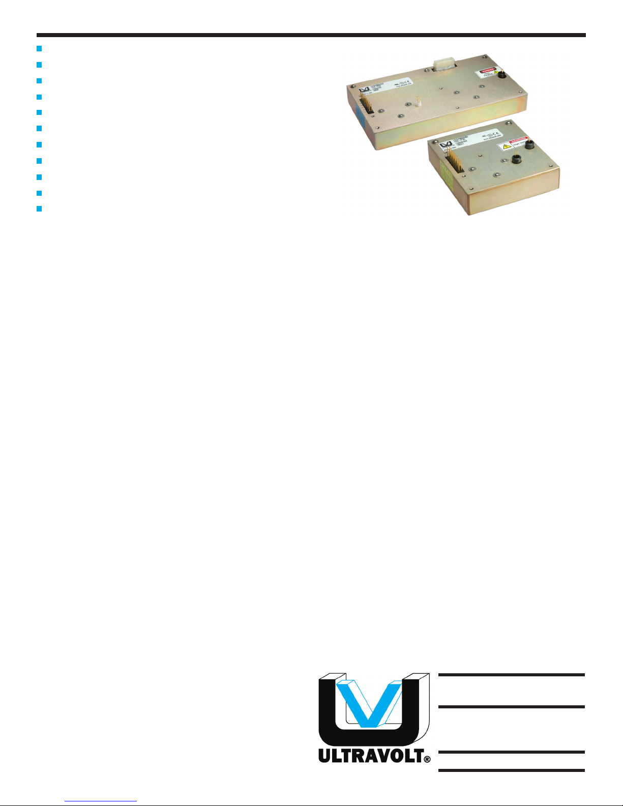
MECHANICAL:
The High Power “C” Series converters are packaged in
chassis-mount aluminum enclosures, mounted using the
four #8-32 studs and thermal interfacing material. Electrical
connections are via wiring harness or top cover mounted
PCB. The 60W/125W units up to 6kV utilize the standard 19
in3enclosure. The 60W/125W units 8kV and higher use the
extended 38 in3enclosure along with the 250W units up to
6kV. See Application Note 6 for thermal considerations and
mounting configurations.
ENVIRONMENTAL:
The High Power “C” Series provides full power at case
temperature from -40 to +65°C. Extended temperature range
is available along with other enhanced capabilities. Please
contact the factory. All units receive a 24 hour burn in prior to
final testing.
7 models from 0 to 125 Volts through 0 to 6kV
60, 125, or 250 watts of output power
Maximum Iout capability down to 0 Volts
Maximum Iout during charge/rise time
Output short-circuit protection
Very fast rise with very low overshoot
High power density
Output current & voltage monitors
>200,000 hour MTBF @65°C
Fixed-frequency, low-stored-energy design
UL, cUL, IEC-60950-1, and Demko Recognized
HIGH POWER “C” SERIES
HIGH VOLTAGE POWER SUPPLY
19
1800 OCEAN AVE., FRNT
RONKONKOMA, NY 11779
TEL 800-9HV-POWER
TEL 631-471-4444
FAX 631-471-4696
www.ultravolt.com
“Making High Voltage Easier!”
®

Typical Characteristics:
HIGH POWER “C” SERIES
HIGH VOLTAGE POWER SUPPLY
Specifications subject to change without notice
TEL 800-9HV-POWER or 800-948-7693 or 631-471-4444 FAX 631-471-4696www.ultravolt.com
1800 Ocean Ave., Frnt, Ronkonkoma, NY 11779
“Making High Voltage Easier!”
®
20
Parameter Conditions Models Units
Input: All Types
Voltage Range Full Power + 23 to 30 VDC
Voltage Range Derated Power Range + 11 to 32 VDC
Current Standby / Disable < 40 mA
Current Max Load, Extended Input Voltage Figures A & B Graph
AC Ripple Current Nominal Input, Full Load < 50 mA p-p
Output: 1/8C 1/4C 1/2C 1C 2C 4C 6C
Voltage Range Nominal Input 0 to 125 0 to 250 0 to 500 0 to 1,000 0 to 2,000 0 to 4,000 0 to 6,000 VDC
Power Nominal Input, Max Eout 60 125 250 60 125 250 60 125 250 60 125 250 60 125 250 60 125 250 60 125 250 Watts
Current Iout, Entire Output Voltage Range 480 1000 2000 240 500 1000 120 250 500 60 125 250 30 62 125 15 31 62 10 21 42 mA
iMon Scale Factor Full Load 400 833 1667 200 417 833 208 208 417 50 114 227 26 52 104 11.5 26 52 6.2 17.7 35 mA/V
Ripple Full Load, Max Eout, Cload ≥0.5uF < 1.0 < 1.0 < 1.0 < 1.0 < 1.0 < 1.0 < 1.0 V p-p
Overshoot C Load, 0 Eout to Full Eout < 1V < 1V < 1V < 1V < 1V < 1V < 1V V pk
Voltage Derating Max Iout, Extended Input Voltage Figure C Graph
Rise Time Max Iout, Various C Loads & Eouts Figures D & F Table
Line Regulation Nom. Input, Max Eout, Full Power < 0.01% VDC
Static Load Regulation
No Load to Full Load, Max Eout < 0.01% VDC
Stability 30 Min. warmup, per 8 hr/ per day < 0.01% / < 0.02% VDC
Output Voltage Monitor: All Types
Voltage Full Eout Range, Full Iout Range 10.00 V per kV
Proportionality Full Eout Range, Full Iout Range ± 0.08% V per kV
Remote Programming: All Types
Input Impedance Nominal Input + Output Models 1.1MΩ to GND, - Output Models 1.1MΩ to +5 Vref MΩ
Adjust Resistance Typical Potentiometer Values 10K to 100K (Pot across Vref. & Signal GND, Wiper to Adjust) Ω
Adjust Linearity 0% to 100% Figure E Graph
Adjust Voltage Referenced to signal ground Figure E (0 to +5 VDC) Graph
Adjust Logic 0 to +5 for +Out, +5 to 0 for -Out +4.64 VDC for +Output or +0.36 for -Output = Nominal Eout
Reference: All Types
Output Voltage T=+25°C, Initial Value + 5.00 ± 2% VDC
Output Impedance T=+25°C 464 ± 1% Ω
Stability Over Full Temperature Range See “A” Series Datasheet Figure F Graph
Enable: All Types
Power Supply On Floated, or voltage ≥ TTL High +2.4 to 32 VDC
Power Supply Off Grounded, or voltage ≤ TTL Low 0 to + 0.7 ± 0.2 (Isink 1mA minimum) VDC
Temperature & Humidity: All Types
Humidity All Conditions, Standard Package 0 to 95% non-condensing
Operating Full Load, Max Eout, Case Temp. -40 to +65 °C
Storage Non-Operating, Case Temp. -55 to +105 °C
Coefcient Over the Specied Temperature ± 50 PPM / °C
Thermal Shock Mil-Std 810, Method 503-4, Proc. II -40 to +65 °C
Altitude: All Types
All Conditions Standard Package Sea Level through Vacuum
Shock & Vibration: All Types
Shock Mil-Std-810, Method 516.5, Proc. IV 20 G’s
Vibration
Mil-Std-810, Method 514.5, Fig. 514.5C-3
10 G’s
Packaging: 60W/125W 250W
Material Outer construction Aluminum Alloy 5052-H32, Finish: Mil-C-5541 Class 1A Aluminum Alloy 5052-H32, Finish: Mil-C-5541 Class 1A
Length Not including pins or mounting pts 4.00 ± 0.025 (101.6±.6) 8.00 ± 0.025 (203.2±.6) In (mm)
Width Not including pins or mounting pts 4.50 ± 0.025 (114.3±.6) 4.50 ± 0.025 (114.3±.6) In (mm)
Height Not including pins or mounting pts 1.075 ± 0.025 (27.3±.6) 1.075 ± 0.025 (27.3±.6) In (mm)
Volume Not including pins or mounting pts 19.35 (317) 38.7 (634) In³ (cc)
Weight Overall 1.4 (.64) 2.6 (1.18) Lbs (kg)

Typical Performance Characteristics:
Fig. D
Rise Time Formulas
Fig. F
Internal Storage Capacitance
I
F =
C xV
C xE2
J =
2
C xV
T =
I I = C xV xF
C = uF
V = Volts
I = mA
T = mS
C = uF
V = kV
I = mA
F = Hz
C = uF
V = kV
I = mA
F = Hz
C = uF
E2= kV
J = Ws
NOTES:
Capacitance must include HVPS internal Capacitance, see Fig. F.
For very light capacitive loads the HVPS exhibits slower than
calculated rise times due to the pulse by pulse current limit.
HIGH POWER “C” SERIES
HIGH VOLTAGE POWER SUPPLY
TEL 800-9HV-POWER or 800-948-7693 or 631-471-4444 FAX 631-471-4696www.ultravolt.com
1800 Ocean Ave., Frnt, Ronkonkoma, NY 11779
“Making High Voltage Easier!”
®
21
INPUT VOLT A GE
% EFFICIENCY
Fig. A
DC Efficiency vs. Input Voltage Range
% OUTPUT VOLTAGE
REMOTE ADJUST VOLTAGE
– OUTPUT
+ OUTPUT
Fig. E
Remote Control Characteristics
INPUT CURRENT (AMPS)
INPUT VOLT A GE
Fig. B
Input Current vs. Input Voltage Range
Fig. C
Output Voltage vs. Extended Input Voltage
(Up to 65°C Chassis Mount w/o Heatsink)
20 25 30
10 15
% OUTPUT VOLTAGE
INPUT VOLT A GE
20W 1/4 Load
20W 1/2 Load
20W Full Load
Voltage Derating
Thermal Derating
PCB
Mount w/o
Heatsink @65°C
Model 60W 125W 250W
1/8C 0.90 uF 0.90 uF 1.80 uF
1/4C 0.90 uF 0.90 uF 1.80 uF
1/2C 0.43 uF 0.43 uF 0.85 uF
1C 0.019 uF 0.019 uF 0.038 uF
2C 0.019 uF 0.019 uF 0.038 uF
4C 0.013 uF 0.013 uF 0.026 uF
6C 0.013 uF 0.013 uF 0.026 uF

Connections High Power Pin Connections
(250 watt units)
METAL CASE
CONSTRUCTION:
Aluminum box
Chem film per MIL-C-5541
Class 1A
TOLERANCE:
Overall ±0.025” (0.64)
Pin to Pin ±0.015” (0.38)
Hole to Hole location ±0.025” (0.64)
MOUNTING:
Bottom mounting, 8-32 x 0.440 (11.18)
long threaded stud
HIGH POWER “C” SERIES
HIGH VOLTAGE POWER SUPPLY
Copyright 1991-2009, UltraVolt, Inc.
Rev. P 7/09
www.ultravolt.com
1800 Ocean Ave., Frnt, Ronkonkoma, NY 11779
“Making High Voltage Easier!”
®
Example: 1/2C24-P125
Voltage
Model
Input
Power
Polarity
Type
Ordering Information
22
IEC-60950-1
Downloadable drawings (complete with mounting
& pin information) and 3D models are available online
at: www.ultravolt.com/drawings.htm
1 & 8 - Input Power Ground Return
3 - Iout Monitor
4 - Enable/Disable
5 - Signal Ground Return
6 - Remote Adjust Input
7 - +5 VDC Reference Output
2, 9 & 10 - Positive Power Input
11 - N/C
12 - N/C
13 - N/C
14 - Eout Monitor
15 & 16 - HV Ground Return
17 & 18 - HV Output
All grounds joined internally. Power-
supply mounting points isolated from
internal grounds by >100kW, .01uF /
50V (Max)
2, 9 & 10 - N/C
19 - Positive Power Input
20 - Positive Power Input
21 - Input Power Ground Return
22 - Input Power Ground Return
Type: 0 to 125 VDC Output 1/8C
0 to 250 VDC Output 1/4C
0 to 500 VDC Output 1/2C
0 to 1,000 VDC Output 1C
0 to 2,000 VDC Output 2C
0 to 4,000 VDC Output 4C
0 to 6,000 VDC Output 6C
Input: 24VDC Nominal 24
Polarity: Positive Output -P
Negative Output -N
Power: 60 Watts Output 60
125 Watts Output 125
250 Watts Output 250
Heat Sink: .400” High (Sized to Fit Case) -H
This manual suits for next models
2
Table of contents