Ulvac TM201 User manual

SK00-6740-DI-002-03
No.170821
INSTRUCTION MANUAL
OIL MIST TRAP
MODEL
TM201
TM401
Components division
ULVAC, Inc.
Read this manual before operation and keep it at your
hand for immediate reference

-i-
Table of Contents
1. INTRODUCTION ・・・・・・・・・・・・・・・・・・・・・・・・・・・・・・・・・・・・・・・・・・・・・・・・・・・・・・・・ 1
2. GENERAL DESCRIPTION ・・・・・・・・・・・・・・・・・・・・・・・・・・・・・・・・・・・・・・・・・・・・・・・・ 2
2.1 Features ・・・・・・・・・・・・・・・・・・・・・・・・・・・・・・・・・・・・・・・・・・・・・・・・・・・・・・・・・・・・・・ 2
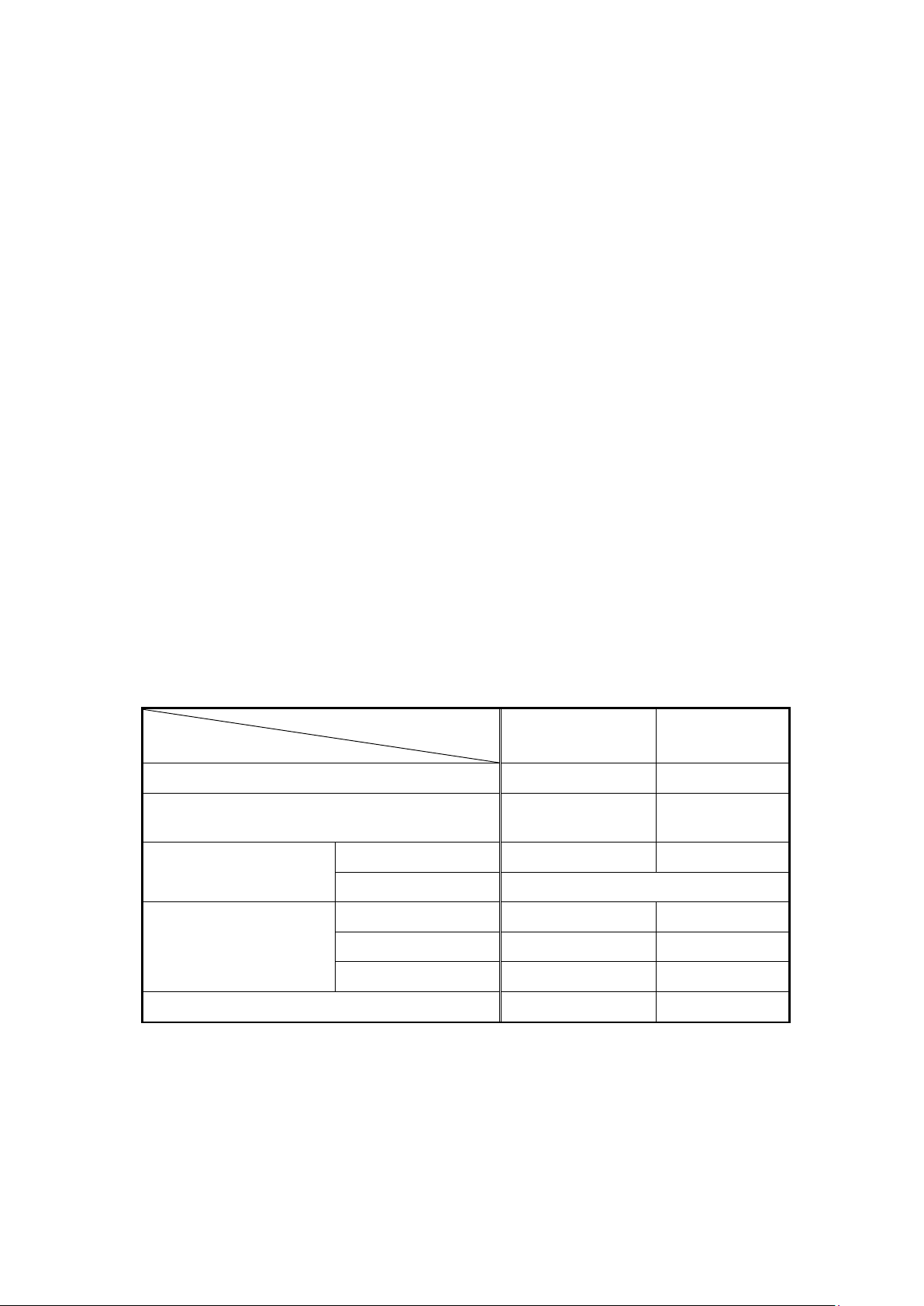
2.2 Specifications ・・・・・・・・・・・・・・・・・・・・・・・・・・・・・・・・・・・・・・・・・・・・・・・・・・・・・・・・・ 2
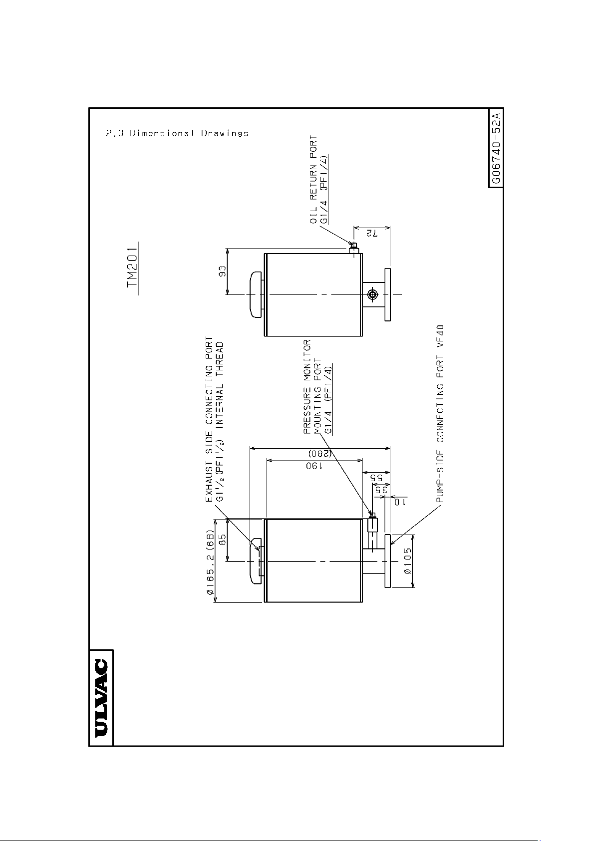
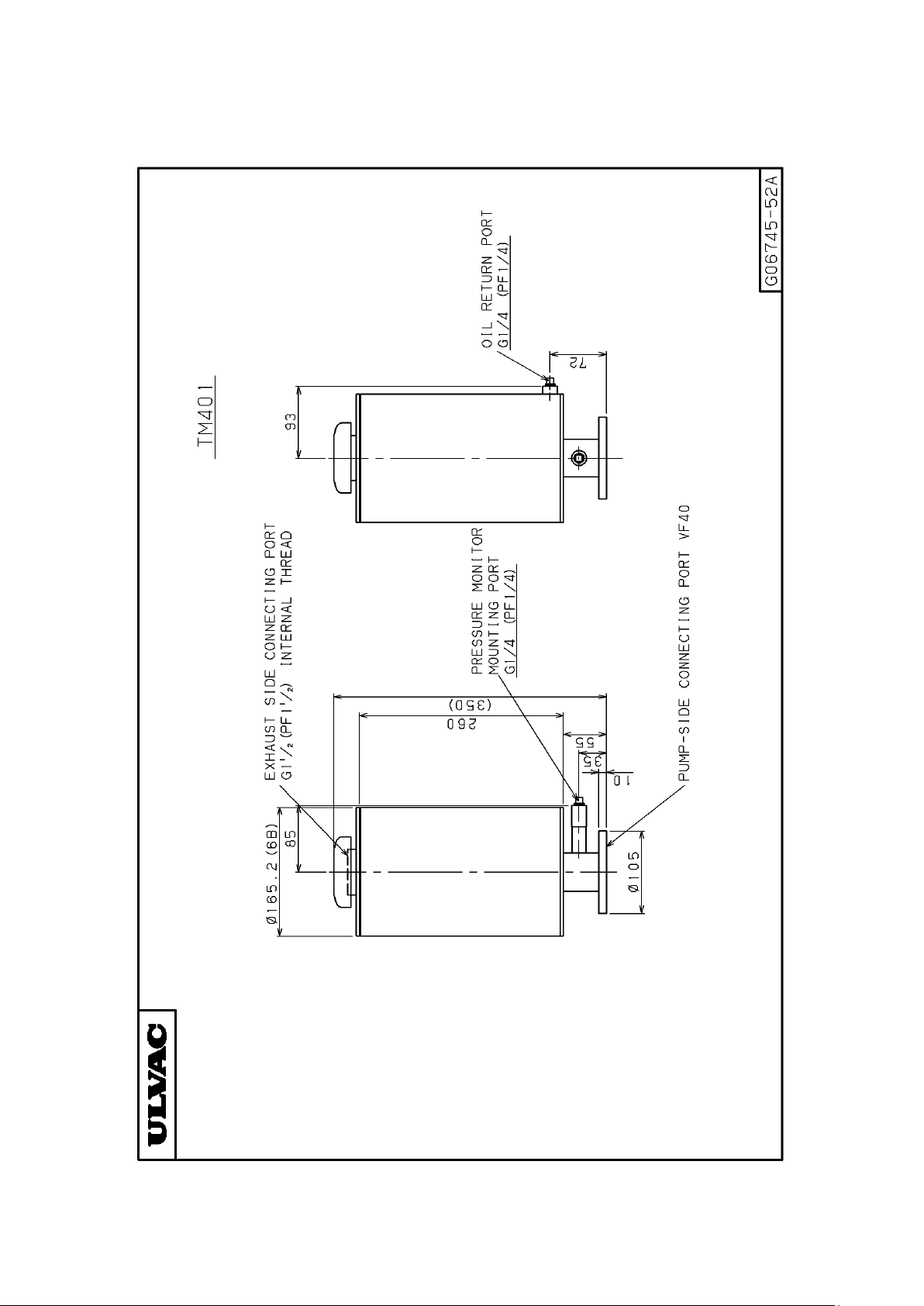
2.3 Dimensional Drawings ・・・・・・・・・・・・・・・・・・・・・・・・・・・・・・・・・・・・・・・・・・・・・・・・・ 3
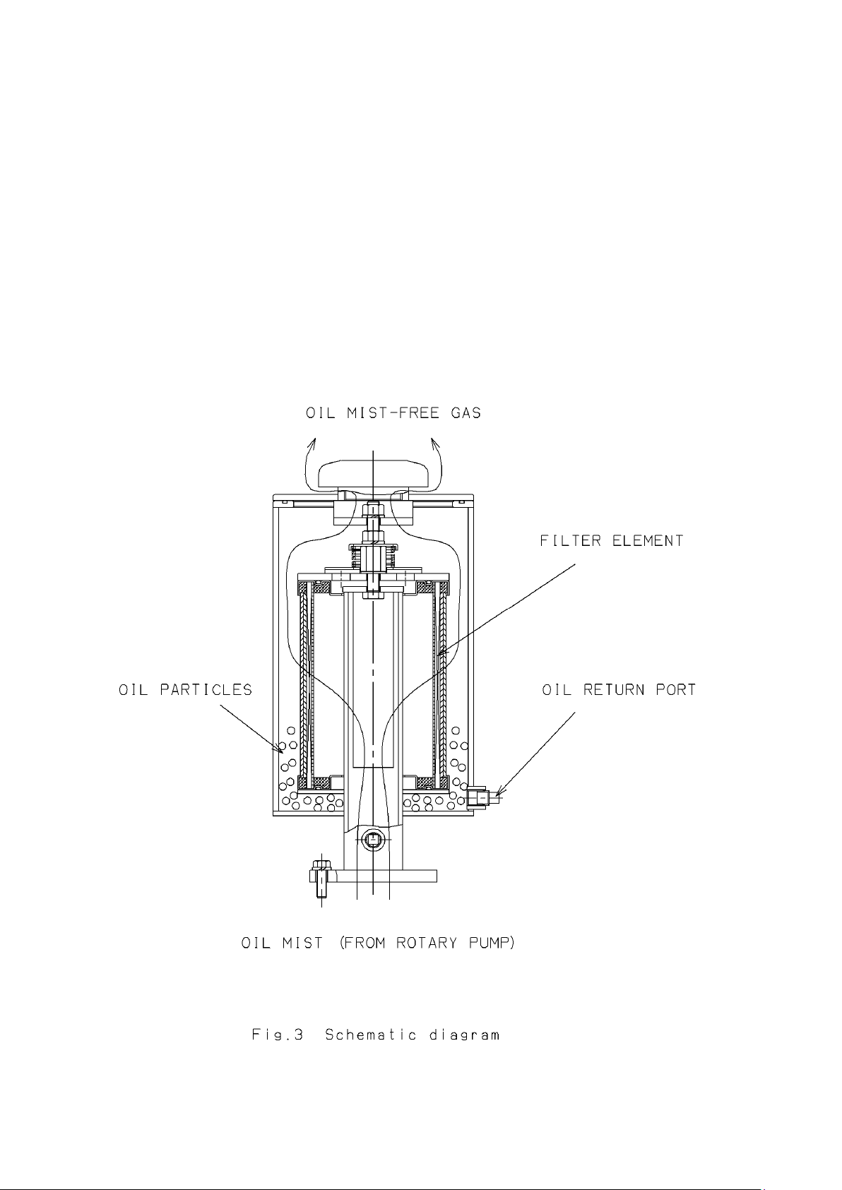
2.4 Structure ・・・・・・・・・・・・・・・・・・・・・・・・・・・・・・・・・・・・・・・・・・・・・・・・・・・・・・・・・・・・・ 5
3. OPERATION ・・・・・・・・・・・・・・・・・・・・・・・・・・・・・・・・・・・・・・・・・・・・・・・・・・・・・・・・・・・・・ 6
3.1 Check ・・・・・・・・・・・・・・・・・・・・・・・・・・・・・・・・・・・・・・・・・・・・・・・・・・・・・・・・・・・・・・・・ 6
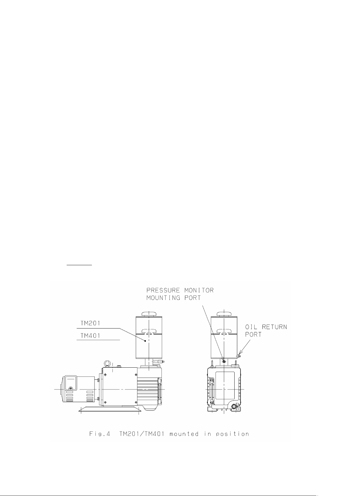
3.2 Mounting on Pump ・・・・・・・・・・・・・・・・・・・・・・・・・・・・・・・・・・・・・・・・・・・・・・・・・・・・ 6
3.3 Duct Piping ・・・・・・・・・・・・・・・・・・・・・・・・・・・・・・・・・・・・・・・・・・・・・・・・・・・・・・・・・・・ 6
3.4 Treatment of Trapped Oil ・・・・・・・・・・・・・・・・・・・・・・・・・・・・・・・・・・・・・・・・・・・・・・ 7
4. INSPECTION ・・・・・・・・・・・・・・・・・・・・・・・・・・・・・・・・・・・・・・・・・・・・・・・・・・・・・・・・・・・・ 8
4.1 Schedule Inspection ・・・・・・・・・・・・・・・・・・・・・・・・・・・・・・・・・・・・・・・・・・・・・・・・・・・ 8
4.2 Replacing the Filter Element ・・・・・・・・・・・・・・・・・・・・・・・・・・・・・・・・・・・・・・・・・・・ 8
4.2.1 Removing the filter element ・・・・・・・・・・・・・・・・・・・・・・・・・・・・・・・・・・・・・・・・ 8
4.2.2 Reassembling the filter element ・・・・・・・・・・・・・・・・・・・・・・・・・・・・・・・・・・・・・10
5. PRECAUTIONS ・・・・・・・・・・・・・・・・・・・・・・・・・・・・・・・・・・・・・・・・・・・・・・・・・・・・・・・・・・11
5.1 Clogging of Filter Element ・・・・・・・・・・・・・・・・・・・・・・・・・・・・・・・・・・・・・・・・・・・・・ 11
5.2 Pressure Relief Valve ・・・・・・・・・・・・・・・・・・・・・・・・・・・・・・・・・・・・・・・・・・・・・・・・・・ 11
5.3 When the pump is used continuously at a high intake pressure ・・・・・・・・・・・・ 11
5.4 When using Oil Mist for a Pump that exceeds Maximum Throughput ・・・・・・ 12
6. WARRANTY ・・・・・・・・・・・・・・・・・・・・・・・・・・・・・・・・・・・・・・・・・・・・・・・・・・・・・・・・・・・・・ 13
7. MAJOR REPLACEMENT PARTS ・・・・・・・・・・・・・・・・・・・・・・・・・・・・・・・・・・・・・・・・・・14
SERVICE CENTER

-ii-
Attached Tables and Illustrations
Fig. 1 Dimensional drawing (TM201) ・・・・・・・・・・・・・・・・・・・・・・・・・・・・・・・・・・・・・・・・・ 3
Fig. 2 Dimensional drawing (TM401) ・・・・・・・・・・・・・・・・・・・・・・・・・・・・・・・・・・・・・・・・・ 4
Fig. 3 Schematic diagram ・・・・・・・・・・・・・・・・・・・・・・・・・・・・・・・・・・・・・・・・・・・・・・・・・・・・ 5
Fig. 4 TM201/TM401 mounted in position ・・・・・・・・・・・・・・・・・・・・・・・・・・・・・・・・・・・・・ 6
Fig. 5 Exploded view of filter element ・・・・・・・・・・・・・・・・・・・・・・・・・・・・・・・・・・・・・・・・・ 9
Table 1 Specifications ・・・・・・・・・・・・・・・・・・・・・・・・・・・・・・・・・・・・・・・・・・・・・・・・・・・・・・・ 2
Table 2 Major Replacement Parts List ・・・・・・・・・・・・・・・・・・・・・・・・・・・・・・・・・・・・・・・・ 14

-1-
1. INTRODUCTION
Thank you for purchasing this oil mist trap. Prior to operating this oil mist
trap, read this manual carefully for optimum performance, and operate it correctly.
Note that incorrect operation may cause trouble of the oil mist trap.
Also keep this manual in your file so that you can refer to it when you come
across any question or trouble during operation.

-2-
2. GENERAL DESCRIPTION
2.1 Features
(1) Removal of oil mist with high efficiency
Approx. 90% of the oil mist discharged from an oil sealed rotary vacuum
pump can be removed, allowing the work environment to be kept free from
contamination with oil mist.
(2) Employment of cartridge type filter element
The cartridge type filter element can be easily replaced when it is clogged or
corroded.
(3) Pump internal pressure relief valve
If the filter element is clogged, the pressure in the pump will rise at start-up
of the pump or during pumping operation, which can be dangerous.
If the pressure in the pump rises above 0.03 MPa (0.3 kg/cm2) (gauge
pressure), the pressure relief valve will be activated to prevent the pump and
oil mist trap from being damaged.
2.2 Specifications
Table 1 Specifications
Model
Item TM201 TM401
Filter element TM201E TM401E
Displacement m3/h *1
(L/min)
24
(400)
48
(800)
Connecting part dia. Pump side VF40 *2 VF40 *2
Exhaust side G1 1/2 internal thread *3
Outside
dimensions (mm)
Overall height 280 350
Overall width 181 181
Diameter 165 165
Weight (kg) 8.5 10
*1) Throughput under atmospheric pressure.
*2) The flange is the JIS vacuum flange (JIS B 2290).
*3) Same as PF 1 1/2.

-3-

-4-

-5-
2.4 Structure (Refer to Fig. 3)
The gas discharged from the oil sealed rotary vacuum pump (air, nitrogen
gas, etc.) blows up the oil in the pump and is introduced to the oil mist trap
along with fine particles of oil blown up. These fine particles of oil (oil mist)
are trapped by the filter element when they pass through it and the condensed
large oil particles gather between the oil mist trap and the filter element and
are discharged through the oil return port.
Gas from which most part of the oil mist has been removed is discharged
through the exhaust port of the oil mist trap.

-6-
3. OPERATION
3.1 Check
The oil mist trap has been shipped after rigorous inspection at the factory,
but check upon the following unpacking it.
(1) Is the unit the correct model you ordered?
(2) Are accessories (instruction manual, parts you ordered) supplied with the
unit?
(3) Is any part damaged or missing and any screw or nut loosened in transit?
If you find any problem, contact your local ULVAC organization or
representative.
3.2 Mounting on Pump (Refer to Fig. 4)
To mount the oil mist trap on the pump, proceed as follows.
(1) Verify that the exhaust port, O-ring groove and oil mist trap (TM) flange
are free from scars and dust.
(2) Mount the O-ring (V55) to the exhaust port of the pump and tighten the TM
flange using an Allen screw (M8).
3.3 Duct Piping
The exhaust port of the oil mist trap has a cap as standard, but has a flange
(RF-11) for duct piping as option. Use it depending on your application.
CAUTION :
① The flange for the duct piping (RF-11) is equivalent to VG4O.

-7-
3.4 Treatment of Trapped Oil
The TM201/401 is designed to discharge the trapped oil to outside through
the oil return port. Recover the discharged oil in a container and return it to
the pump when the pump is operated under no load or at stop.
However, do not return the oil to the pump if the oiliness of the recovered
oil is lower than the new oil used in the pump or if the oil contains water, dust
or the like or if chemicals like acid is used.
It can be a cause of trouble of the pump.
CAUTIONS:
① If you do not dispose of the trapped oil, oil will stay between the
fitter element and the oil mist trap and oil mist will come out.
② It is recommended to replace a filter element once immersed in oil
because clogging tends to occur.
③ Do not connect the oil return port and the pressure monitor mounting
port by means of a vinyl hose or the like. Oil mist will not be trapped.

-8-
4. INSPECTION
4.1 Scheduled Inspection
Periodically measure the pressure in the pump with the optional pressure
monitor mounted to the pressure monitor mounting port.
Verify that the pressure at start of the oil sealed rotary vacuum pump or
immediately after evacuation of the vacuum chamber from atmospheric
pressure is 0.03 MPa (0.3 kg/cm2) (gauge pressure). If it is higher than 0.03
MPa (0.3 kg/cm2) (gauge pressure), it is necessary to replace the filter element
and check the pressure relief valve.
4.2 Replacing the Filter Element (Refer to Fig. 5)
If the filter element is clogged, replace it, as a rule.
4.2.1 Remove the filter element
(1) Stop the pump or put the pump under no-load operating condition
and loosen the Allen screw (M8) that fixes the oil mist trap to the
pump to remove the oil mist trap. (If piping is connected to the
exhaust side, remove it.)
(2) Loosen the hex nut (M10) at the center of the exhaust port to remove
the flange.
(3) Loosen the hex nut (M10) to remove the parts of the pressure relief
valve.
(4) Loosen the spacer nut to remove the filter keep plate.
(5) Remove the filter element.
This completes the removal of the filter element.
CAUTIONS:
① Before replacing the filter element, check if the interior of the oil
mist trap or the pressure relief valve is contaminated with dust or
foreign matter. If so, remove it by cleaning.
② The seal washer can not be reused.

-9-

-10-
4.2.2 Reassembling the filter element
(1) Ensure that the mounting surface of the filter element in the oil
mist trap is free from foreign matter and scars.
(2) Mount the filter element in the oil mist trap.
(3) Mount the filter keep plate in position.
(4) Mount the seal washer (M10) and fix the filter element using the
spacer nut.
(5) Mount the parts of pressure relief valve.
CAUTIONS:
① Tighten the hex nut (M10) until it comes into contact with the spacer
nut. (The pressure relief valve is activated at a pressure below 0.03
MPa (0.3 kg/cm2) (gauge Pressure).
(6) Mount the O-ring in the O-ring groove of the oil mist trap. (Apply a
thin uniform coat of vacuum grease until the luster of the O-ring
surface changes.)
(7) Mount the flange in position and tighten it with the hex nut (M10).
This completes the mounting of the filter element.

-11-
5. PRECAUTIONS
5.1 Clogging of Filter Element
Clogging of the filter element will raise the pressure in the pump and
may damage the pump parts or the filter element. Therefore, when using the
filter element in the following application, be sure to mount a pressure
monitor (optional) to monitor the pressure.
① When the pump is used for continuous evacuation at a high suction pressure
or continuous pumping of high temperature gas
The pump temperature rises and the oil viscosity lowers, tending to cause
clogging. In this case, a large volume of oil, discharged from the exhaust
port of the pump, will the trapped by the filter, but if the pump is operated
under the above operating conditions for an extended time, the oil deposited
on the fine fiber of the filter element will form oil film, leading to
clogging.
② When the pump is used to pump liquid with high viscosity or fine powder
at ambient temperature, it will be deposited on the fiber of the filter
element, leading to clogging.
③ When reaction products are generated
5.2 Pressure Relief Valve
This device is designed to operate when the pressure in the pump exceeds
the maximum continuous operating pressure of 0.03 MPa (0.3 kg/cm2) (gauge
pressure). If this valve is activated, the oil mist discharged from the
pump will not be trapped by the filter element, but will be discharged
directly through the exhaust port of the oil mist trap.
If this happens, replace the filter element with a new one.
5.3 When the pump is used continuously at high intake pressure
If the pump is operated continuously at a high intake pressure (6500 Pa
or more) for an extended time, the pump temperature will rise and the oil
viscosity will lower. This increases the amount of oil mist (including fine
oil drops) discharged through the exhaust port of the pump and tends to clog
the fitter element. Foreign matter sucked into the pump during evacuation
and the sludge generated by deteriorated oil can also be a cause of the
clogging of the filter element.

-12-
If the filter element is clogged and the pressure in the pump exceeds the
maximum continuous operating pressure of 0.03 MPa (0.3 kg/cm2) (gauge
pressure), the pressure relief valve will operate to lower the internal
pressure, but it is necessary to replace the filter element.
If it is necessary to replace the filter element frequently, the use of
an oil mist trap one class larger than the current one is recommended.
5.4 When using Oil Mist Trap for a Pump that exceeds Maximum
Throughput
Do not operate the pump continuously at a high intake pressure of 6500
Pa or more when the TM201 is used for a pump with a throughput of 20 m3/h
or more (30 m3/h, 40 m3/h) or when the TM401 is used for a pump with a
throughput of 40 m3/h or more (60 m3/h, 80 m3/h).
The pressure relief valve will operate and oil mist be generated even with
a new filter element. Also the life of the filter element will be extremely
shortened.
For more information, contact your local ULVAC organization or
representative.

-13-
6. WARRANTY
(1) The warranty period of this oil mist trap is one year from the date of delivery.
(2) Should the oil mist trap fail under normal operating condition during this
warranty period, its repair will be carried out free of charge.
The normal operating conditions are as follows.
a) Ambient temperature: 10℃to 40℃
b)Suction gas: Dry air or dry nitrogen (0℃to 40℃)
c) Operation in conformity with instruction manuals.
(3) Troubles caused by the following are out of warranty.
a) Acts of God and force majeure.
b) Special atmosphere, such as pollution or the like.
c) Operation not in conformity with the instruction manual.
(Specifications, maintenance, inspection and others.)
d) Troubles judged by ULVAC engineer to be attributable to operating conditions
not appropriate for this oil mist trap.

-14-
7. MAJOR REPLACEMENT PARTS
Table 2 Major Replacement Parts List
No. Description Material Q'ty Remarks
1 Filter element 1 set TM201 : TM201E
TM401 : TM401E
2 O-ring (G145) NBR 1 JIS B 2401
3
Seal washer (M10) NBR 1
The exhaust port of the TM201 and TM401 are provided with the following.
Standard type : Cap
Option : RF-11 (equivalent to VG40)
This manual suits for next models
1
Table of contents
Popular Water Filtration System manuals by other brands

GE
GE GXWH40L installation instructions

SunSun
SunSun HW-302 quick start guide

Auga
Auga VarioPress 7000 Operation instructions

Clean Water Systems
Clean Water Systems 5900BT-SIDE-AIR Installation & maintenance guide

BWT
BWT bestaqua24 HQ Fitting and operating instructions

Panasonic
Panasonic TK-AS45 instruction manual

HYDAC International
HYDAC International OLF-10/2 installation manual

FSA
FSA GT1-26-4SCC manual

SFA
SFA SANINEUTRAL manual

Watts
Watts PWRO4 Installation, operation and maintenance manual

AdEdge
AdEdge Advant Edge Medallion Series Service and installation guide

S.I.T.A.
S.I.T.A. MIOLED Installation, operation and maintenance manual