UMENA MARINA User manual

Full product range & more information: www.lumenalights.com
MARINA Surface Mount Bollard Light
1.0m –PIR Motion Sensor
WARNINGS
PLEASE READ THESE INSTRUCTIONS CAREFULLY PRIOR TO INSTALLATION / MAINTENANCE
•If a fitting is found to be damaged, cease use immediately.
•This is a Class 1 product and must be earthed.
•This unit must be fitted by a competent and qualified electrician.
•Install in accordance with IEE wiring regulations and current Building Regulations.
•To prevent electrocution, switch off mains supply before installing or maintaining this fitting. Ensure other persons cannot restore
the electrical supply without your knowledge.
•This light fitting should be connected to a circuit with a 30Ma RCD fitted. Maximum 12-15 fittings on each circuit recommended.
•If replacing an existing fitting, make a careful note of the connections.
•All connections should be made as watertight as possible to avoid electrical shortage.
•When changing the bulb, always switch off at the mains & allow to cool before handling.
•Always use the correct type & wattage bulb. Never exceed the wattage stated.
•The unit may get warm whilst on for a period of time.
CLEANING:
Occasional cleaning and care is recommended for this product. Ensure the PIR sensor is kept clean as surface dirt may affect the sensitivity.
Please refer to our website for the best way to clean different materials.
CONDENSATION:
Condensation can occur due to the warmth inside the fitting produced by the lamp and the cold air outside. If this is noticed, on a dry day,
turn off the power supply, safely remove the head, and wipe dry with a soft cloth. It is recommended to always install/change the lamp on a dry
day to prevent trapping damp air inside the fitting.
RETURNS:
If purchased from a 3rd party, please contact your supplier. If purchased direct, contact us by phone or email:
Lumena Lights Ltd, Centre 33 Long March, Daventry, NN11 4NR Tel: +44 1327 871161 Email: sales@lumenalights.com
Our full returns policy is available on our website.
Waste Electrical Products should not be disposed of with household waste. Please check with your local authority or contact us for more
information. Please recycle packaging whenever possible.
Producer Registration Numbers: WEE/KC3440XY
TROUBLESHOOTING:
If the bollard ceases to function correctly, check the following:
1. Check inside the head for condensation and change the lamp to test if the lamp has failed.
2. Check the cables and connections for damage, water ingress and loose cable
3. If none of the above fix the issue, the sensor (if applicable) may have failed. This can be tested by bypassing the sensor. In this
instance, contact the supplier/manufacturer to claim under warranty or request a spare component.
Voltage: 220 - 240v 50Hz
Max. Wattage: 35w
Bulb Holder: ES / E27 (Extender included)
Recommended Bulb: High Output LED Corn Bulb
IP Rating: IP65 / Sensors = IP44
Product Dimensions: 1000mm * 140mm
Head Style: Louvred / curved top
Materials: Marine Grade Stainless Steel 316 / Polycarbonate Lens
Mount: Internal Surface Mount
Sensor: PIR Motion Sensor (<8m detection)
Cable: 3*0.75mm² H05RN-F Rubber Cable (internal to base)
Connection: Single In-line Connecter IP68 (<1.5mm² 3 core / 10mm diameter)
Additional Information: Fully assembled. PIR triggered only in darkness / dusk
INCLUDED: Bollard Head, Surface Mount Tube c/w E27 Bulb Holder (and sensor if selected), Internal Surface
Mount, Bulb Holder Extender (for use with shorter lamps), 3 x 12mm Anchor Bolts, 8x M4*5mm Socket
Screws, 1 x 2.5mm socket wrench,
✔✔✔✔✔
5 YEAR
GUARANTEE
see website for
more details
Reduced warranty for
specific components

Full product range & more information: www.lumenalights.com
INSTALLATION:
IMPORTANT: Cable should be laid inside armoured conduit to protect from water-logging, chemicals found in soil and
damage. If buried, it should be buried to at least 0.5m below ground to reduce damage risk. If this method is not used, cable
warranty will be void.
This bollard should be securely fixed to a solid surface. It should not be installed directly into soil. For fixing to a new concrete base, root
fixing bolts will be required (sold separately). Anchor bolts have been supplied for fixing into existing paving slabs, concrete or similar.
Alternatively, heavy duty fixing screws / bolts can be used. Ensure they are stainless steel or zinc plated to avoid corrosion.
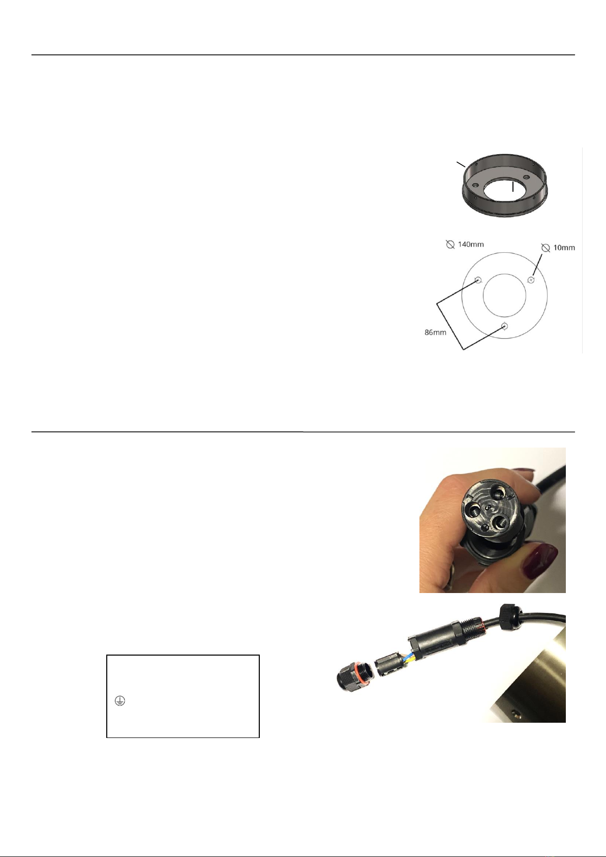
1. Remove 4 x socket screws at the foot of the bollard tube with a 2.5mm socket wrench
(supplied) and lift the bollard body from the mounting base.
2. Position bollard base in the desired location, ensuring the supply cable is central to the
base with plenty of slack for ease of wiring (approx. 300mm recommended) and the PIR
will be facing in the correct direction (in line with one of the 4 holes on the base).
3. Secure the base in place with the correct fixings for your surface (3 x heavy duty anchor
bolts have been supplied for optional use).
4. Lay the bollard on a soft covering, e.g. blanket, beside the base to expose the in line
connector and wire the bollard to the power supply as per below (see WIRING).
5. Reposition the tube back over the bollard base and secure in place with the 4x socket
screws removed in step ‘1’, ensuring the PIR sensor faces the correct direction.
6. Remove 4 x M4 socket screws from bollard head using a 2.5mm socket wrench (supplied).
7. Insert E27 light bulb (see LAMP INSTALLATION / REPLACEMENT below).
8. Carefully place the head over the bulb, being careful not to knock or damage the bulb, and
check that the holes are aligned with those at the top of the tube.
9. Replace head and secure in place with the screws removed in step ‘6’, ensuring the clear
rubber o-rings are still in position. Alternate the tightening of screws to prevent
misalignment.
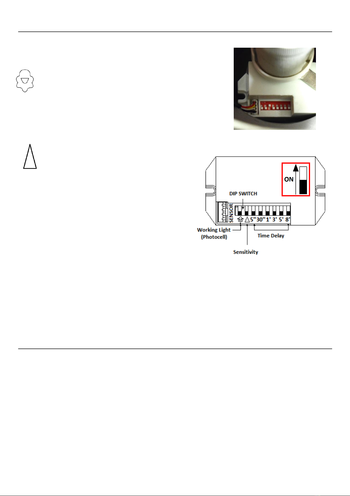
10. Test the bollard. If the photocell setting is set to “ON”, the sensor will need to be mostly
covered to enable daytime testing. Settings can be adjusted via the dipswitch (see PIR SETTINGS below).
IMPORTANT: Do not overtighten the surface mount base as this could lead to fracture. Do not use high power tools.
WIRING:
Always ensure the power supply is turned off prior to wiring
The in-line connector supplied can be used with 3 core cable up to 1.5mm² (10mm diameter). To
wire:
1. Unscrew and remove the male end cap & nut (anti-clockwise) completely to expose the
connector block.
2. Unscrew the female end cable at the cable end and pass over the cable slightly to allow
movement of the connector.
3. Push the cable further inside the in-line connection to fully reveal the connector block
4. Pass the mains power feed through the fully removed end cap and wire each inner cable
to the correct terminal, securing in place with the terminal screw. Ensure the screw
clamps the conductor, not the inner sheath, and that all cables are secure with no loose
conductor strands (see terminals info).
5. Push the connector block back inside the in-line connector casing fully, ensuring the red
rubber grommet has not dislodged at the male end of the casing,
and refasten the female end cap tightly.
6. Refasten the male end cap & nut fully to clamp the power cable.
Ensure the red o-ring is in place before fastening.
NOTE: At the male end cap, the nut fastens to the casing, the cap clamps around the cable. Ensure both are secure.
TERMINALS (labelled to left):
N = Neutral / Blue
L = Live In / Brown
= Earth / Yellow & Green
Colours of wire sleeving may vary
slightly –Test prior to use.
5mm
2mm

Full product range & more information: www.lumenalights.com
PIR SETTINGS:
Always ensure the power supply is turned off prior amending settings
The settings of the PIR Motion Sensor are adjustable via the dipswitch, located below the bulb
holder and accessible at the top of the tube by removing the head.
Photocell (dusk to dawn):
•When switched to OFF (down), the sensor will be triggered during day and night
(<2000 LUX approx.)
•When switched to ON (up), it will work only during darkness (<10 LUX approx.)
Sensitivity:
•When switched to OFF (down), low sensitivity is selected (up to
3m)
•When switched to ON (up), high sensitivity is selected (up to 6m)
Time-delay:
•5" = 5 seconds
•30" = 30 seconds
•1ˊ= 1 minute
•3ˊ= 3 minutes
•5ˊ= 5 minutes
•8ˊ= 8 minutes
TESTING:
1. Select 5" to ON position (up) ensuring all other switches retain their original OFF position (down)
2. Switch on power and wait for the load to turn on and off again. The sensor is now ready
3. Activate the sensor with movement to turn on the load. After 5 seconds it will turn off automatically
4. If the Photocell switch is set to the ON position, the sensor will not be triggered with movement during daylight
5. Cover the sensor with your hand and the load will turn on; remove the cover and after 5 seconds it will turn off automatically.
LAMP INSTALLATION / REPLACEMENT:
Always ensure the power supply is turned off prior to changing the lamp
1. Remove 4 x M4 socket screws from bollard head using a 2.5mm socket wrench (supplied).
2. Remove the head by lifting this off the bollard tube / body.
3. Insert lamp (screw base –E27). This fitting is recommended for use with an LED Corn Bulb (no extender required). An E27 bulb
holder extender has been supplied for use with standard GLS LED lamps. To remove a lamp, unscrew anti-clockwise.
4. Replace head and secure in place with the screws removed in step ‘1’, ensuring the clear rubber o-rings are still in position. Alternate
the tightening of screws to prevent misalignment.
NOTE: Always turn the lamp at the base, do not grip the glass / polycarbonate lens during removal / installation.
Table of contents
Other UMENA Lighting Equipment manuals