UMS 7-90 cc User manual
Gas Radial Engines
User Manual For
Technologies Limited
2
NOTICE
All instructions, warranties and other collateral documents are subject to change at the sole
discretion of UMS, Inc. For up-to-date product literature, and click on the support tab for
this product.
The following terms are used throughout the product literature to indicate various levels
of potential harm when operating this product:
NOTICE: Procedures, which if not properly followed, create a possibility of physical property
damage AND a little or no possibility of injury.
CAUTION: Procedures, which if not properly followed, create the probability of physical
property damage AND a possibility of serious injury.
WARNING: Procedures, which if not properly followed, create the probability of property
damage, collateral damage, serious injury or death OR create a high probability of
supercial injury.
Meaning of Special Language
This is a sophisticated hobby product and NOT a toy. It must be operated with caution and
common sense and requires some basic mechanical ability. Failure to operate this Product in a
safe and responsible manner could result in injury or damage to the product or other property.
This product is not intended for use by children without direct adult supervision. Do not attempt
disassembly, use with incompatible components or augment product in any way without the
approval of UMS, Inc. This manual contains instructions for safety, operation and maintenance.
It is essential to read and follow all the instructions and warnings in the manual, prior to assembly,
setup or use, in order to operate correctly and avoid damage or serious injury.
Age Recommendation:
Not for children under 14 years. This is not a toy.
CAUTION: This product can become extremely
hot when in use, which could lead
to burns.
WARNING: Read the ENTIRE instruction manual
to become familiar with the features
of the product before operating. Failure
to operate the product correctly can result
in damage to the product, personal
property and cause serious injury.

3
• Always ensure the aircraft is secure and will not move once the engine is started.
• Always rebind your transmitter to your receiver(s) after setup and before rst ight.
• Always ensure the throttle failsafe is set to low throttle in your transmitter.
• Always perform a range check prior to ight.
• Always cut off the fuel supply (pinch or disconnect the fuel line to the carburetor) or use
the throttle linkage to shut off the air in order to stop the engine.
• Never use hands, ngers, or any other body part to stop the propeller.
• Never throw any object into a propeller to stop it.
• Never run the engine in the vicinity of loose small objects, such as gravel or sand, to avoid
the propeller uncontrollably throwing such materials.
• Never wear loose clothing or a loose neckstrap when operating your model engine as these
items could become entangled in the propeller.
• Never have loose objects such as screwdrivers, pencils, etc. in your pockets when operating
your model engine. These could fall into the propeller.
• Never allow fuel to come into contact with eyes or mouth. Gasoline and other fuels used
in model engines are poisonous.
• Always ensure gasoline and fuel are stored in a clearly marked container away from
the reach of children.
Safety Warnings
Model engines produce a substantial amount of power, which can create unsafe situations if not
used correctly. Always use common sense and observe all safety precautions when operating,
handling or performing any procedure involving your engine. Failure to follow safety precautions
could result in serious injury and property damage.
• Always ensure spectators, especially children, are at least 30 feet away when running
the engine.
• Always ensure that the propeller is securely attached to the engine shaft and all retaining
fasteners are tightened properly before EACH ight. Use of blue threadlock to tighten nuts
is advisable.
• Always keep small parts out of the reach of children as they can be choking hazards.
• Always secure the airplane before powering the engine.
• Always keep your face and body away from the path of the propeller blades when starting
or running your engine.
• Always stand behind the propeller when making carburetor adjustments.
• Always wear safety glasses or goggles when starting and running your engine.
• Always keep your fuel in a safe place away from sparks, heat or anything that can ignite.

4
engine, one of the nest engines in the market
place today. UMS is committed to you
having a positive experience and a lifetime of great
operation with your new engine.
It is important that you read the engine manual
before starting the engine for the rst time.
UMS radial engines have different requirements
than engines that you may have operated
in the past. The manual provides important
information for installing the engine, selecting the
correct propeller, fuel requirements and proper
engine break-in procedures.
• Always use the correct size and pitch of propeller for your engine. Refer to the Propeller Chart
in this manual.
• Always conrm proper balance of your propeller prior to installation of the engine. Failure
to do so could result in damage to the engine and/or airframe.
• Always utilize an electric starter to start your engine.
• Always discard any propeller that is nicked, scratched, cracked or damaged in any way.
• Always run your model engine in a well-ventilated area. Model engines can produce possibly
harmful carbon monoxide fumes.
• Always store your fuel safely in a sealed, water-resistant container.
• Always store fuel in a cool, dry location. Do not allow fuel containers to come in direct
contact with concrete, as the fuel may absorb moisture.
• Always responsibly discard fuel if there is condensation and/or water inside the fuel
container.
• Never return unused fuel from the fuel tank back into the fuel container.
• Never attempt to repair or modify a propeller beyond its intended use.
• Never handle model engines, mufers and/or tuned pipes until they have had time to cool.
They can become extremely hot when in use.
Precautionary Guidelines
Always mount the engine securely on a bench mount or high-quality engine mount.
•
Introduction
Thank you for purchasing an UMS radial
5
Engine Specications
2-stroke oil • Engine bafes
• Propeller • Electronic ignition battery (2S 7.4V Li-Po or 6V Ni-MH)
• Fuel line (3.5mm ID) • Electronic ignition switch
•
•
Properly installing the engine to either the airframe or an engine test stand for break-in is crucial
to getting the most power and longest life from your engine.
WARNING:
Never use a standoff between the
rewall and the mounting ring. Vibration
between the standoff and the mounting ring
will damage the mounting ring and cause
the engine to separate from the airframe.
WARNING:Always attach the engine mounting
ring to a at plate surface, such as
6–8mm plywood or carbon ber plate.
Engine mounting screws
Installing the Engine in the Airframe
Needed to Complete
Engine 7-90 cc
Type
Displacement
Bore
Stroke
Cylinders
Total Weight
RPM Range
Fuel
Engine Dia & Length
Mufer Type
HP
Cylinder Type
Carb Type
Propellers Range
4 - Stroke Petrol
90.0 cc
25.0 mm
26.0 mm
3.5 Kg with
Ignition Coil
1200 - 6000
Petrol with 1:32
Two Stroke oil
23.0 cm & 20.0 cm
Collector Ring
WT 621
2-Blade:26x10, 24x12
6.0
ABC
7
6
2. Use three steel screws (not included) to
attach the engine mounting ring to the
rewall. The size of the mounting ring screws
will vary depending on the aircraft. Always use
the largest size screw that will t through the
mounting ring.
To keep the engine from coming loose in ight:
Firewall with blind nuts installed: Always
use split washers between the mounting
ring screws and the mounting ring.
Firewall with through bolts installed:
Always use nylon locking nuts with
bolts through the rewall.
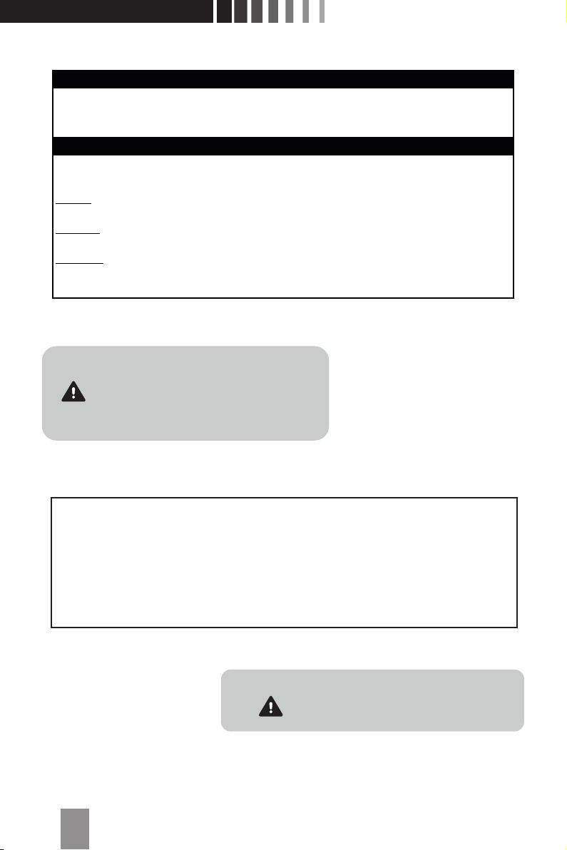
3. Make sure the fuel tank is no farther than 200mm (8 in) from the back of the rewall.
• Always use a fuel lter inside the fuel tank.
• W e recommend using large (2.5mm) inner diameter fuel line.
• M ake sure there are no sharp bends in the fuel line between the fuel tank and the engine.
4. Attach the throttle servo linkage to the throttle bellcrank on the engine.
5. Add your choice of activation mechanism (servo operated pushrod)
for the choke lever.
1. Install the engine on the airframe with Cylinder
#1 in the top (12:00) position (Cylinder #1
is above the UMS Engines logo).
Note : Install the tank on the centre line of the engine
Centre Line

7
a cooling airow exhaust:intake ratio of 3:1 to 5:1. A large open cowl may lead you to believe
there is adequate cooling; however, you must make sure air is owing through the cowl and
the cylinder head ns. Achieving the proper ratio typically requires cowl and/or engine
bafes to reduce the open intake area.
1. Ensure there is adequate cooling air moving through the cylinder head cooling ns.
The intake air tends to move through the path of least resistance (between the cylinders)
instead of through the cylinder cooling ns.
2. If necessary, add bafes to the engine to prevent air from moving between the cylinders.
Engine bafes force cool air through the cooling ns and greatly reduce the intake area
in the front of the cowl.
3. Add cooling bafes to the engine cowl between the top of the cylinder heads and the inside
of the cowl.
4. Do not cover the engine exhaust tube with the bafe. The exhaust tube requires direct
air cooling to prevent damage to the exhaust valve.
It is very important to consider adequate cooling inside the airplane cowl. Engines require
Engine Cooling Requirements
The electronic ignition requires a 6—7.4V 2500mAh battery. For the best performance,
we recommend a 7.4V 2S Li-Po battery (minimum 2500mAh) and a suitable switch (JRPA001).
A voltage regulator is not required for use with a 7.4V 2S Li-Po battery.
An electronic ignition is included with your engine. The spark plug wires are labeled for each
cylinder—ensure the spark plug wires are connected to the correct cylinders. Connecting the
spark plug wires to the incorrect cylinders will change the ring order and the engine will not
run correctly.
Installing the Electronic Ignition
unit. The ignition unit does not include reverse
polarity protection. Ignition unit damage
caused by reverse polarity is not covered
under warranty.
NOTICE: Always observe proper polarity when
connecting the ignition battery to the ignition

8
Specic fuel is required for the break-in process. Please refer to the chart above for the proper
fuel. Break-in fuel contains additional oil compared to fuel you will use for everyday ying. The
additional oil is critical for cooling and removing break-in debris from the engine.
Run the engine through four tanks of fuel (32 oz/1000mL) for 3—4 minutes at a time, allowing
the engine to cool between runs. Vary the throttle between idle and ¾ throttle for the rst 30
minutes of engine run time. Do not exceed ¾ throttle during the break-in. The engine break-in
process is complete after the rst four tanks of fuel and you can begin tuning the engine for
normal ying.
A good break-in process is essential to the longevity and performance of your UMS radial
engine. You can complete the break-in process by either mounting the engine on a test stand
or on an airframe. If you choose to mount the engine on an airframe, remove the cowl during
break-in to ensure adequate cooling.
Engine Break-In Process
Fuel Selection
Break-in Fuel Normal Flying Fuel
gasoline:2-stroke oil 32:1 40:1
Propeller Selection
Propeller selection is critical for proper engine operation. You can nd recommended propel-
lers and operating RPM ranges in the specication chart. UMS radial engines have a lower
operating RPM range and greater torque within that range that require more blade pitch and
increased in-air pitch speed for your airplane.
To increase climbing and acceleration: Increase propeller diameter and decrease blade pitch.
To increase top speed: Decrease propeller diameter and increase blade pitch.
Make sure the propeller is securely mounted to the crankshaft before attempting to start
the engine.
1. Remove the Allen bolt from the propeller washer.
2. Install the propeller on the crankshaft.
3. Secure the propeller with the six allen bolt

9
Engine Tuning
The break-in settings for the carburetor needles are:
High-speed needle: 2 turns open
Low-speed needle: 1 1/4 turns open
Use a tachometer to tune the engine based on RPM.
WARNING: Always adjust the carburetor
from behind the propeller. Keep all loose
items away from the propeller at all times.
Never reach over or around the propeller.
of each ying day.
1. Fill the fuel tank with fuel.
2. Make sure the fuel lines are properly connected to the carburetor.
3. Switch off ignition, turn the propeller with closed choke ap until the fuel reaches
the carburetor
4. Switch on ignition and holding the propeller rmly, turns the propeller 2-3 full times
to such fuel into the engine.
5. Now with rm ick, try and start the engine.
6. Engine run approx. at 1000 rpm for two minutes to warmup
Use a high quality gear oil to lubricate the outer parts of the valve train at the beginning
Starting the Engine
accumulate excess fuel or oil either in storage or during the priming process. Before
beginning the starting process be sure to:
1. Rotate the propeller by hand. During the rotation, if you encounter a point where there is
serious resistance to the rotation, STOP. This is an indication of a ooded cylinder and what
you are feeling is hydraulic lock. Any further attempts to force the rotation of the engine can
result in damage to the cylinder or conrod.
2. If you encountered hydraulic lock, remove the spark plug from the lower two cylinders
and the engine should rotate freely. Continue to rotate until all the excess uid has been
removed from the cylinder.
3. Reinstall the spark plug and continue with the starting process.
Because of the nature of radial engines, it is not uncommon for the lower cylinders to
Checking for a Flooded Cylinder

10
High-Speed Needle Tuning
Once the engine is running reliably at full (open) throttle:
1. Lean the high-speed needle 1/16 of a turn at a time.
2. Wait 2–3 seconds for the engine to respond.
Radial engines do not respond immediately
to tuning changes.
a. If there is an increase in RPM: Lean the
high-speed needle an additional 1/16 turn and
wait for the engine to respond to the tuning
change. If there is no increase in RPM
after the change, turn the high-speed needle
back to its previous position.
b. If there is a decrease in RPM: Richen
the high-speed needle 1/8 turn and wait for
the engine RPM to stabilize.
3. Repeat Step 2 until you determine the
maximum RPM with the fuel and propeller
you selected.
4. Richen the high-speed needle so when full throttle
is applied, the engine rpm will be steady
(not drop off) after reaching its peak RPM. Richening
the high-speed needle allows the RPM
to increase when the airplane is ying.
1. Start the engine.
2. Move the throttle stick up until the engine is running at approximately 2,000 rpm.
3. If you are using separate exhaust pipes, use a temperature gun to make sure hot exhaust
is exiting all engine cylinders. If you are using a collector ring, use a temperature gun to make
sure all the cylinder temperatures are similar and ring smoothly.
4. Move the throttle stick up to full (open) throttle. If the engine runs rough or if some cylinders
are not operating, the fuel mixture is too rich.
5. Lower the throttle stick until the engine reaches 2,000 rpm. Lean the high-speed needle
(turn clockwise) 1/16 turn.
6. Quickly raise the throttle stick to full (open) throttle. If the engine stops running,
the high-speed needle setting is too lean.
7. Lower the throttle stick until the engine reaches 2,000 rpm. Richen the high-speed
needle (turn counterclockwise) 1/8 turn.
8. Repeat Steps 4–7 until the engine is running reliably at full (open) throttle.
Table of contents
Other UMS Engine manuals


