CLASSFICATION.
Installation Manual
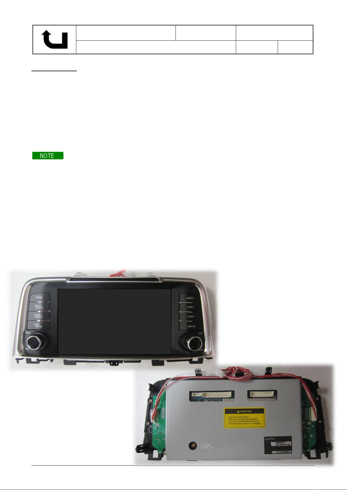
UNAVI F1 for Kia Optima UVO Installation Guide
Information & Manual Copyright © 2016 UNAVI USA, Inc. All rights reserved. Date: 5/3/2016
TPMS (TIRE PRESSURE MONITORING SYSTEM)
WARNING LAMP –ELECTROMAGNETIC INTERFERENCE
SYMPTOM/CONDITION
The TPMS malfunction indicator lamp may be illuminated if the vehicle is moving around electric power
supply cables or radio transmitters at police stations, government and public offices, broadcasting
stations, military installations, airports, transmitting towers, etc. External electronic devices connected
to the vehicle's power outlets (notebook computer, seat warmer, massager, coolers, GPS navigation,
mobile phone charger, etc.) may also cause this condition. The TPMS malfunction indicator lamp
generally turns off after the vehicle is removed from such interferences.
DIAGNOSIS:
If the TPMS indicator lamp is ON, and all four wheel sensors are checked and are working correctly,
external electronic devices connected to the vehicle's power outlets (notebook computer, seat warmer,
massager, coolers, etc.) may be the cause of this condition. Car manufacturers are aware that any
aftermarket device operating especially on the CAN-Bus system can trigger random warning lamps.
ACTION:
1. Please inspect if there are any other electronic devices inside the vehicle that may cause
electromagnetic interferences with the TPMS.
2. Drive the vehicle out of the strong electric field for about 5 minutes to verify that the condition is
corrected.
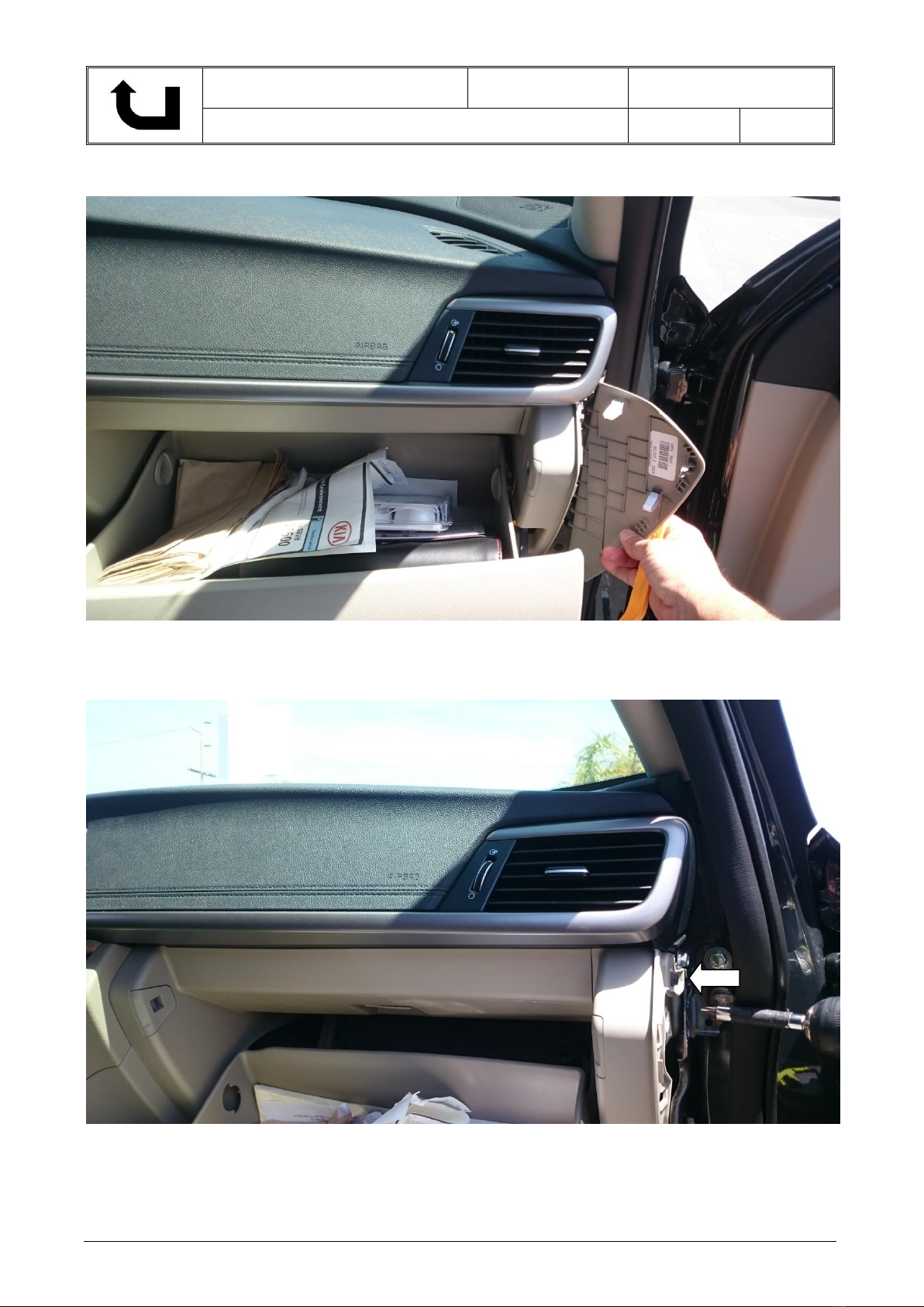
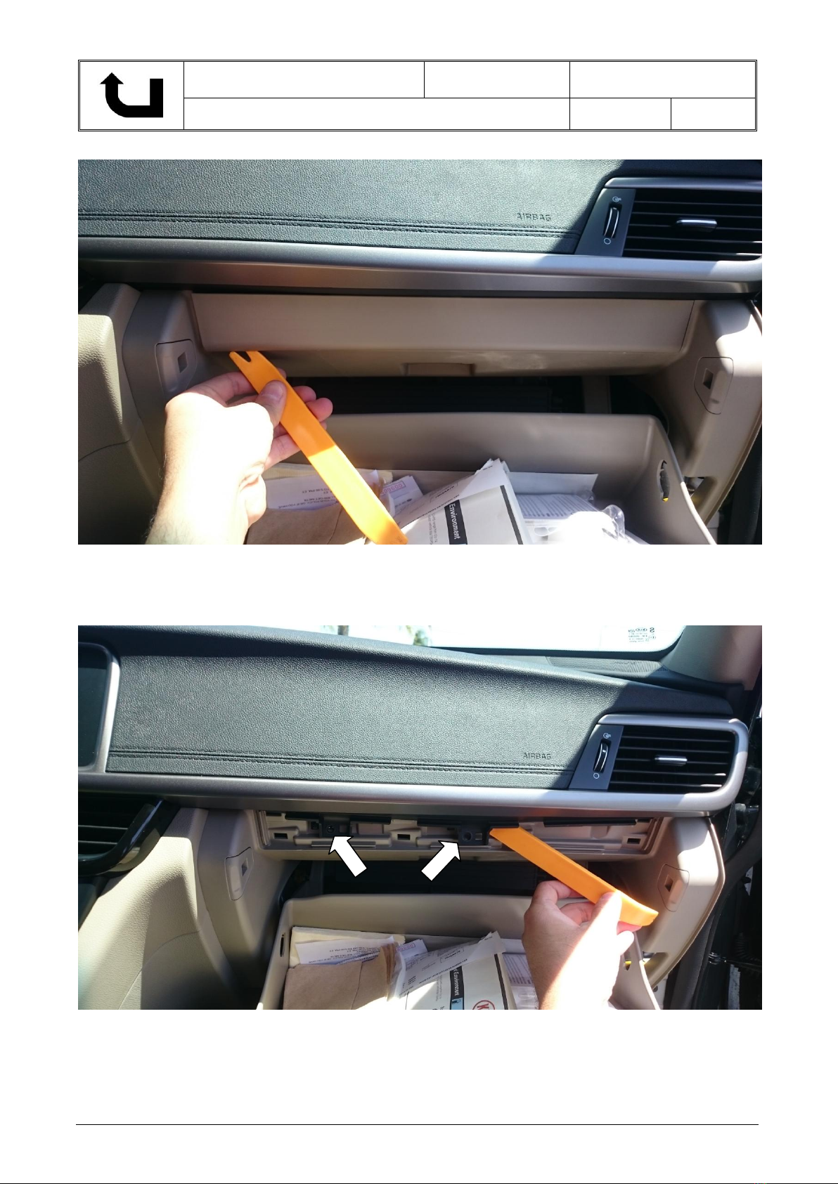
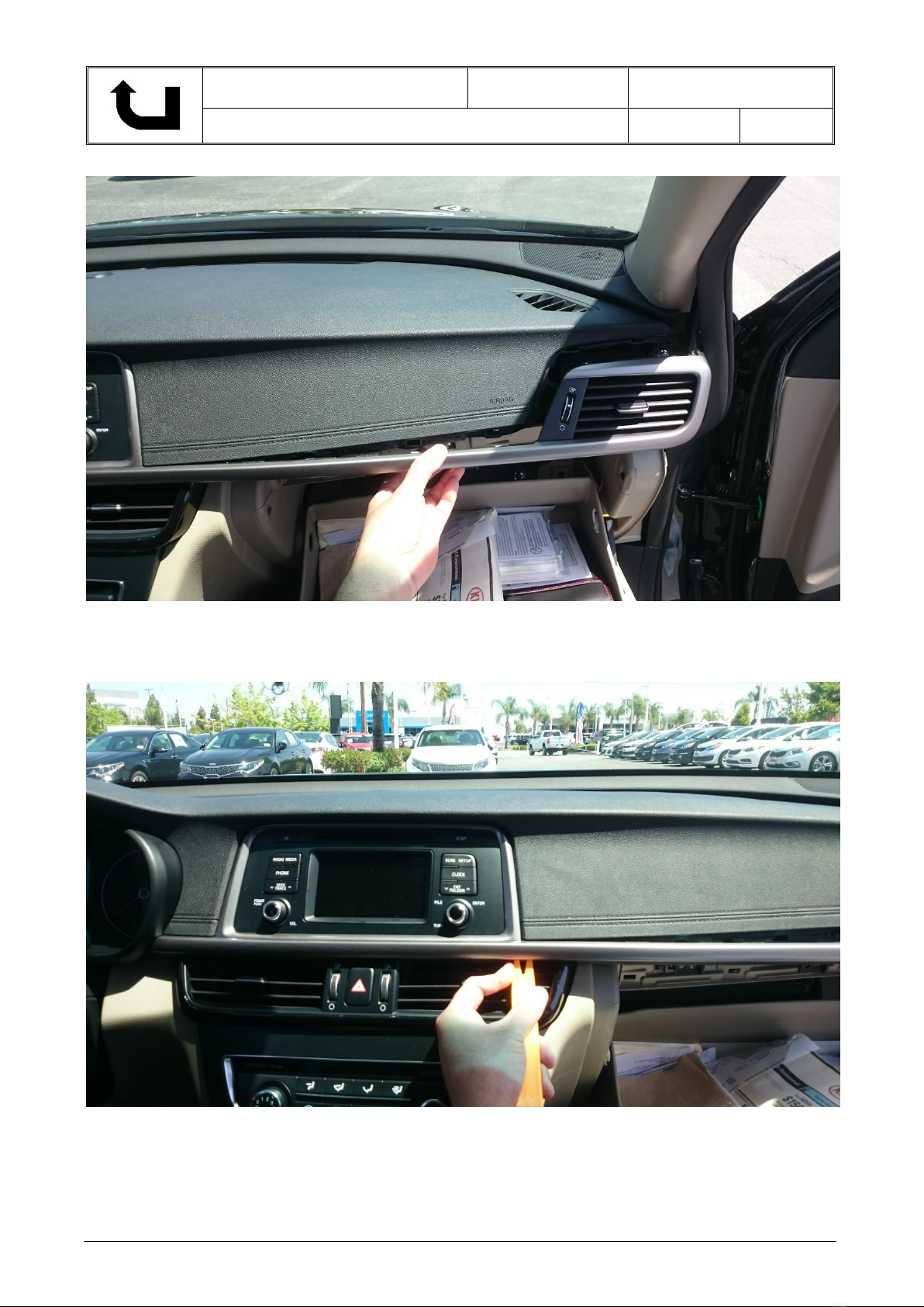
3. Relocate the Control Box and its related cables away from the TPMS sensor (typically located
behind the glove compartment).
4. If the above doesn’t work, use a metallic shield wrap or a similar material to wrap around the
Control Box and its cables with both ends of the shield connected to chassis ground at the point
of entry.
GPS ANTENNA INSTALLATION
The delay when the GPS receiver is first switched on is due to the latest ephemeris data being
downloaded, which is essential for the GPS receiver. The data is valid for around 4 hours and takes
approximately 20 seconds with a clear line of site to a satellite. It takes longer if using multiple satellites,
for instance if the GPS receiver is moving during first acquisition.
The antenna needs to be facing the sky through a non-metallic enclosure.Ametallic enclosure (including
window tints) will prevent the RF signal being received by the antenna and cause a Faraday cage effect.
Likewise, positioning the antenna near to obstructions such as laptop screen or where hands will be over
the antenna should also be avoided, as the shielded will have a negative performance.
The GPSAntenna base is magnetic. On metal vehicles, position the antenna in the center of the vehicle
at the highest point.
For vehicles with non-metallic mounting surfaces, a metal plate with adhesive strips has been included
in the kit for easy mounting and installation. It is STRONGLY recommended to use this metal plate
underneath the antenna as it will improve signal acquisition.
Once the antenna has been positioned, route the antenna cable carefully to avoid damage.
Position the GPS antenna in the center of the vehicle at the highest point with a clear view of the sky.