Underhill Novo User manual

© 2013 Underhill International Corporation
UNDERHILL INTERNATIONAL
20505 Crescent Bay Drive
Lake Forest, CA 92630 USA
tel: (949) 305-7050 •fax: (949) 305-7051
1-866-863-3744 •www.underhill.us
An industry leader in innovative watering
products all over the world, Underhill brings
33 years of know-how in developing our
inventory of “Products that work...smart.™
Form No. UNM-B13
Novo™
63-Station 2Wire Converter
Products that work...smart.™
OPERATION MANUAL
www.underhill.us • 1-866-863-3744


TABLE OF CONTENTS
Introduction 1
Product Benefits 1
System Overview 2
How does it Work? 2
Mounting and Installation 4
Installing the Novo 4
Wiring the Novo 4
Programming a Decoder 8
Wiring a Decoder to a Valve Solenoid 9
Programming an External Sender 9
Connecting Senders to a Host Controller 10
Key Functions 11
Dial Positions 12
Example Screens & Their Keys 13
View Sender Commands 15
View Decoder Setup 16
2Wire Communication Path & Maximum Wire Distances 18
Electrical Specifications 21
FCC Notice 22
Warranty 23
Index 25

1
INTRODUCTION
Congratulations on the purchase of Underhill International’s Novo™product
offering ease of installation and operation for large estate and light to medium
commercial irrigation applications.
Product Benets
The Novo™ is easy to install and operate offering a number of customer benefits
that also reduces field troubleshooting when needed.
Simple – Compact design for faster and easier mounting to an interior wall or
within a wall mount or pedestal-type enclosure for outdoor applications.
Flexible and Easy to Expand – The Novo is intended to operate up to 32
stations on a 2Wire system using any host conventional multi-wire irrigation
controller. See “System Overview” on next page.
An additional 31 stations in 8-station increments for a total of 63 stations
can also be managed by installing Underhill’s Universal Senders. See Product
Overview on the page 3.
Proven – Install with a high level of trust knowing that Underhill has more than
200,000 station decoders installed worldwide.
Will operate with poorly insulated wire when retrofitting a multi-wire system.
Uses pure AC power to the decoders so no electrolytic destruction of field
wiring occurs.
No additional grounding is required along the 2Wire path, except at the Novo.
No special shielded communication wire is needed for the 2-Wire path which
can simply be 12, 14, or 18 AWG irrigation wire commonly found at most
irrigation suppliers that can save costs compared to other 2Wire systems.
Reliable – Superior resiliency to lightning protection.
Integrated Solution – All of the components necessary to provide up to 32
stations in one package.

2
SYSTEM OVERVIEW
How does it Work?
The following two diagrams represent typical installations of the Novo™
depending on how many stations need to be managed. The Novo allows any
conventional, multi-wire, irrigation controller to manage a 2Wire system with
Underhill decoders. This is accomplished by mounting the Novo to a vertical
surface and connecting the included color-coded wire to a host controller’s station
outputs. The Novo in turn converts signals to the 2Wire communication path to
individual station valves with decoders.
The Novo is powered from an external AC adapter connected to a 120-volt or
220-volt power source. This is the same requirement whether the Novo is wall-
mounted indoors or outdoors in a weather-resistant pedestal-style enclosure.
Note: Underhill external transformers p/n’s TW-35VA-115V
or TW-35VA-220v are compatible with this product only.
Figure 2-1 depicts the Novo with a host controller managing up to 32-stations.
Assumes host controller can manage up to 32 stations.
MANAGING UP TO 32 STATIONS
Figure 2-1

3
Figure 3-1 depicts the Novo with a host controller managing up to 63 stations by
adding 8-station Senders for station counts above 32.
MANAGING UP TO 63 STATIONS
Figure 3-1
Note: Assumes the host controller must have sucient stations to manage
63 stations or if two stations are combined to a single decoder using a
controller with fewer stations.

4
MOUNTING AND INSTALLATION
Installing the Novo
The Novo installs to any vertical surface by using the upper 2 (qty) keyholes and
two lower holes (accessible inside the product) located on the back of the case.
See Figure 4-1.
MOUNTING KEYHOLES ON THE BACK CASE OF THE NOVO
Figure 4-1
Note: The Novo is not intended for outdoor applications without
protection from a weather-resistant enclosure. An outdoor
enclosure to accommodate the Novo and transformer can be
ordered separately p/n TW3-PLC.
1. Confirm the Novo is level horizontally. Locate and mark the center point
of the upper mounting holes. Drill 2 (qty) ¼” x ½”deep holes. Tighten the
fasteners so that approximately 1/8”of threads remain exposed. Hang the
Novo 2Wire Converter and confirm it is secure. Locate and drill the lower
mounting holes, then securing w/ 2 additional #6 fasteners.
Wiring the Novo
1. Opening the Case
Press the two left and right thumb tabs located on the underside of the
Novo case. The case will swing upward revealing several terminal blocks.
2. Connecting the Novo to a Host Controller
Locate the 9-conductor, multiple-colored wire that is included with the
Novo. Four (qty) x 36” lengths of wire are included providing connection
between a host controller and the Novo for up to 32 stations.
The 9th conductor is white and represents the valve common wire for that
specific terminal block only. All common wires need to be tied together as
shown in Figures 2-1 & 3-1.
Locate the four terminal blocks underneath the display cover of the Novo,
See Figures 5-1 and 5-2.
2 (qty) keyhole
upper mount
2 (qty) lower
mounting holes

5
Stations 9 - 16
Stations 25 - 32
Stations 17 - 24
Stations 1 - 8
NOVO FIELD WIRE TERMINAL BLOCKS
Figure 5-1
Common Wire
noted as “C”
Lowest station
number at
the bottom
VALVE STATION SEQUENCING
Figure 5-2
The Novo comes with four sets of color-coded, pre-installed cable assemblies
but if fewer stations are required, a cable assembly can be removed by pressing
down on the square button next to the terminal hole with a small flat-bladed
screwdriver and pulling on the individual wire at the same time.

6
Table 1 below provides the wire color-coding on each of the four terminal blocks
for the Novo. Confirm these wires are connected to a host controller’s station
outputs accordingly.
Table 1
NOVO STATION WIRE TERMINATIONS
Terminal Block Location Terminal Block Location
Lower Left Upper Left
Term
Blk
Sta
#
Sender
Wire Color
Term
Blk
Sta
#
Sender
Wire Color
JP8/9 Com White JP9/9 Com White
JP8/8 8 Violet JP9/8 16 Violet
JP8/7 7 Blue JP9/7 15 Blue
JP8/6 6 Green JP9/6 14 Green
JP8/5 5 Yellow JP9/5 13 Yellow
JP8/4 4 Orange JP9/4 12 Orange
JP8/3 3 Red JP9/3 11 Red
JP8/2 2 Brown JP9/2 10 Brown
JP8/1 1 Black JP9/1 9 Black
Terminal Block Location Terminal Block Location
Lower Right Upper Right
Term
Blk
Sta
#
Sender
Wire Color
Term
Blk
Sta
#
Sender
Wire Color
JP11/9 Com White JP12/9 Com White
JP11/8 24 Violet JP12/8 32 Violet
JP11/7 23 Blue JP12/7 31 Blue
JP11/6 22 Green JP12/6 30 Green
JP11/5 21 Yellow JP12/5 29 Yellow
JP11/4 20 Orange JP12/4 28 Orange
JP11/3 19 Red JP12/3 27 Red
JP11/2 18 Brown JP12/2 26 Brown
JP11/1 17 Black JP12/1 25 Black
Zip-tie the multi-conductor cable assemblies together. Strip back approximately
3/8-1/2” of wire insulation and terminate in the appropriate station outputs of the
host controller. Be certain to follow the same color-coding in the table above.
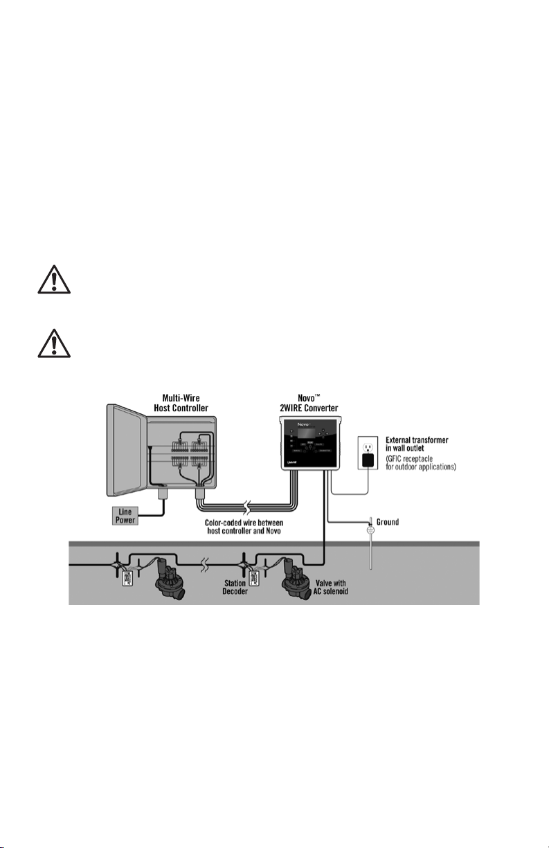
3. Connecting to the 2Wire Communication Path
Locate the three large, green-colored terminal blocks labeled L1, L2 and
“GND”. See Figure 6-1.
2WIRE INPUTS AND GROUND TERMINALS
Figure 6-1
Remove approximately 3/8” to ½”of wire insulation of the 2Wire communication
cable. Terminate a colored wire of the 2Wire path into the terminal labeled“L2”
and another colored wire into the terminal labeled “L1”.
4. Installing a Ground Wire (lightning protection) to a Ground Rod

7
Locate the“Gnd”terminal block shown in Figure 6-1. Insert a bare #14 copper
ground wire into this location. Connect the opposing end to a 5/8”diameter x 8’
long ground rod a minimum of 10 feet away from this location in accordance with
the American Society of Irrigation Consultants grounding specifications.
http://www.asic.org/uploads/assets/011007_121320_ASIC_GROUNDING_
GUIDELINES.doc
Note: Avoid sharp bends in the ground wire where a surge can jump to
other conductors when a surge occurs.
5. Connecting the Novo to an AC Power Source
Connect the Novo to a 120 or 230-volt, 50 or 60Hz power source using an
Underhill external transformer part number TW-35VA-115v or TW-35VA-230v
models.
Note: Make the wire connections to the Novo terminal block rst then plug
the opposing end of the transformer into the appropriate power source.
Locate the two small terminal block labeled as “AC” on the Novo terminal block
shown in Figure 7-1 below.
AC INPUTS
Figure 7-1
These are non-polarized terminals meaning either wire from the transformer can
be terminated in either one of the two terminals. Tighten with a small screwdriver.
Note there is a gray set of terminals for a future feature not oered in this
unit’s software version.
6. Adding more than 32 Stations
The Novo can manage up to 63 stations, given a host controller has this capability.
Note: The Sender(s) must be programmed prior to wiring into a host
controller.
To add more than 32 stations, install Underhill “Senders” p/n TW-SEN-8 in 8-station
increments (see Figure 8-1). Connect the thick red and black Sender wire to the
2Wire path (L1 & L2) as it exits the Novo (see Figure 3-1).

8
8STATION SENDER
Figure 8-1
PROGRAMMING A DECODER
An Underhill Decoder p/n TW-TK-DEC-1 is connected to each valve solenoid to be
operated from the Novo and a host controller. Each decoder must be programmed
using the Underhill Portable Programmer p/n DEC-PROG-115 or DEC-PROG-230
with the corresponding valve station number. See Figure 8-2.
PORTABLE PROGRAMMER FOR DECODERS
Figure 8-2
To program a Decoder complete the following steps;
1. Plug the red and black wires of the Decoder into the Programmer’s red and
black push terminals.
2. Plug the two yellow wires of the Decoder into the Programmer’s yellow
terminals. These are non-polarized so it makes no difference which yellow
wire is connected to a yellow terminal.
3. Set the decoders station number by pressing one of the gray “Raise or
Lower” buttons.
4. Press the red “Program” button to enter the station number.
5. Press the Green “Test” button to confirm the entered value has been saved.
If saved the green“Pass” LED will illuminate and the Decoder’s programmed
number will display on the LED’s. If the red “Fail” LED illuminates re-try
programming the decoder with the same or a different station number. Be
sure to retest before disconnecting from the Programmer.
6. Write the programmed Decoder number with an indelible pen in the little
white box on its label.

9
WIRING A DECODER TO A VALVE SOLENOID
Once all decoders are programmed and labeled, they can be wired to
corresponding valves in the field. The two yellow wires are connected the
valve solenoid wires (see Figure 9-1). The red wire lead should be connected to
the 2Wire path or L1. The black wire lead should be connected to a black wire
representing the 2Wire path or L2. Your 2Wire communication wire color may
vary.
DECODER WIRED TO A VALVE SOLENOID
Figure 9-1
PROGRAMMING AN EXTERNAL SENDER
For applications above 32 stations, Underhill 8-station External Sender’s p/n TW-SEN-8 can
be used up to manage up to 63 stations. These are programmed using the same portable
programmer. The Sender addresses must be programmed from 5-8. For example, stations
33-40 is activated with the Sender address 5, while stations 41-48 addressed as 6.
The following are steps to program a Sender. See Figure 9-2 shows a Sender connected to a
Portable Programmer.
1. Plug the red and black wires of the Sender into the programmer’s red and black push
terminals.
2. To set the Sender’s address on the programmer’s LEDS (value 5-8) by using the “Raise
or Lower” buttons, then press the red“Prog.” button.
3. The programmer will display CH0, CH1, CH2, CH3, then SN1, SN2... until it finds
the Sender’s existing number, then will program the new number into it.
If successful, the Green pass LED will come on and the Sender’s new number will
display on the LED’s. Immediately after programming, the LED in the bottom
of the Sender will flash the same number of times as the address programmed.
4. Write the Sender base address with an indelible pen in the little white box
on its label.
PROGRAMMING A UNIVERSAL SENDER
Figure 9-2

10
CONNECTING SENDERS TO A HOST CONTROLLER
Connect the small, color-coded wires from the Sender to the host controller’s
station outputs starting with station 33. Table 2 below identifies the wire color-
coding for Senders above 33-63.
Table 2
UNIVERSAL SENDER WIRE COLOR CODE
Universal Sender #5 Universal Sender #6 Universal Sender #7 Universal Sender #8
Sta
#
Sender
Wire Color
Sta
#
Sender
Wire Color
Sta
#
Sender
Wire Color
Sta
#
Sender
Wire Color
33 Black 41 Black 49 Black 57 Black
34 Brown 42 Brown 50 Brown 58 Brown
35 Red 43 Red 51 Red 59 Red
36 Orange 44 Orange 52 Orange 60 Orange
37 Yellow 45 Yellow 53 Yellow 61 Yellow
38 Green 46 Green 54 Green 62 Green
39 Blue 47 Blue 55 Blue 63 Blue
40 Grey 48 Grey 56 Grey X Grey
Com White Com White Com White Com White

11
KEY FUNCTIONS
The Novo offers several key functions for periodic maintenance or fast and easy
troubleshooting.
Saves a change that has been edited
Moves to a highlighted menu
Returns to the top of the menu
Undoes a change made to a value
Returns from a submenu to the previous menu
Undoes any changes edited
The “left and right” arrow buttons move a highlighted value
from left to right or increases or decreases a station number
The “+” or “-“ buttons increases or decreases a highlighted
value.
In manual mode, turns a station “On”(+) or “Off” (-)
Increases or decreases a station’s runtime in minutes or
seconds

12
DIAL POSITIONS
The Novo has five main menus that can be selected similar to a rotary dial by
simply pressing the corresponding menu button. When a button is pressed, a
small red LED will illuminate providing confirmation of the selected menu.
This is the primary position when operating
decoders from a host controller. The screen will
display any station(s) currently operating and
the total current draw of all stations operating
in milliamps (mA).
Note: Many host irrigation controllers only operate 2 stations at one time.
Note: The Novo cannot operate stations automatically from the host
controller and a station manually at the same time.
This menu is commonly used when the
system is shut-off typically associated with
“winterization” or if repairing or extending the
2Wire path. In this mode scheduled irrigation
commands from the host controller will not
operate and AC power to the 2Wire path
is de-energized.
Faults identifies when a station is not working.
The problem may be the
2Wire path,
A decoder,
A station solenoid.
The Diagnoscs menu provides two separate
funcons:
Determines if a command is received
between the Novo and a host controller.
Allows a user to reset decoder threshold
settings. See the Troubleshooting section
for more details.

13
The Manual menu allows the Novo to operate
any station independently
from a host controller.
EXAMPLE SCREENS & THEIR KEYS
The Novo uses buttons to select menus.
The RUN menu will display any one of the
following 3 display screens depending on
the task currently being executed:
1. Pressing the RUN button puts the Novo into
“automatic mode”to accept commands from a
host controller. When in RUN mode, the 2Wire
path is energized. See Figure 13-1.
This example will be displayed when a station or stations
are operating from a host controller during scheduled
irrigation, see Figure 13-2.
Figure 13-1 shows when the Novo is
connected to a host controller when
irrigation is not operating.
Figure 13-2 shows stations 2 and
12 are operating. The current draw
on the 2Wire path is approximately
462mA (0.462A), which is the sum
of all:
• Decoders (3mA per decoder)
• Any external Senders (3mA per
Sender) and,
• The current taken by the 2
operating valve solenoids (in this
example 228mA per solenoid).

14
This screen will be displayed when a decoder does not
respond to a host controller command and “FAULTS”
appears, see Figure 14-1.
1. Pressing the FAULTS menu button will display
faulty station(s) and whether it failed to turn “On”
or failed to turn “Off”.
2. Pressing the RUN button will return to the above
RUN screen, with the“Fault” message removed
automatically.
Note: When in the RUN mode, there may be a
8-10 second delay from the time the command is
entered in the host controller before a station will
operate. When operating a station from the Novo
in MANUAL mode, the delay is 1-2 seconds.
Pressing the FAULTS button will
display stations that have failed
to turn “On”, for a maximum of 7
stations per display screen. See
Figure 14-2.
1. Pressing the “Down”(-) button will display the
next 7 stations up to the total number of station
wired into the host controller.
2. Pressing the “Up” (+) button will scroll back up
to the previous 7 stations.
Note: The Novo does not display the time or date of
when a failure occurs.
Pressing the “NEXT/OK” button will navigate back
to the top of the“Faults”list.
If a station fails in (RUN) or (MANUAL) modes it will
be displayed in the FAULTS menu.
Figure 14-1 indicates a “Fault” that
can be any one of the following
issues:
• A field wiring issue between the
host controller and Novo terminal
blocks,
• A decoder that is not programmed
correctly,
• A break in the 2Wire
communication. path.
Figure 14-2 Indicates:
• Stations 1, 2, 3, 4, 5, 6 and 7 have
failed to turn off, (if a station fails
but sequentially starts working
again, it will be excluded from
this list).

15
The DIAGNOSTICS menu can perform two separate
functions;
Confirms if commands between the Novo
and a host controller are being received.
Provides a method to change the factory
default threshold values of decoders under
certain field conditions.
1. Press the DIAGNOSTICS button to display
the following screen see Figure 15-1.
2. Press the NEXT/OK button to “View Sender
Commands” shown in Figure 15-2.
VIEW SENDER COMMANDS
In this display the Novo verifies there is a wired
connection to the host controller.
1. Pressing the NEXT / OK button will show
the following in Figure 15-3.
2. Pressing the Down “-“ button will select
the lower submenu.
Note: Any row displayed with a “+” is “On”
even if the decoder has failed to operate.
This is useful in determining whether a
non-operating station is actually receiving
information from the host controller
(through the Novo or an external Sender(s).
3. When the host controller turns on a station,
the corresponding station position will be
displayed as an “+” symbol.
4. Other stations not turned “On”will be
displayed as a“-“.
Note: Station 64, although displayed is not usable
and will always be a “.” Or “-“ even if Sender #8 is
connected to a host controller.
5. If a station is displaying a“+” symbol and the
corresponding decoder has not come on,
then refer to the Troubleshooting Section.
If a “–“ or “.” is displayed, then it is not being
asked to turn “On”. Verify the Novo station
wiring or Sender (if installed) wiring on
the host controller. A row of “.” indicates the
Sender is not connected to the 2Wire path or is
programmed incorrectly or is faulty.
Figure 15-1 shows the top level of the
Diagnostics Menu. Pressing the “Next
/ OK” button will display the screen
below.
Figure 15-2 displays two Diagnostic
menus. Pressing the “Next / Ok”
button will display the “View Sender
Commands” screen while pressing
the “-“ button will select the lower
menu, “Edit Decoder Setup”
Figure 15-3 displays stations 1-32 are
available and stations 33-64 do not
have Senders currently connected

16
VIEW DECODER SETUP
To select the “View Decoder Setup”menu, press the
Down “-“ button to highlight the title, then press the
NEXT/OK button to view additional information in this
submenu. See Figure 16-1.
1. This function allows the user to alter default decoder
thresholds only when the Novo fails to keep a station
running during a scheduled start time or manual
operation. The high and low decoder threshold
settings can be changed if very low holding current
valves are in use or if two stations are tied to a single
decoder.
2. This operation is a value-added feature of the Novo
to accommodate rare field conditions. See Figure
16-2.
The MANUAL menu can be used for testing and
troubleshooting to isolate a field issue independent
of a host controller allowing a single station
to be operated at one time.
1. The default runtime is 2 minutes but additional
time can be added by pressing the“More”
button up to 9 hours. See Figure 16-3.
Figure 16-1 Press the “-“ button to
select “Edit Decoder Setup”, then press
the “Next / OK” button to move to the
next screen.
Figure 16-2 shows the factory default
settings for decoder thresholds for
“Low, High and Dwell” time values.
See the “Troubleshooting” section for
more details.
Figure 16-3 shows station 01 running
for 2 minutes.

17
Pressing the OFF button,
immediately stops any currently
operating irrigation and turns
off power to the 2Wire path to
decoders.
The Novo is turned off until the
“Run” menu is selected.
See Figure 19-1.
ADVANCED FEATURES
The Novo can be used with PLC or SCADA-type host products that can monitor
and alert when a decoder fails to turn “on”or “off.” There are 3 relay terminals,
Normally Open (NO), Common (COM) and Normally Closed (NC) available,
see Figure 17-2 to locate these terminals. This requires a hardwire path between
the Novo and a PLC or SCADA product for this advanced feature to operate.
When connected to a PLC or SCADA product and a faulty station is being
operated, the NO and COM are connected.
ADVANCED NO / NC INPUTS
Figure 17-2
Note: When entering this menu, automatic operation from the host
controller is suspended.
2. To advance to the desired station press the RIGHT or LEFT buttons.
3. When a station is running, the screen display will change from “READY” to
“RUNNING”, with the station number and time left displayed underneath the
station currently selected.
4. To turn the station “On”, press the Up “+” green button. The station run time is
shown next to ‘RUNNING’, shown as h:mm:ss and displays remaining time once
the station is started.
5. To turn the station “Off,”press the green button Down “-“ button
6. To select the next desired station, press the RIGHT or the LEFT buttons.
7. The default runtime is 2 minutes. To select a shorter runtime press, the “Less”
button to the left of the Manual menu button.
Note: Approximately1-2 seconds will elapse before the next station
turns on.
Table of contents
Other Underhill Media Converter manuals