Unic Stella di Caffe Specification sheet

NZ9009 02/15

2
1. SAFETY INSTRUCTIONS .....................................................................................................................................5
2. IMPORTANT INFORMATION .............................................................................................................................5
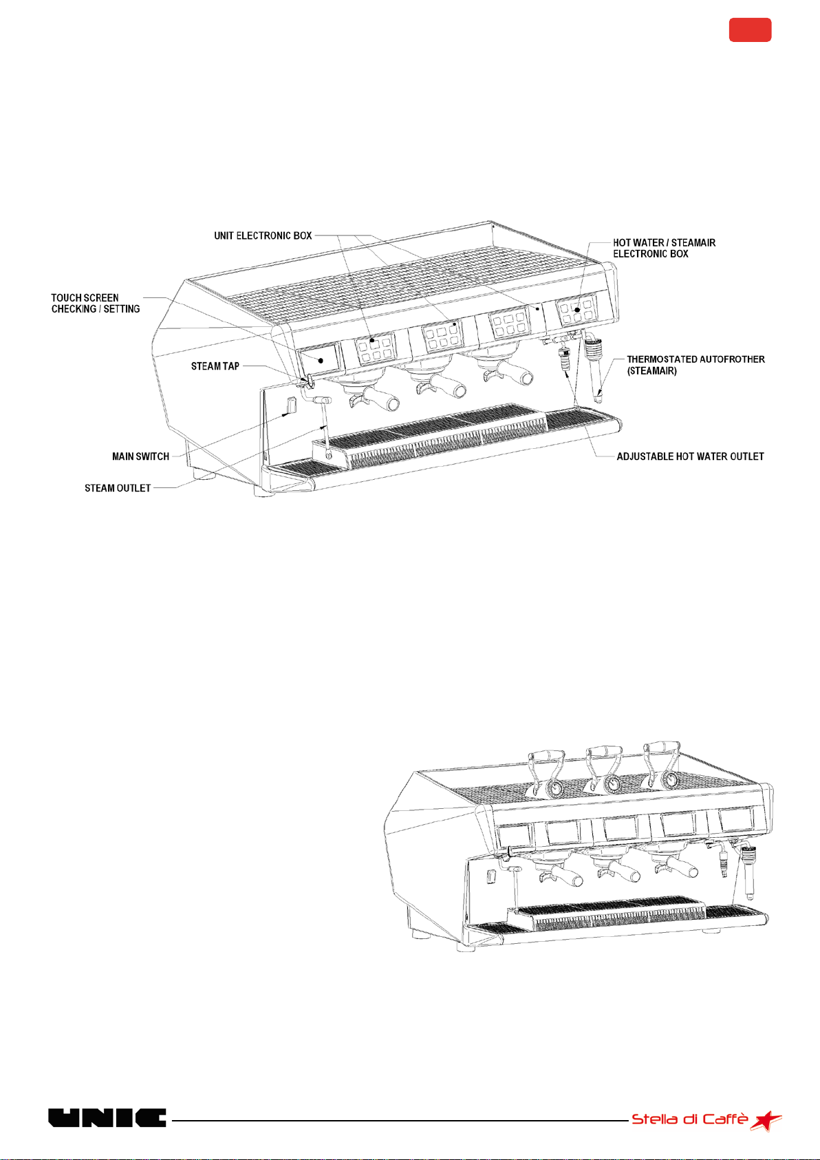
3. PRESENTATION OF THE STELLA DI CAFFE ..........................................................................................................6
STEAM
AIR
OPTION ................................................................................................................................................... 6
DUAL CONTROL OPTION (DCL)..................................................................................................................................... 6
4. FEATURES OF THE STELLA DI CAFFE ..................................................................................................................7
Unpacking the machine...................................................................................................................................... 7
Preparation of the location and installation of the machine ............................................................................. 7
5. COMMISSIONING .............................................................................................................................................7
WATER CONNECTION .................................................................................................................................................. 7
Water supply ...................................................................................................................................................... 7
Draining .............................................................................................................................................................. 8
ELECTRICAL CONNECTION ............................................................................................................................................. 8
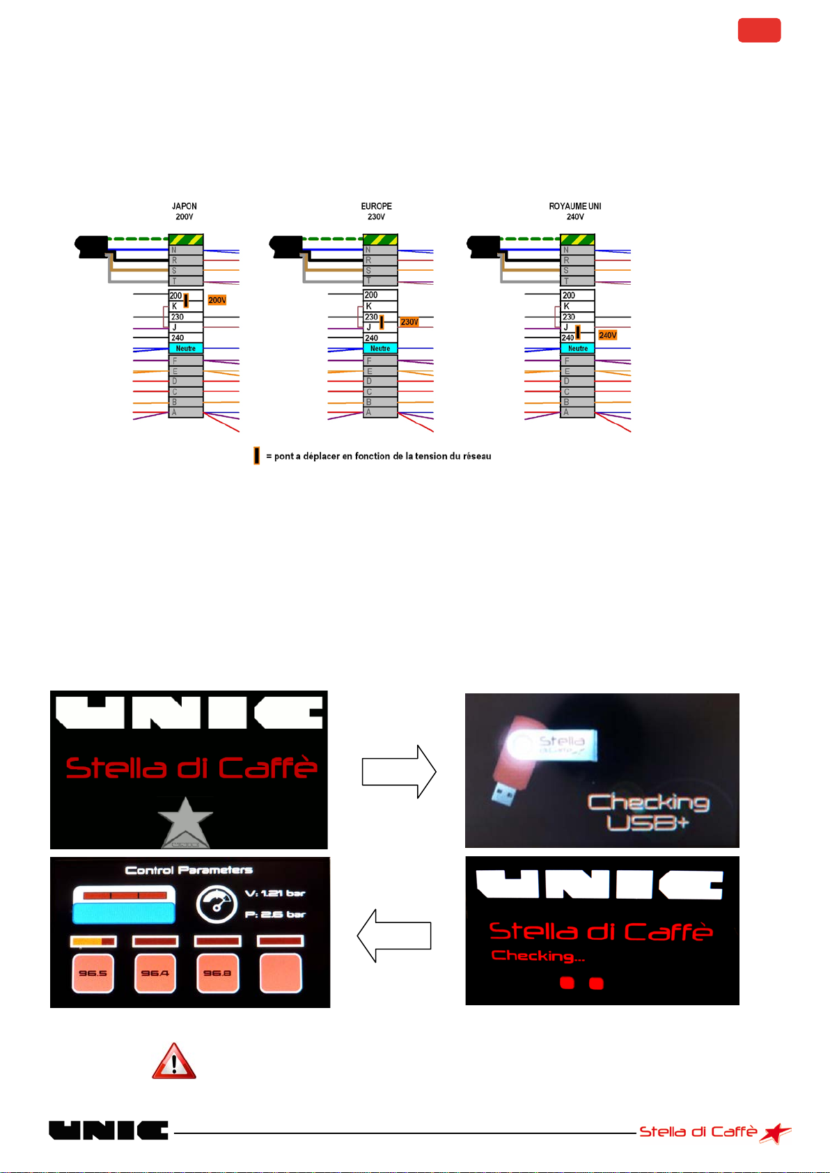
CHECK THE TOROIDAL TRANSFORMER IN RELATION TO THE MAINS VOLTAGE.......................................................................... 9
SWITCHING ON........................................................................................................................................................... 9
FILLING THE BOILERS.................................................................................................................................................. 10
Steam boiler...................................................................................................................................................... 10
Group boilers .................................................................................................................................................... 10
SWITCHING ON THE HEATING ...................................................................................................................................... 10
WHEN THE MACHINE IS WARMED UP ........................................................................................................................... 10
INSPECTION AND ADJUSTMENT ................................................................................................................................... 11
Adjusting the temperature ............................................................................................................................... 11
Adjusting the high pressure valve..................................................................................................................... 11
Adjusting the pump pressure............................................................................................................................ 12
Adjusting the water inlet solenoid valve .......................................................................................................... 12
6. INTERFACE .....................................................................................................................................................13
MENU DESCRIPTION .................................................................................................................................................. 13
BROWSING THE MENU ............................................................................................................................................... 14
SPECIAL MENU FUNCTIONS......................................................................................................................................... 14
7. PROGRAMMING.............................................................................................................................................15
CODES (LEVELS 1, 2AND 3)........................................................................................................................................ 15
To enable a level ............................................................................................................................................... 15
Change the password (level 1, 2 and 3)............................................................................................................ 15
SETTINGS................................................................................................................................................................. 16
Date & Time (levels 1, 2 and 3)......................................................................................................................... 16
Language (levels 1, 2 and 3) ............................................................................................................................. 16
Sound (levels 1, 2 and 3) ................................................................................................................................... 17
Wallpaper (levels 1, 2 and 3) ............................................................................................................................ 17
Light bar backlighting and keyboards (levels 1, 2 and 3) ................................................................................. 18
MACHINE ADJUSTMENT (LEVEL 1, 2AND 3) .................................................................................................................. 19
GROUP ADJUSTMENT (LEVEL 1, 2AND 3)...................................................................................................................... 19
Temperature adjustment (level 1, 2 and 3) ...................................................................................................... 20
Dose adjustment (levels 1, 2 and 3).................................................................................................................. 20
Pre-infusion adjustment (levels 1, 2 and 3) ...................................................................................................... 21
Self time adjustment (levels 1, 2 and 3)............................................................................................................ 23
STEAM ADJUSTMENT (LEVEL 1, 2AND 3) ...................................................................................................................... 23
STEAM
AIR
&HOT WATER ADJUSTMENT (LEVELS 1, 2AND 3)......................................................................................... 24
MISCELLANEOUS (LEVELS 1, 2AND 3) .......................................................................................................................... 25
Continuous/stop cycle key ................................................................................................................................ 26
Counter ............................................................................................................................................................. 28

3
8. USE ................................................................................................................................................................32
DOSAMAT CONTROL BOX (PART NUMBER 45100).......................................................................................................... 32
2-CUP CONTROL BOX (4-DOSE PART NUMBER:45102)................................................................................................... 32
3-CUP CONTROL BOX (6-DOSE PART NUMBER:45103)................................................................................................... 33
MANUAL CONTROL BOX (ON/OFF PART NUMBER:45101) ............................................................................................ 34
STEAM
AIR
CONTROL BOX (PART NUMBER 45104)....................................................................................................... 34
HOT WATER/MANUAL TAP CONTROL BOX (PART NO 45105) ........................................................................................... 35
STEAM
AIR
OPTION................................................................................................................................................. 35
DUAL CONTROL OPTION (DCL)................................................................................................................................... 36
9. CLEANING AND MAINTENANCE ......................................................................................................................37
AFTER EVERY USE ...................................................................................................................................................... 37
DAILY ..................................................................................................................................................................... 37
Semi-automatic cleaning .................................................................................................................................. 37
Semi-automatic rinsing..................................................................................................................................... 39
WEEKLY .................................................................................................................................................................. 41
FRONT PANEL CLEANING ............................................................................................................................................ 41
CLEANING THE STEAM
AIR
OUTLET ............................................................................................................................ 42
OTHERS .................................................................................................................................................................. 42
10. MAINTENANCE AND REPAIRS .........................................................................................................................43
CALIBRATION PROCEDURE OF BTA............................................................................................................................... 43
UPDATE PROCEDURES................................................................................................................................................ 44
BTA update ....................................................................................................................................................... 44
CPU update ....................................................................................................................................................... 44
BGX/BST UPDATE.................................................................................................................................................... 45
ASSIGNMENT OF ONE OR MORE BGX/BST CONTROL BOXES............................................................................................. 46
USING CIM-CREATOR................................................................................................................................................ 47
DIAGRAMS .............................................................................................................................................................. 49
BGX control box connections ............................................................................................................................ 49
BTA & BST control box connections .................................................................................................................. 50
CPU board connections..................................................................................................................................... 51
Lights and straps............................................................................................................................................... 52
Hydraulic diagram ............................................................................................................................................ 54
Fuses ................................................................................................................................................................. 56
Wiring diagrams ............................................................................................................................................... 57
FITTING /REPLACEMENT PROCEDURES ......................................................................................................................... 60
Mother board replacement (CPU) .................................................................................................................... 60
BTA/BGX/BST control box replacement............................................................................................................ 61
Fitting the long feet .......................................................................................................................................... 63
Rear feet (all versions) ............................................................................................................................................. 63
Front feet (standard version) ................................................................................................................................... 63
Front feet (V+ version) ............................................................................................................................................. 64
Removal / replacement of the steam tap cartridge ......................................................................................... 64
TROUBLESHOOTING .................................................................................................................................................. 65
List of fault codes for the technician................................................................................................................. 65
Troubleshooting................................................................................................................................................ 71
Replacing a faulty control box:......................................................................................................................... 71
Replacing the BTA control box ................................................................................................................................. 71
Replacing the BGX /BST control box ........................................................................................................................ 71
Individual test procedure for internal components .......................................................................................... 72
COOLING................................................................................................................................................................. 76
COMPUTER SYSTEM .................................................................................................................................................. 76
Debit – Credit system........................................................................................................................................ 81
Credit – Debit system and RS232...................................................................................................................... 82
SYSTEM INFORMATION .............................................................................................................................................. 83

4
11. STELLA PROGRAMME FLOWCHART ................................................................................................................84
LEVEL 0: USER.......................................................................................................................................................... 84
LEVEL 1: COFFEE SPECIALIST ....................................................................................................................................... 85
LEVEL 2: BARISTA ..................................................................................................................................................... 86
LEVEL 3: MANAGER /BOSS ........................................................................................................................................ 87
LEVEL 4: TECHNICIAN ................................................................................................................................................ 88
12. APPENDICES ...................................................................................................................................................89

5
1. SAFETY INSTRUCTIONS
- This machine is not intended to be used by persons (including children) with diminished physical, mental
or sensorial capacities, or lacking in experience and savoir faire, unless they are supervised or have
received training in the use of the machine from a person responsible for their safety.
- Children should be supervised to ensure that they do not play with the machine.
- This machine must only be used for its specific intended use.
- The manufacturer accepts no responsibility for damage caused by abnormal or incorrect use.
- Access to the service area is limited to persons having the necessary health and safety expertise and
practical experience of the machine.
- Before connecting or disconnecting the supply cable set the main switch to the 0 position.
- If the supply cable is damaged it should be replaced by the manufacturer, his repairer or a similar qualified
person to avoid danger.
- For electrical safety make sure that the machine is properly earthed.
- The manufacturer accepts no responsibility for damage caused by faulty grounding connections.
- Only qualified technicians are authorised to access the internal parts of the machine for maintenance or
repair.
- Use caution around hot surfaces such as the cup warmer, the group heads and the hot water and steam
outlets.
- Keep well clear of hot water or steam jets.
2. IMPORTANT INFORMATION
This machine must be:
- Placed on a stable horizontal surface
- Used at an ambient temperature between 5°C and 35°C (41°F – 95°F).
- Installed in compliance with any applicable local and national regulations.
- Connected to a water supply at a pressure between 1 and 8 bars
(0.1 to 0.8 Mega Pascal)
Before connecting the electricity supply, check that the mains supply complies with the specifications on the
manufacturer's plate on the machine.
For more details on the installation, adjustment or connections refer to the installation instructions or the
technical manual.
This machine should not be exposed to water jets or splashes.
Take care not to obstruct the machine air inlets with cloths or other objects.
If the machine is stored at an ambient temperature below 5°C (41°F) the hydraulic circuit (boiler and
pipework) must be drained.

6
3. PRESENTATION OF THE STELLA DI CAFFE
The Stella di Caffe has the advantage of having an independent boiler for each group, in addition to a large
capacity steam boiler. All the machine operating settings can be viewed and adjusted simply and intuitively
from the touch screen.
Steam
Air
Option
The Steam
Air
option is particularly useful for making cappuccino, it serves to convert the milk into foam in
a simple automatic operation: the injection of a mixture of air and steam (adjustable) heats the milk to a
programmed temperature (60° to 70°) and at the same time turns it into foam.
The machine stops automatically when the milk reaches this temperature, so preventing it boiling
Dual Control Option (DCL)
The dual control system makes it possible to
manually control the infusion and pre-infusion.
The automatic group control boxes remain fully
functional when the DCL option is installed.

7
4. FEATURES OF THE STELLA DI CAFFE
The machine is delivered in a cardboard packing case and screwed to a wooden pallet.
Unpacking the machine
Cut the bands
Open the box and take out the box holding the accessories
Separate the cardboard packing case from the pallet
Unscrew the nuts holding the machine to the pallet while tilting the control box slightly
Remove the machine from the pallet and place it on wooden blocks
Remove the screws and washers used for the transport
Preparation of the location and installation of the machine
Position the machine in its final location and level it with rubber washers if necessary
It is essential to leave a free space of 5 cm behind the machine if it is against a wall
Take care never to obstruct the air intakes on the top of the machine
The machine requires an earthed electricity wall socket corresponding to the specifications on the machine,
a water supply and a "waste water" drain with trap.
5. COMMISSIONING
Water connection
Fit a filter upstream of the machine - Check the hardness of the water: 5° to 10° KH recommended – If
necessary use a water softener.
Water supply
- Pressure: 0 - 10 bars
- Connection: 3/8" female gas thread (male connection on the machine) - Supplied with the machine
- Pipe: minimum inside diameter 8 mm
- Install a stop tap on the supply
To connect the water it is necessary to remove the right side panel from the machine:
Unscrew the fixing screws next to the cup warmer and pull the side panel towards the back
Screw the elbow end (3/8') of the braided flexible pipe to the brass connection on the right of the machine,
and the straight end (1/2') to the water mains connection or the water softener outlet (if used)
If a water softener is used, wash it out before using it.
Check for leaks
Refit the side panel on the machine

8
Draining
- Pipe with a minimum inside diameter 15 mm: supplied with the machine
To connect the drain pipe to the machine, it is necessary to remove the overflow tray (remove the overflow
tray grids, unscrew the 2 knurled screws and pull the overflow tray towards you) and the drain connection
fixing screws.
Connect the drain pipe to the drain connection (to make the pipe easier to fit we recommend holding its end
under hot water), and then reassemble in the reverse order of removal.
Connect the other end of the drain pipe to a waste water drain while making sure that there are no reverse
slopes to hinder the flow.
Electrical connection
CAUTION: The machine should be connected to a line fitted with a mains isolation switch.
The machine is delivered with a cable with 5 numbered cores.
Set the mains isolation switch to 0 before starting work.
Check that the voltage, frequency and power values on the manufacture's plate on the machine correspond
with those of the mains
Check that the machine wiring corresponds with the power supply available, according to the connection
diagrams below. If necessary change it by altering the positions of the jumpers in the connection block on
the left of the machine.
CAUTION: to connect 230V with a 5 core cable, it is essential to connect the wires at the end of the cable
correctly.
For 230 V single-phase: blue and black wires together, brown and grey wires together. Take care over the
current capacity (32A)
For 230V 3-phase: brown and grey wires together. Caution, there is no neutral so the blue wire must be
connected to a phase
IN ALL CIRCUMSTANCES THE GREEN/YELLOW WIRE MUST BE CONNECTED TO THE
INSTALATION GROUNDING CONDUCTOR
Tools required:
-Flat screwdriver
-Multigrip pliers

9
Check the toroidal transformer in relation to the mains voltage
The machine is fitted with a multi-voltage transformer to ensure that the supply to the electronics is at the
right voltage.
The machine is factory set according to its country of destination.
E.g.:
If it is necessary to change the factory setting, only the jumpers should be repositioned: no wiring should be
moved.
Switching on
When the power is switched on the machine performs an initialisation cycle that checks all the components;
the starting up time is approximately 45sec.
Never start up with the USB dongle inserted in the side of the machine
Before version V5
After version V5

10
Filling the boilers
As soon as the power is switched on the boilers fill automatically.
Remember to turn on the water stop valve.
Steam boiler
A safety function is provided in case the boiler is not filled in within 3 minutes: the filling solenoid valve and
the pump switch off.
In all cases:
Check the water supply to the machine
Switch the machine off and on again: switch the main isolation switch to 0 and then back to 1
Filling starts again
Group boilers
A small amount of water should flow out of each group.
If not, the light bar above the faulty group flashes:
Check the water supply to the machine
Switch the machine off and on again: switch the main isolation switch to 0 and then back to 1
Filling starts again
Switching on the heating
All the elements start heating automatically if filling is correct. When the machine reaches its operating
temperature it is ready to work.
The steam pressure and the group temperatures are displayed on the screen.
We recommend leaving the machine with the heating switched on all the time, and leaving the filter holders
in position on the machine when they are not in use.
When the machine is warmed up
It is not possible to access the menu until the machine is warmed up. Once the machine is at its working
temperature simply press the screen to obtain the menu.

11
Inspection and adjustment
Normally all adjustments are made before the machine leaves the factory. Check that these adjustments
are correct and change them if necessary; proceed as follows to access them:
You need to remove the right side panel of the machine:
Remove the screws next to the cup warmer and pull the side panel towards the back to remove it.
Adjusting the temperature
The temperatures of each group and the steam boiler are adjusted independently from the control screen
via the "adjustments" menu. (See the chapter entitled: MACHINE ADJUSTMENT)
Adjusting the high pressure valve
The valve is on the front right of the machine
The pressure reading can be seen on the control screen
The valve should open at approximately 13 bars and vent a small amount of water into the driptray during
the group heating cycle.
- If it opens ABOVE 13 bars: turn the adjustment screw OUT
- If it opens BELOW 13 bars: turn the adjustment screw IN
Use a pin spanner. After adjustment remember to tighten the lock-nut.
Tools required:
- Pin spanner, part no: OU003
- 24mm open-end spanner
Tool required:
- 2.5 mm Allen key

12
Adjusting the pump pressure
The pump is on the right side and is adjusted from the same side. During infusion the pressure should be
between 8 and 9 bars (displayed on the control / adjustment screen).
Turn the adjustment SCREW IN to increase the pressure
Turn the adjustment SCREW OUT to reduce the pressure
Adjusting the water inlet solenoid valve
The water inlet solenoid valve is situated on the front right of the machine. It is accessible from the side.
Method:
With the machine at its working temperature run a cycle (with coffee) continuously on all the groups
simultaneously.
Trigger the filling of the steam boiler (by running off hot water)
Adjust the maximum flow of the solenoid valve so that the pressure does not fall below 7 bars.
Then check that the boiler filling time is not excessively long.
Tools required:
- Flat screwdriver

13
6. INTERFACE
Menu description
Codes: for accessing the various levels of the menu
Settings: for use or setting of: date and time, language, sound, screen background, group
and lighting.
User: for use or setting of the following functions: rinsing, cleaning groups, coffee counters,
programming maintenance, light bar on / off and water softener.
Energy saving: for use or setting of the following functions: day/night, group stand-by, group
stop, day/night programming
Maintenance: for use or setting of the following functions: component testing, fault code list,
events log, cooling, CIM (Machine identity characteristic) and counters.
Machine adjustments: for use or setting of the following functions: group adjustment,
temperature adjustment, dose adjustment, pre-infusion adjustment, self time adjustment,
steam adjustment, Steam
Air
, shut-down of groups and miscellaneous.
Faceplate cleaning: disables the sensitivity of the keyboards
for cleaning the
glass faceplate.
Greyed icons are disabled or locked. To use these functionalities you need:
- either the required level of access code
- or the USB dongle.

14
Switch from one menu to
another
Select a group to make an
adjustment to it
Browsing the menu
The icons below represent all the browsing functionalities of the STELLA menu.
Special menu functions
Menu title
Return to the
previous
menu
Equalize all
the values
Scroll
up or down
Confirmation
after
programming
Increase a
value
Reduce a
value
Displays the
fault code
history
This icon
does not
appear unless
the machine is
in a fault mode
Serves to
disable the
keys to clean
the keypads
Press for 3
seconds to
enable or
disable the
function
Shows the access level

15
7. PROGRAMMING
Codes (levels 1, 2 and 3)
Most of the menus are locked out by default. Adjustment and programming are impossible. Access to the
adjustments is authorised by entering a code with three access levels. For more information refer to the
chapter entitled: "Stella programme tree structure".
To enable a level
Enter the 5 digit code
Once the code entered, return to the main menu. The icons authorised for the level are no longer greyed.
Note: If the code entered is incorrect an error message appears. Start the entry again.
After entering the code, additional options become available by clicking on "codes" again.
Change the password (level 1, 2 and 3)
To change the password it is necessary to first enable this access level.
Exit from the current level
Disable the automatic switching
back to 0 after 1 minute of
inactivity
Change the current level
password while it is use.
By default the codes are:
Level1 = 11111
Level2 = 22222
Level3 = 33333

16
Enter the new level access code twice
Settings
Date & Time (levels 1, 2 and 3)
To adjust the date and the time
Language (levels 1, 2 and 3)
To choose the menu language
Use the +and –keys to adjust the desired value.
When you select a value to make an adjustment, it
turns pink.
Confirm the adjustment to save the settings
Select the desired language
Confirm the adjustment to save the settings

17
Sound (levels 1, 2 and 3)
To activate or de-activate the sound and adjust the volume
Wallpaper (levels 1, 2 and 3)
The screen background can be an image / photograph or a display of the machine settings.
.
Displays the programmed temperature and
the actual temperature of each unit.
Displays the steam pressure and the pump
pressure.
Display of the steam and pump pressures, the temperature of each unit and the level in the
steam boiler. Cursors also show the activation of the heating elements Recommended for all
adjustments.
Select the wallpaper

18
Importing a screen background:
•Before importing a screen background insert the USB dongle in the side of the machine.
•The USB dongle and the images must be correctly configured for the machine to read them.
Contact your dealer for more information.
Light bar backlighting and keyboards (levels 1, 2 and 3)
To change the colour of the strip and the keyboards.
Light bar intensity
adjustment
Keyboard colour
adjustment.
Keyboard and Light bar colour scrolling enable / disable.
Adjustment of the colour
scrolling speed for the
strip and the keyboards.
(0 = fixed colour).
Light bar colour
adjustment.
View the wallpaper and confirm
the wallpaper by pressing it
Confirm the adjustment to
save the settings.
Use the +and –keys to adjust the desired value.
When you select a value to make an adjustment, it turns pink.
Remember to confirm the adjustment to save the settings.

19
Colour
Value
White
0
Red
1
Yellow
40
Green
80
Cyan
120
Blue
160
Pink
220
Red
255
Machine adjustment (level 1, 2 and 3)
For making the adjustments specific to the coffee machine: temperature, dosing, pressure, etc…
Group adjustment (level 1, 2 and 3)
To adjust and view the temperatures of the groups, the pre-infusion, the self time and the doses.

20
Temperature adjustment (level 1, 2 and 3)
To adjust the temperature of each group.
Dose adjustment (levels 1, 2 and 3)
To adjust and view the doses.
Programmed
temperature.
Actual temperature
(sensor).
Flashing dot appears on the unit
displays in the PROgramming mode
Select the group.
Use the +and –keys to adjust the
desired value.
Confirm the adjustment to save
the settings.
Activate the PROgramming mode by pressing the
icon on the right.
Other manuals for Stella di Caffe
3
Table of contents
Popular Commercial Food Equipment manuals by other brands

Vollrath
Vollrath FC-4HS-24120-SSR Operator's manual

IBE
IBE BPD-20 instruction manual

BETTCHER INDUSTRIES
BETTCHER INDUSTRIES Whizard Quantum Air 360 Operating instructions & parts list

Valentine
Valentine Silofrit VMAX quick start guide

Cuppone
Cuppone LLKP30 Use and maintenance manual

Electrolux
Electrolux LIBERO POINT Installation and operating manual

Modular
Modular 70/80 BRG Series Installation - use - maintenance

Omcan
Omcan FR-CN-0160-R instruction manual

Wahl
Wahl Self-Cut Pro quick start guide

etol
etol blu'therm 20 liquid Original user manual

Diamond
Diamond IN/VTAF12 Installation, operating and maintenance manual

Royal Catering
Royal Catering RCBC-5 user manual