Unic URW295CR User manual

MAINTENANCE MANUAL
FURUKAWA UNIC CORPORATION
URW295CR

1. Dimensionsandweightofcranebody (1−1)
2. Descriptionofcarrierequipment (2−1)
3. Descriptionofcraneequipment (3−1)
4. Majorspecifications (4−1)
5. RatedRoadChart (5−1)
6. Attention
1 Inspectionbeforecraneoperation (6−1)
2 Emergencystopswitch
3 Shock-lessfunction (6−2)
4 Interlockingbalancecontrolfunction
7. Modechange
1 Manualmode (7−1)
2 Radiocontrolmode
3 Switchingofmodeindicator
4 Switchingof"shockless"function (7−2)
5 Switchingof low-temperatureoperationmode
6 Resettingofinterlockingbalancecontrol (7−3)
7 Switchingofoutriggerradiocontorolmode
8 Methodofenginestartandstopthatusesradiocontroller (7−4)
8. Controlbox
1 Internalviewofcontrolbox (8−1)
2 Modeindicatorlightingwhenitisinnormaloperation (8−2)
3 Modeindicatorblinkingwhenitisinwrongoperation (8−3)
4 Modeindicationofeachoperation
5 Errorindication (8−4〜5)
6 Zeropointadjustment (8−6)
(8−7〜8)
(8−9)
(8−10)
(8−11)
11Howtocorrectstore ofhook (8−12)
12Howtocorrectreleaseofhook (8−13)
13PWMvaluecorrectionprocedure (8−14)
14 Voicemessagelist (8−15)
10Howtocorrectenginespeed
Contents
7 Zeropointadjustmentprocedureswhenspool,
differentialtransformer,oracceleratorunithasbeenreplaced
8 Modeindicationwhenzeropointadjustmenthasbeeninfailure
9 Howtocorrectcraneoperationspeed

9. Controlvalve
1 MRV-500controlvalve (9−1)
2 Mainreliefvalve (9−2)
3 Reliefvalveforstoringhook (9−3)
4 Pressurereducingvalve (9−4)
5 Backpressurevalve (9−5)
6 Pressureregulatorvalve (9−6)
7 Valvebody(D,H,T,S) (9−7)
8 Valvebody(Outrigger) (9−8)
9 O-ringfittedonjointingsurfaceofvalvebody (9−9)
10Acceleratorcylinder (9−10)
11Spoolassembly(typesofD,H,T,S) (9−11)
10. Oilflowinthein-outbody
1 Whennooperationiscarriedout (10−1)
2 Whencraneisbeingoperated (10−2)
3 Whenunloading (10−3)
(10−4)
(10−5)
(10−6)
(10−7)
8 Descriptionofaccelerationcylinderfunction (10−8)
11. HydraulicCircuit
1 HydraulicSystem (11−1)
2 HydraulicCircuitDiagram(controlvalve) (11−2)
3 Hydrauliccircuitdiagram (11−3)
12. Piping
1 Pipingofcontrolvalveforrunning (12−1)
2 Controlvalvepipingforcrane (12−2)
3 Outorigachangevalvepiping (12−3)
4 Constructionofswiveljointandpositionofhouses (12−4〜5)
5 PipingofColumn (12−6)
13. Boom(5-sectionboom)
(1)Simultaneoustelescopingofboom4andboom5 (13−1)
(2)Boom4,5frontsidesectionindetail (13−2)
(3)Boom3,4rearsidesectionindetail (13−3)
(4)Installationproceduresforslideplateandguide (13−4)
4 Whenhookisbeingwoundupbyhookstoringoperation
5 Whenhookstoringrelief valveisbeingfunctionedbyhookstoringoperation
6 Whenboomup,hookup,boomretraction,andslewingC.W.arefunctioning
7 Whenboomdown,hookdown,boomext,andslewingC.C.W.arefunctioning

14. Telescopingcylinder
1 5-SectionBoom(TripleCylinder)Operation
(1)WhenTelescopingCylinder1extends (14−1)
(2)WhenTelescopingCylinder1retracts (14−2)
(3)WhenTelescopingCylinder2extends (14−3)
(4)WhenTelescopingCylinder2retracts (14−4)
(5)WhenTelescopingCylinder3extends (14−5)
(6)WhenTelescopingCylinder3retracts (14−6)
(14−7)
2 FunctionandWorkingofCushionSeal
(1)FlowofPressureOilWhenRetracting (14−8)
(2)FlowofPressureOilWhenExtending (14−9)
3 CauseofTroublesandMeasurestobetaken (14−10〜11)
15. Derrickcylinder
1 Flowofoil,whenlowering (15−1)
2 Flowofoil,whenraising (15−2)
16. Howtopunch (16−1)
(16−2〜3)
17. Hoistwinch (17−1)
2 Cautiontobetakenwhenreassemblinghoistwinch (17−2)
3 CauseofTroublesandMeasurestobeTaken(Hoistwinch) (17−3)
18. Hook (18−1)
19. Slewing
1 Constructionofslewingreductiongear (19−1)
(19−2)
3 Slewingreductiongeardisassemblyprocedures (19−3〜5)
20. Turntable
1 TurntableMountingProcedures (20−1)
(20−2)
21. Column (21−1)
22. Slipring
1 Constructionofslipringanditsfittingposition (22−1)
Telescoping/Derrickcylindermeasurestopreventpistonfrombeing
loosened
1 Tighteningtorqueforboltsfasteningcolumnandtighteningorder
1 ConstructionofHoistWinchandbrakeshoeadjustingprocedure
2 Positionofsoftzone,tighteningsequenceofboltsandtighteningtorque
(7)AdjustingProceduresforSelectorValvewithAdjustingBolt
2 ConstructiontobetakenwhenreassemblingSlewingreductiongear

23. Over windingalarm
1 Functionofoverwindingalarmandproceduresforoperation (23−1)
2 Boomtopindetail (23−2)
3 Illustratedwiringdiagram,overwindingalarm (23−3)
24. Electriccircuit
1 Systemstructure (24−1)
2 Electriccircuitdiagram (24−2,3)
3 Generalview (24−4〜8)
25. Structureofemergencystopswitchdisassembledcondition (25−1)
26. Correspondenceandcheckmethodattrouble
1 Emergencymeasureswhencranewillnotfunctionatall (26−1)
2 Howtocontroloutriggerswheninanemergency (26−2)
(26−3〜4)
4 Inspectionofderrickcylinder (26−5)
5 Insupectionprocedureswhencylindersinke (26−6)
6 Proceduresforcheckingoutriggersforsinking (26−7)
27. Boomlengthdetector
1 Howtoinstallanddetachboomlengthdetector (27−1)
(27−2〜4)
28. MentenanceAndInspectionOfCarrier (28−1〜3)
29. MaintenanceAndInspectionOfCrane (29−1〜4)
30. Refuelingresin (30−1〜3)
31. Listofrecommendedlubricant (31−1〜2)
3 Howtojudgedifferentialtransformerforbreakorshort-circuitofcoil
2 Howtoreplacemaincordforboomlengthdetectorandpotentiometer

1.Dimensions and weight of crane body
The total length 2690
mm
Tread length
1050
mm
The total height
1375
mm
All width 600mm
(1−1)
Total weight(approx.) 1850kg

2 Descriptionofcarrierequipment
18
29
310
411
512
613
714
Acceleratorlever Locklever
Crawlingmotor Hourmeter
Crawlinglever Chokeknob
Idleroller Hydraulicoiltank
Truckroller Staterswitch
Rubbercrawler Hornswitch
Wheelsprocket Fueltank
(2−1)

3 Descriptionofcraneequipment
112
213
314
415
516
617
7
818
9 19 Anti-rolloverdevice
10 (onlycraneequippedwithdevice)(Option)
11 20
Boom
Column
Frame
Hoistwinch
Craneoperatinglevers
Outriggercontrollevers
Hook
Slewingdevice
Derrickcylinder
Telescopingcylinder
Outrigger
Outriggerselectionswitch
Over-windingalarm
Loadmeter
Warninghorn
Wirerope
Level
Automaticstopforleavingminimumwirerope
Loadindicator
(Withwireroperetainingroller)(Option)
Option
(3−1)

4 Major specifications
2.93ton×1.4m (With outriggers extended fully)
Maximum lift above groud(Hook) Approx 8.8m
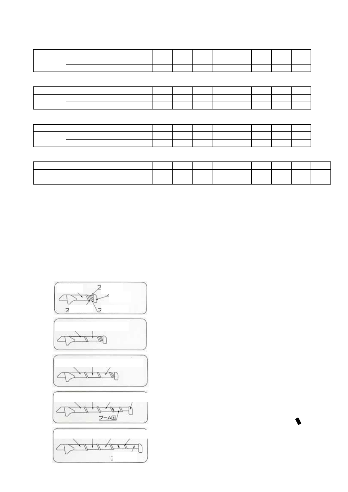
Boom to be extended to: 2.53m~4.075m~5.61m~7.13m~8.65m
Maximum working radius 8.41m
40m/min (At 4th layer on the drum)
Hoisting speed of hook 10m/min (At 4th layer on the drum, with 4-part line hooking)
Extending speed of boom 6.12m/20sec
Raising speed of boom 0°~78℃/11sec
Slewing speed 1.5 rpm
Slewing range 360° (Continuous)
Construction IWRC 6×WS (26) Class B (Breaking load: 43.2kN)
Diameter1×length 8mm×54.0m
Outrigger 2-section for bend and 3-section
Hydraulic Rated pressure Crane:20.6MPa(210kgf/c㎡)、Crawl:21.6MPa(220kgf/c㎡)
pump Rated discharge Approx.38ℓ/min
Rated rotation Approx.2000rpm
Hydraulic oil tank capacity 27ℓ
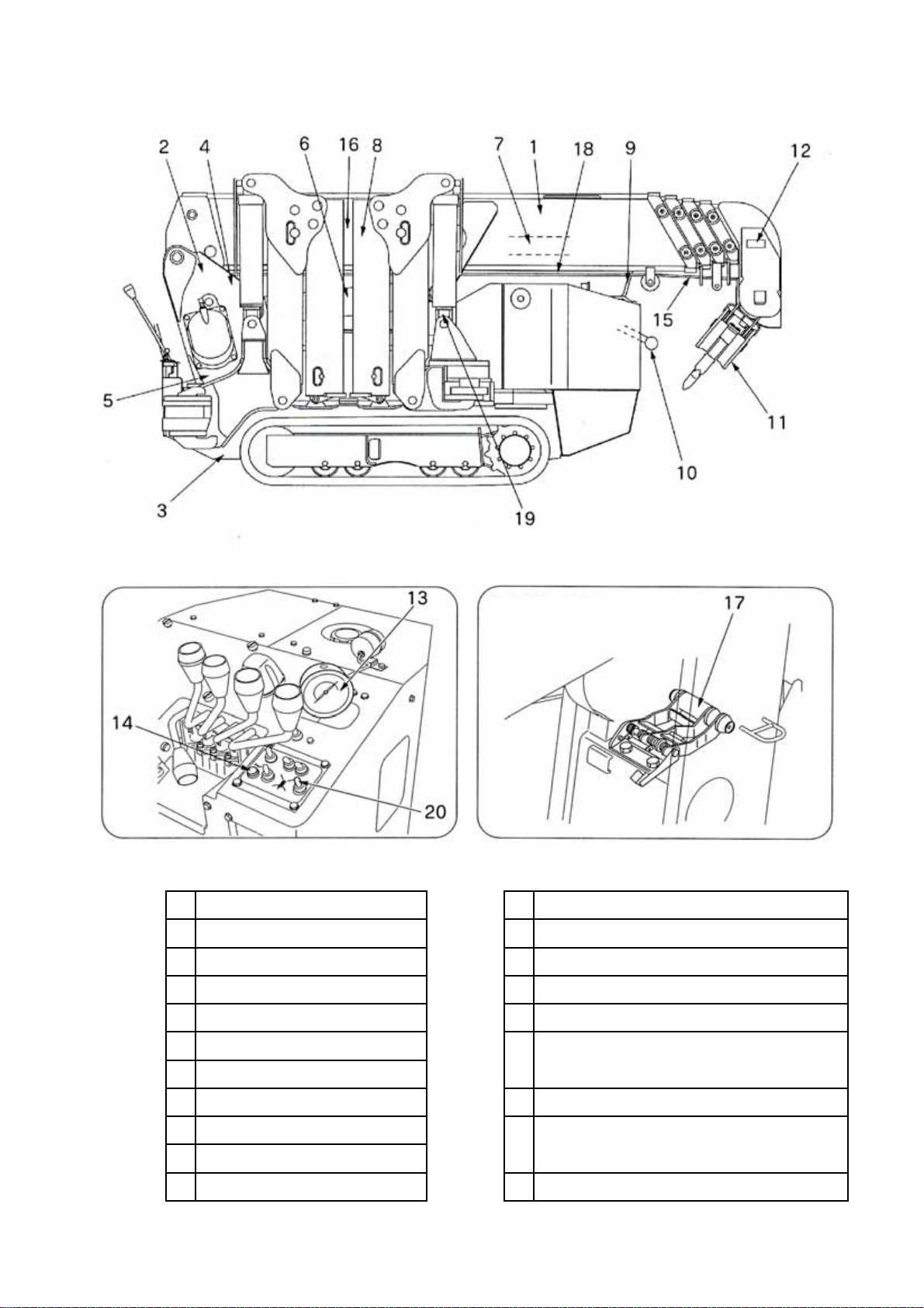
Equipment and construction
Boom telescoping Boom:5-section,Hexagonal box beam
Telescoped by direct pushing of hydraulic cylinder and by wire rope
Boom derricking Direct pushing by hydraulic cylinder(With hydraulic automatic locking device)
Hoisting Hydraulic motor Axial plunger type
Reduction gears Spur-gear reduction
Brake Automatic mechanical brake
Slewing Hydraulic motor Trochoid type(With hydraulic automatic locking device)
Reduction gears Worm-gear+Spur-gear reduction(Supported by ball bearings)
Brake Worm self-lock
Hydraulic pump Variable delivery piston pump
Hooking capacity 2.9t Number of slinging rope:4
Safety device Hydraulic automatic lock
Automatic stop for overwinding/Overwinding alarm/Load indicator
Load indicator(With angle meter)/Level/Alarm buzzer
Hook safety latch
Interlock for crane-crawl lever and outriggers
Weight Approx.1850kg
Crawling device
Crawling Endless rubber crawler
Crawler 180×40×72FR
Length of ground contact 1050mm
Pressure of ground contact 48.0kPa (0.49kgf/c㎡)
Crawling speed Forward/Backward:0~2.3Km/h
Hill-climbing ability 20°
Engine Rated output 9.6kW/2000rpm (13PS/2000rpm)
Crawling Independently driven by hydraulic power
Parking brake Disc brake with hydraulic motor built-in
Starting engine Electric starter
Fuel tank Capacity:7liters
(With hydraulic automatic locking device)(2nd&3rd sections:sequential
actuation,4th&5th sections:simultaneous actuation)
extension.Double acting hydraulic cylinders
with pilot-operated check valves,direct pushing type.
Major specifications (Speed,indicated in the table below is at oil temperature range of 45~
55℃
,
o
p
eratin
g
with noload
,
and at rated
p
um
p
dischar
g
e.
)
Crane capacity(maximum lifting load)
Speed of winding-up(Rope speed)
Hoisting
rope
(4-1)

5.RatedRoadChart
Boomsection 1・1+2
WorkingRadius (m) 1.0 1.4 1.5 1.8 2.0 2.5 3.0 3.5 3.835
RatidRoad 2.9 2.9 2.65 2.25 2.05 1.65 1.3 1.0 0.9
(t) 2.0 2.0 2.0 1.45 1.1 0.65 0.49 0.35 0.25
Boomsection 1+2+3
WorkingRadius (m) 2.2 2.5 2.9 3.0 3.5 4.0 4.5 5.0 5.37
RatidRoad 1.35 1.35 1.35 1.25 1.0 0.8 0.65 0.52 0.43
(t) 0.8 0.65 0.53 0.5 0.38 0.28 0.22 0.16 0.12
Boomsection 1+2+3+4
WorkingRadius (m) 3.4 3.8 4.0 4.5 5.0 5.5 6.0 6.5 6.89
RatidRoad 0.85 0.85 0.75 0.6 0.5 0.42 0.36 0.32 0.27
(t) 0.42 0.34 0.3 0.25 0.19 0.14 0.1 0.08 0.06
Boomsection 1+2+3+4+5
WorkingRadius (m) 3.8 4.1 4.5 5.0 5.5 6.0 6.5 7.0 8.00 8.41
RatidRoad 0.55 0.55 0.45 0.37 0.31 0.27 0.23 0.2 0.15 0.13
(t) 0.35 0.29 0.25 0.2 0.16 0.13 0.1 0.07 0.04 0.03
Caution
●Howboom-sectionsareextended
Boom:1
Allboomsectionsareretracted.
Boom:1+2or2
Boomsection(2)onlyisextended.
Boom:1+2+3or3
Boomsections(2)and(3)areextended.
Boom:1+2+3+4or4
Boomsection(4)isextendedtothemar
k
Boom:1+2+3+4+5or5
Boom-section(2),(3),(4),and(5)arefullyextended.
OutriggerMaxEXT.
OutriggerNotMaxEXT.
OutriggerMaxEXT.
OutriggerNotMaxEXT.
OutriggerMaxEXT.
OutriggerNotMaxEXT.
OutriggerMaxEXT.
OutriggerNotMaxEXT.
■Theratedloadisperformancewhenthecraneisplacedlevelandisbasedonanactualoperatingradius
includingboomdeflectionunderload.Theratedloadisalsobasedonstrengthandstabilityofthecrane.
■Maximumextensionofanoutriggerisaconditioninwhichtheinnerboxisextendedtothemaximumextension
positionandaswinglockpinoftheoutriggerarmisinsertedintothenormalposition.Inotherconditionsthan
theabove,operatewithperformanceofnotmaximumextension.
■Ifanyoneofthefouroutriggersisnotfullyextended,operatewithperformanceofnotmaximumextension.
■Improperset-upoftheoutriggersmaycausethecranetoturnover.Placetheoutriggersonafirmandlevel
surfacewithmaximumextension.Makesure,then,thatlockpinsaresecurelyinserted.
Boom1 Boom4
Boom5
Boom3Boom2
Boom1 Boom2
Boom1 Boom2 Boom
3
Boom1 Boom2 Boom3 Boom
5
Boom1 Boom2 Boom3 Boom
4
Boom5
(5−1)

6.1 Inspection before crane operation
Do not operate the crane for about 2 seconds after starter switch
has been tuened on.
The crane is carrying out the system diagnosis to prevent incorrect operation.
The mode indicator lamp is to be fully lit up for 2 seconds during the
system diagnosis.
If the crane is operated during the system diagnosis, voice message
,“Beep, Service remote control, Service remote control”,sounds and
the crane is turned into inoperable conditions.
In this case, please turn off starter switch. Please operate the crane
after turning on starter switch again and hearing Remote control ready.
After the system diagnosis has been completed, operate the crane
when the voice message “Remote control ready, Remote control ready”
is heard.
6.2 Emergency stop switch
If the crane cannot be operated after the engine has been started, check that emergency stop switch has not been
depressed. Depress emergency stop switch when the crane makes an uncontrolled movement .
All the crane functions stop to be operated.
Emergency stop switch
Depression of switch means the emergency stop is activated.
If the emergency stop switch has been depressed,
depress it again for reset.
Mode indicator lamp blinks [59]
when the emergency stop switch has been depressed .
Mode indicator lamp blinks [58]
when the unloading circuit has been damaged.
State that switch is not pushed
Emergency stop release
State that switch is pushed
Emergency stop operation
Caution
No operation is allowed when resetting the emergency stop switch.
If the emergency stop switch is reset during crane operation, it is very dangerous as the crane may make
an abrupt movement.
Although the engine speed may increase for a short time when the emergency stop switch has been pushed
in again to reset the emergency stop, this is not a fault.
Depression of emergency stop switch allows
the unloading solenoid to magnetize.
Control box Mode indicator lamp
(6-1)

6.3 Shock-less function
In order to preuent a lifted cargo from swinging, it allows the crane to make a
smooth stop when operated through radio remote control.
When making the crane a sudden stop, actuate the “selector switch” controlling
opposite function while the shock-less is functioning.
(Do not pull the speed lever during this operation.)
In order to inactivate the shock-less function, turn ON the “hook winding-down”
switch with the “Mode switch” depressed.
6.4 Interlocking balance control function
This is the function that controls the movement of lever and the engine speed for
every combination of interlocking operation through radio remote control.
Examples listed below are not a fault:
When controlled through radio remote control device, the movement
of lever differs each time of operation or the control lever will not be
shifted to its maximum.
When operation is switched from interlocking to independent, control
speed may become slower than that of the independent operation in itself.
Stop the radio remote control operation once and go back to independent
operation again to return it to the original control speed.
This is a measure preventing its operating speed from making an abrupt
increase when operation is switched from interlocking to independent.
Following gives a serious influence on performance of interlocking operation:
Unspecified hydraulic pump has been mounted.
The rated speed of hydraulic pump has not been set as specified.
Any of control levers has been altered.
Hooking system has been changed.
(6-2)

7.1Manualmode
Radiocontroloperationswitchispushedorifmodeindicatorlamphasdisappeared
bypushingRadiocontrolselectorswitch,themanualoperationispossible.
7.2Radiocontrolmode
Ifthekeyswitchofthetransmitteristurnedon,thestartbuttonispushed,andmodeindicatorlamplights,
theradiocontrollercanbeoperated.
7.3Switchingofmodeindicator(State⇔Operation)
Stateindication Operationindication
(normalcase) Depressbothwinding-upandradiocontrollerselector
switchesatthesametimeorturnOFFpowertocrane
andturnitONagain.
Depressbothwinding-upandradiocontrollerselector
switchessimultaneously.
+
Modeindicatorlampisturnedoff.
Modeindicatorlampislights.
Keyswitch
Startbutton
Radiocontroloperationswitch
(7-1)

7.4Switchingof"shockless"function (Carryitoutwhenitisnotover-wound)
"shockless" No"shockless"
(normalcase) “[-]”appearsontheleftsideofmodeindicator.
7.5Switchingof low-temperatureoperationmode
Low-temperature Low-temperature
operationmode operationmodeON
OFF(normalcase) Modeindicatorshows[06].
Voicemessage,“changecontrolmode”isissued.
Depresstheswitchforstoringhookwiththeswitchfor
slewingC.W.turnedON.
Depresstheswitchforstoringhookwiththeswitchfor
slewingC.C.W.turnedON.
TurnONwinding-downswitchwithpara-hookswitch
depressed.
TurnONwinding-upswitchwithpara-hookswitch
depressed.
(7-2)

7.6Resettingofinterlockingbalancecontrol
Retainingfunctionof Retainingfunctionof
dividingoperationON dividingoperationOFF
(normalcase) Depresstheswitchforstoringhookwiththeswitch Modeindicatorshows[oF].
forboom-downturnedON. Voicemessage,“changecontrolmode”isissued.
7.7Switchingofoutriggerradiocontorolmode
TurnON"modeoperationswitch"tooutriggerside.
Craneoperationmode Outriggeroperationmode
(normalcase) Modeindicatorshows[04].
TurnON"modeoperationswitch"tocraneside. Voicemessage,“changecontrolmode”isissued.
Depresstheswitchforstoringhookwiththeswitch
forboom-upturnedON.
modeopreration
switch
(7-3)

7.8Methodofenginestartandstopthatusesradiocontroller
However,thisoperationispossibleunderthefollowingcondition.
1) Starterswitchmustbeon.
2) Thepowersupplyofthetransmittermustbeon.
3) Theoperationmodemustbearadiocontroll mode.
Enginestop Enginestart
Depresstheswitchformodeselectwiththeswitchfor
slewingC.C.W.turnedON.
Depresstheswitchformodeselectwiththeswitchfor
slewingC.W.turnedON.
(7-4)

8.1 Internal view of control box
Matters to be attended when carrying out electric welding
When carrying out electric welding, a large amount of electric current from the welder flows back
through ground circuit which in turn may damage the control box.
Be sure to observe the following:
(1) Turn OFF the starter switch.
(2) Disconnect the cable from the “-” (negative pole) terminal of battery.
(3) Be sure to connect the ground cable of welder securely to the nearest position from the
point to be welded.
Modo indicator Fuse Package Packing
Radio remote control selector switch
(8-1)

8.2 Mode indicator li
g
htin
g
when it is in normal o
p
eration
××
○×
×○
○○
○○
×○
--
--
--
--
--
×○
--
××
--
Remote
control manual
Automatic stop for leaving minimum wire rope signal is received.
it allows to stop unwinding automatically when remaining wire ropes on the
drum come close to 3 turns so that the rope can not be unwound further.
Current control is in outrigger mode.
Only outrigger operation can be done either manually or remote controller.
No operation but outrigger is possible either manually or by remote controller.
Remote controller is not connected.
Check that remote controller cable is securely connected to connector.
Check remote controller cablel for damage and for break.
Current control is in traveling mode.
No operation but outrigger is possible either manually or by remote controller.
Elements in the mode indicator are to be fully lit up as in[8.8.] for about
2 seconds after the starter switch has been turned ON.
The crane is carrying out system diagnosis while the “mode indicator” is
fully lit up.
What is to be checked during system diagnosis is if;
・Electronic circuit in the control box is functioning correctly,
・Manual control lever is at its neutral position,and
・Remote controller is connected to the crane and the controller functions
normally.
Current control is in radio controller mode.
Current control is in low temperature operation mode (manual mode)
Current control is either on radio control operation mode or on outrigger radio
control mode,but power to transmitter has not been turned ON.
"Rasing boom"operation is being carried out while hook has hit against
weight for over-winding alarm.
(8-2)
ML stop signal is received.
LED
display
Current control is in manual mode.
Hook hits against weight for over-winding alarm (over-wound).
During operation for storing hook.
Current control is in low temperature operation mode (radio controller mode)
Content
Automatic stop release switch ON.

8.3 Mode indicator blinking when it is in wrong operation.
8.4 Mode indication of each operation
Operation Mode
indication Operation
Fastest speed
mode Raising boom 38 Storing hook
Medium speed
mode Lowering boom 39 Mode select
Slow speed
mode Hoisting-up 40 Horn
2 interlocking
operation Hoisting-down 00~0.0 Speed: 0~
100%
3 interlocking
operation Retracting boom
4 interlocking
operation Extending boom
5 interlocking
operation Slewing C.W.
6 interlocking
operation Slewing C.C.W
7 interlocking
operation
When wind-up switch of transmitter and radio control selector switch are pushed
at the same time,it is change to the operation display.
It returns to the state display when wind-up switch of transmitter and radio control
selector switch are pushed at the same time again.
(8-3)
The battery of the radio controller transmitter has decreased.
The emergency stop switch of the radio controller device is pushed.
The crane with the radio controller is operating it while checking the spool neutrality.
The "winding up hook" is operated in automatic stop for leaving minimam wire rope.
LED
display
35
26 36
21
22
23
25
Mode
indication
Mode
indication
28
30
31
24
27
20
37
32
33
34
Operation
It is operated to selector switch of shock-less function while operating the crane.
The manual operation is done at the radio controller mode.
Correspondence
The radio controller is operated at a manual mode.
1. The crane is operated at outrigger mode.
2. Outrigger is operated at the crane radio controller mode.
3. It is operated to switch of outrigger mode while operating the crane.
It is operated to switch of the low temperature operation mode while operating the crane.
Either one of operation such as"winding up hook","extending boom"is being carried out
while hook has hit against weight for over-winding alarm.
The hook storage switch was pushed while operating the crane.
It operates it by an automatic halt condition.

8.5 Error indication
When an error is detected, the mode indicator goes off or blinks and the voice message “Service remote control” sounds.
Mode
indication Trouble Available
operation
None System error
42
43
44
45
46
No operation
is possible. Readjust zero point.
47
Operation is
possible. Turn power ON again.
48 In case where it happens again,
49 replace control box.
50
51 Check transmitter and receiver.
52 After turning power ON again,
53
54 Check connection of cable to receiver.
55 After turning power ON again,
Turn power ON again.
56 System error
No operation
is possible. Turn power ON again.
57
58 Unloading error
Radio controller
cannot be
o
p
erated.
Replace control box.
59
No operation
is possible. Turn OFF both emergency stop switches.
60 Spool neutral error Derrick After turning power ON again,
61 Hoisting
62 Telescoping
63 Slewing Check that manual lever has not been caught.
64 Outrigger
65 Acceleration
66 Outrigger selection switch Front right RET/EXT Damaged switch exchange
67 Front left RET/EXT It is possible to operate it excluding the damaged switch.
68 Rear right RET/EXT
69 Rear left ET/EXT
(8-4)
“Radio controller selector switch”in control box has
been controlled before indicator "8.8" goes off.
Radio
controller
cannot be
operated.
In case where it happens again,
replace control box.
wait until mode on "8.8" indicator goes off to
operate radio controller.
Manual lever (spool) fails
to be returned to neutral
within 2 seconds after
power has been turned
ON.
Measures
Either one of emergency stop switches has been
depressed.
No operation
is possible.
Failure in radio controller receiver Transmitter lever
has been pulled before indication on indicator
“8.8” goes off.
Transmitter switch has be depressed before
indication on indicator "8.8" goes off.Signal from
receiver failed to be received
Operation is
possible. wait until mode on "8.8" indicator goes off to
operate radio controller.
Replace fuse in control box.
Turn power ON again.
In case where it happens again,
replace control box.
“Hook storing/releasing switch”on crane side has
been controlled before indicator "8.8" goes off.
In case where it happens again,
replace control box.
No operation
is possible. wait until “8.8”on mode indicator goes off to
operate radio controller.
If lever has no problem, replace proportional
solenoid valve.
Table of contents
Other Unic Construction Equipment manuals