Unical STILE 27 User guide

INSTRUCTIONS
FOR INSTALLATION,
MAINTENANCE
AND USE
00334578 - 05/13
rev. 0
STILE 27

2
General information
TABLE OF CONTENTS
1GENERAL INFORMATION ............................................................................................................................................................................ 4
1.1 Symbols used in the manual ........................................................................................................................................................................ 4
1.2 Appropriate use of appliance ....................................................................................................................................................................... 4
1.3 Water treatment ............................................................................................................................................................................................ 4
1.4 Information for user ...................................................................................................................................................................................... 4
1.5 Safety warnings ............................................................................................................................................................................................ 5
1.6 Technical data plate ...................................................................................................................................................................................... 5
1.7 General warnings ......................................................................................................................................................................................... 6
2TECHNICAL FEATURES AND DIMENSIONS ........................................................................................................................................... 7
2.1 Technical features ........................................................................................................................................................................................ 7
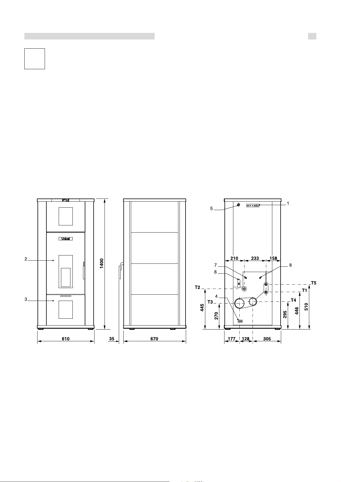
2.2 Dimensions and hydraulic connections ...................................................................................................................................................... 7
2.3 Technical data ............................................................................................................................................................................................. 11
2.4 Supply.......................................................................................................................................................................................................... 11
2.5 Main components ....................................................................................................................................................................................... 12
2.6 General Information .................................................................................................................................................................................... 12
3INSTALLATION INSTRUCTIONS ............................................................................................................................................................... 14
3.1 General warnings ...................................................................................................................................................................................... 14
3.2 Installation standards ................................................................................................................................................................................ 15
3.3 Packaging .................................................................................................................................................................................................. 16
3.4 Installation .................................................................................................................................................................................................. 16
3.5 Flue connection ......................................................................................................................................................................................... 17
3.5.1 Exhaust through external wall........................................................................................................................................................ 18
3.5.2 Exhaust through roof by means of traditional flue ........................................................................................................................ 19
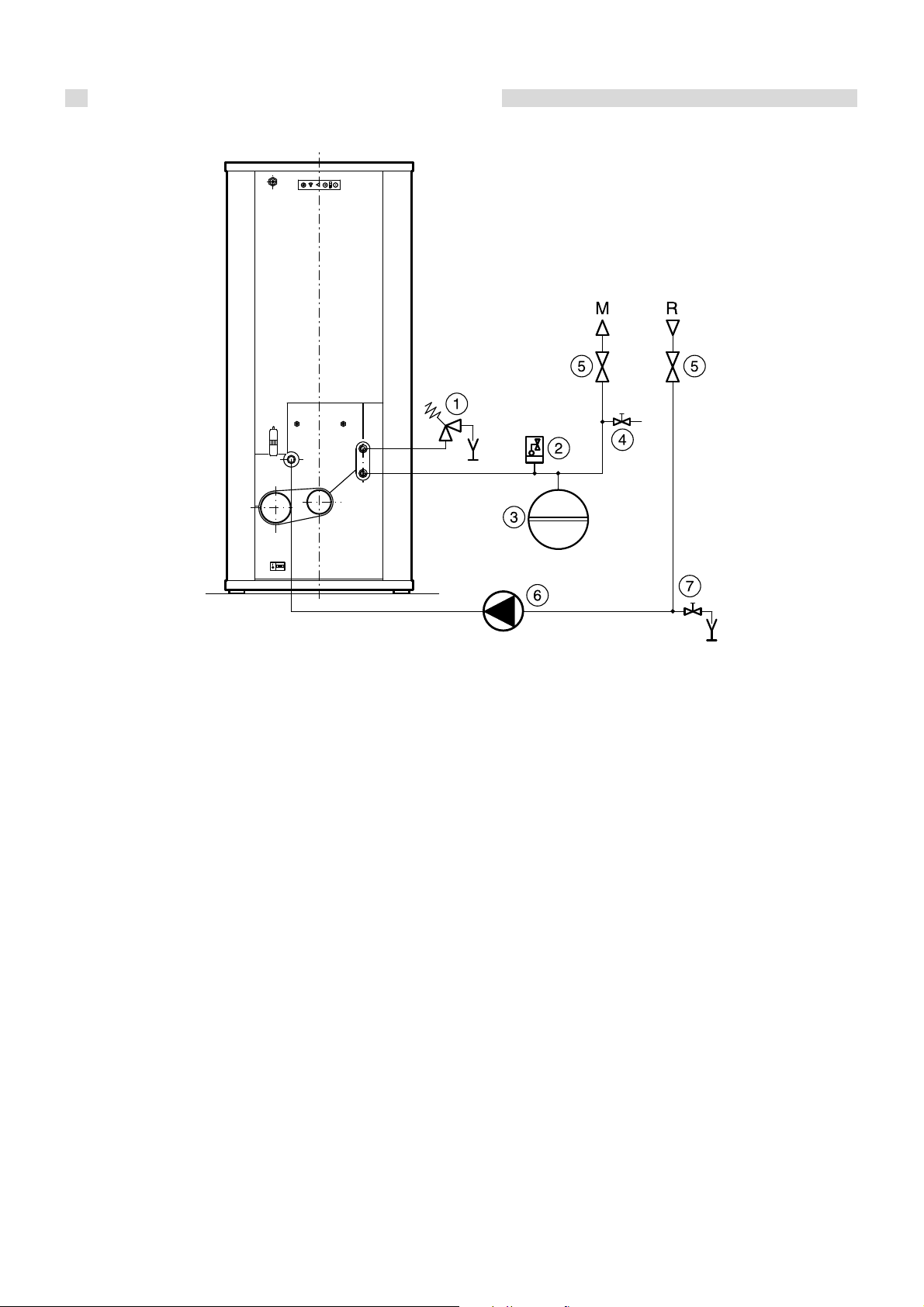
3.6 Connecting heat stove to system ............................................................................................................................................................ 20
3.7 Filling the system....................................................................................................................................................................................... 20
4ELECTRICAL CONNECTIONS .................................................................................................................................................................... 21
5HEAT STOVE START-UP .............................................................................................................................................................................. 24
5.1 Commissioning .......................................................................................................................................................................................... 24
5.2 Initial lighting checks ................................................................................................................................................................................. 24
6INSPECTION AND MAINTENANCE ........................................................................................................................................................... 25
6.1 Troubleshooting ......................................................................................................................................................................................... 28
7PROGRAMMING SETTING ........................................................................................................................................................................... 29
7.1 Using the product ...................................................................................................................................................................................... 29
7.2 Remote control .......................................................................................................................................................................................... 30
7.3 Function of buttons ................................................................................................................................................................................... 32
7.4 Menu ........................................................................................................................................................................................................... 33
7.4.1 User menu ........................................................................................................................................................................................ 33
7.4.2 Menu 01 - set clock ........................................................................................................................................................................ 35
7.4.3 Menu 02 - set chrono ..................................................................................................................................................................... 35
7.4.4 Menu 03 - choose language........................................................................................................................................................... 39
7.4.5 Menu 04 - standby mode ............................................................................................................................................................... 39
7.4.6 Menu 05 - buzzer mode ................................................................................................................................................................. 39
7.4.7 Menu 06 - initial load ....................................................................................................................................................................... 39
7.4.8 Menu 07 - heat stove status .......................................................................................................................................................... 40
7.5 User operating mode ................................................................................................................................................................................ 41
7.5.1 Lighting STILE 27 ............................................................................................................................................................................. 41
7.5.2 Start-up............................................................................................................................................................................................ 41
7.5.3 Failed ignition ................................................................................................................................................................................... 41
7.5.4 Heat stove working......................................................................................................................................................................... 42
7.5.5 Changing room temperature setting .............................................................................................................................................. 42
7.5.6 Using external thermostat / chronothermostat............................................................................................................................. 42
7.5.7 Changing water temperature setting ............................................................................................................................................. 43
7.5.8 The room temperature reaches the set temperature (SET temperature) .................................................................................. 43
7.5.9 The water temperature reaches the set temperature (SET water temperature) ....................................................................... 44
7.5.10 Restarting after extinction having reached set room and/or water temperature ..................................................................... 44
7.5.11 Cleaning the brazier ..................................................................................................................................................................... 45
7.5.12 Heat stove extinction .................................................................................................................................................................... 45
7.5.13 Heat stove off ................................................................................................................................................................................ 46
7.5.14 Heat stove re-ignition ................................................................................................................................................................... 46
7.6 What happens if......................................................................................................................................................................................... 47
7.6.1 The pellet does not light .................................................................................................................................................................. 47
7.6.2 Electric power is missing ................................................................................................................................................................ 47
7.7 Alarms ........................................................................................................................................................................................................ 48
7.7.1 Flue gas temperature probe alarm ................................................................................................................................................ 48
7.7.2 Flue gas overtemperature alarm ................................................................................................................................................... 48

General information
3
7.7.3 Failed ignition alarm ......................................................................................................................................................................... 49
7.7.4 Extinction during working phase alarm ......................................................................................................................................... 49
7.7.5 Screw safety pressure switch alarm............................................................................................................................................. 49
7.7.6 General thermostat alarm .............................................................................................................................................................. 50
7.7.7 Flue gas intake fan fault alarm ....................................................................................................................................................... 50
7.8 Operational mode (technical menu)......................................................................................................................................................... 51
7.8.1 Submenu 08 - 01 - 01 ..................................................................................................................................................................... 53
7.8.2 Submenu 08 - 02 - 01 chimney type ............................................................................................................................................. 53
7.8.3 Submenu 08 - 03 database ............................................................................................................................................................ 53
7.8.4 Submenu 08 - 04 various settings ................................................................................................................................................. 53
7.8.5 Submenu 08 - 05 outputs test........................................................................................................................................................ 53
7.8.6 Submenu 08 - 06 factory settings ................................................................................................................................................. 53
7.8.7 Submenu 08 - 07 reset partial hours ............................................................................................................................................. 53
7.8.8 Submenu 08 - 08 alarm reset ........................................................................................................................................................ 54
7.8.9 Submenu 08 - 09 counter memories ............................................................................................................................................. 54
7.8.10 Flue gas probe calibration ............................................................................................................................................................. 54

4
General information
1.1 - SYMBOLS USED IN THE MANUAL
Pay special attention when reading this manual to the parts marked by the symbols:
NOTE!
Suggestions for the user
ATTENTION!
Possible hazardous situation
for the product and the environment
DANGER!
Serious danger for
personal safety and life
1.2 - APPROPRIATE USE OF APPLIANCE
The STILE 27 appliance has been built according to the current level of engineering and acknowledged
technical safety rules.
Nonetheless, if improperly used, dangers could arise for the safety and the very life of the user and other
persons or damage to the equipment or other objects.
The appliance is intended to operate in hot air circulation heating systems. Any other use must be
considered improper.
UNICAL shall not be held liable for any damage resulting from improper use; in this case the user is fully
responsible for the risk.
Use according to the intended purposes also includes careful compliance with the instructions in this
manual.
1.3 - WATER TREATMENT (see specific booklet)
•The hardness of the feed water conditions the frequency at which the domestic hot water exchanger must be
cleaned.
•If the water has a hardness greater than 15°f, we recommend using water softeners, chosen according to the
characteristics of the water.
•We recommend checking and cleaning the eventual domestic hot water exchanger at the end of the first year
of use and every two years thereafter.
1.4 - INFORMATION FOR USER
•The user must be instructed concerning the use and operation of his heating system, in particular:
•Deliver these instructions to the user, as well as other documents concerning the appliance inserted in the
envelope contained in the packaging. The user must keep this documentation so that it is available
for further consultation.
•Inform the user about the importance of the air vents and the flue gas exhaust system, highlighting
their essential features and the absolute prohibition of modifying them.
•Inform the user concerning controlling the system’s water pressure as well as operations to restore it.
•Inform the user concerning correct temperature control, control units/thermostats and radiators for saving
energy.
•Remember that the system must receive regular maintenance once a year and a combustion analysis
must be performed in the timetable foreseen by standards in force.
•Should the appliance be sold or transferred to a new owner or if you move and
leave the appliance, always make sure that the instruction booklet accompanies it in order to be
consulted by the new owner and/or installer.
1GENERAL INFORMATION
Attention: this manual contains instructions for the exclusive use of the professionally qualified installer and/or
maintenance technician in compliance with current legislation.
The user is NOT qualified to intervene on the heat stove.
The manufacturer will not be held liable in case of damage to persons, animals or objects resulting from failure to
comply with the instructions contained in the manuals supplied with the heat stove.

General information
5
1.5 - SAFETY WARNINGS
ATTENTION!
The appliance must be installed, adjusted and maintained by professionally qualified personnel, in
compliance with standards and provisions in force. Incorrect installation can cause damage to persons,
animals and objects for which the manufacturer cannot be held responsible.
DANGER!
NEVER attempt performing maintenance or repairs on the heat stove on your own initiative.
Any work must be done by professionally qualified personnel.
We recommend stipulating a maintenance contract.
Insufficient or irregular maintenance can jeopardise the operating safety of the appliance and cause
damage to persons, animals and objects for which the manufacturer cannot be held responsible.
Modifying parts connected to appliance
Do not modify the following parts:
-the heat stove
-the air, water and electricity lines
-the flue gas pipe, safety valve and heating water drain pipe
-construction parts which affect the operating safety of the appliance
Attention!
To tighten or loosen the screwed fittings, use only appropriate fixed spanners.
Incompliant use and/or inappropriate tools can cause damage (e.g. water leakage).
Explosive and easily flammable substances
Do not use or store explosive or easily flammable materials (e.g. petrol, paints, paper) in the room where the
appliance is installed.
1.6 - TECHNICAL DATA PLATE
The technical data plate is adhesive and is applied on the back of the heat stove body.
The serial number of the heat stove is on the riveted plaque on the body (upper left side), visible by removing the top.

6
General information
1.7 - GENERAL WARNINGS
The instruction booklet is an integral and essential part of the
product and must be kept by the user or system manager.
Read the warnings contained in this instruction booklet
carefully as they provide important guidelines regarding
installation, use and maintenance safety.
Keep the booklet with care for further consultation.
Installation and maintenance must be performed in compliance
with standards in force according to the instructions of the
manufacturer and by qualified and certified personnel in
compliance with law.
By professionally qualified personnel we mean: personnel
with specific technical skill in the field of heating system
components for civil use, domestic hot water production and
maintenance. Personnel must have the qualifications provided
for by current legislation.
Incorrect installation or improper maintenance can cause
damage to persons, animals or objects for which the
manufacturer is not responsible.
Before performing any cleaning or maintenance, disconnect
the appliance from the energy mains by acting on the switch
of the system or by unplugging it.
Do not obstruct the terminals of the intake/exhaust ducts.
In case of failure and/or malfunctioning of the appliance, switch
it off and do not try to repair it or intervene on it directly. Contact
only personnel qualified in compliance with law.
Any repairs must be performed solely by personnel
authorised by Unical using original spare parts only. Failure to
comply with the above can jeopardise the safety of the
appliance.
To guarantee appliance efficiency and its correct operation,
yearly maintenance must be performed by qualified
personnel.
Should you decide not to use the appliance, parts entailing
potential sources of hazard must be made safe.
Should the appliance be sold or transferred to a new owner or
if you move and leave the appliance, always make sure that
the instruction booklet accompanies it in order to be consulted
by the new owner and/or installer.
Only original accessories must be used for all appliances with
optionals or kits (including electric).
This appliance is intended solely for the use for which it was
expressly designed. Any other use is to be considered
improper and therefore dangerous.

Technical features and dimensions
7
2.1 - TECHNICAL FEATURES
The heat generator mod. STILE 27 is a steel heating stove
operating with wood pellets with the combustion chamber
under negative pressure.
DESCRIPTION OF COMPONENTS:
•Steel heat stove body
•Refractory steel burner
• Front cleaning door equipped with ceramic glass
•Bottom cleaning door
•Automatic combustion air regulator
•Flue gas passage zone that can be inspected
• Powder painted sheet steel casing
2TECHNICAL FEATURES
AND DIMENSIONS
1. Emergency console *
2. Front cleaning door equipped with ceramic glass
3. Bottom cleaning cover
4. Main switch with plug
5. Remote control reception antenna
6. Room thermostat electric connection
7. Manually reset water safety thermostat
8. Manually reset pellet safety thermostat
T1. CH flow (R 3/4)
T2 CH return (R 1)
T3 Chimney connection (ø100)
T4 Air intake connection (ø80)
T5 Safety valve discharge connection (R 3/4)
* Only switches ON/OFF and performs OUTPUT CHANGE, aside from an LED which signals a generic error.
2.2 - HYDRAULIC DIMENSIONS
AND CONNECTIONS
fig. 1

8
Technical features and dimensions
M Heating system flow
R Heating system return
1 Heating system overpressure valve (2.5 bar) (supplied)
2 Automatic release valve (supplied)
3 Heating system expansion vessel (preloaded at 1 bar) (supplied)
4 System filling tap (not supplied)
5 System shut-off valves (not supplied)
6 Main pump (supplied)
7 System drain tap (not supplied)
Indicative hydraulic diagram
fig. 2
Attention!
The diagram above is indicative and can be customised.
For special requirements, please contact our After-Sales Service.
When installing, check the correct direction of the water flow.

Technical features and dimensions
9
Hydraulic dimensions and connections with DOMESTIC HOT WATER PRODUCTION KIT
1. Emergency console *
2. Front cleaning door equipped with ceramic glass
3. Bottom cleaning cover
4. Main switch with plug
5. Remote control reception antenna
6. Room thermostat electric connection
7. Manually reset water safety thermostat
8. Manually reset pellet safety thermostat
9. Domestic hot water production unit
T1 CH flow (R 3/4)
T2 CH return (R 3/4)
T3 Chimney connection (ø100)
T4 Air intake connection (ø80)
T5 Safety valve discharge connection (R 3/4)
T6 Domestic hot water outlet connection
T7. Domestic cold water inlet connection
* Only switches ON/OFF and performs OUTPUT CHANGE, aside from an LED which signals a generic error.
Note: the support bracket of the domestic hot water production unit can be fastened to the ground with plugs.
The maximum clearance of the domestic hot water production unit from the back of the boiler is indicative as it depends on the
length of the flexible hoses.
fig. 3

10
Technical features and dimensions
Indicative hydraulic diagram
fig. 4
M Heating system flow
F Domestic cold water inlet
C Domestic hot water outlet
R Heating system return
1 Heating system overpressure valve (2.5 bar) (supplied)
2 Automatic release valve (supplied)
3 Heating system expansion vessel (preloaded at 1 bar) (supplied)
4 System filling tap (not supplied)
5 System shut-off valves (not supplied)
6 Main pump (supplied)
7 DHW system shut-off valve (not supplied)
8 Domestic cold water inlet filter (not supplied)
9 Differential flow switch (supplied)
10 Plate heat exchanger (supplied)
11 Diverter valve (supplied)
12 Water hammer prevention system (not supplied)
13 System drain tap (not supplied)
Attention!
The diagram above is indicative and can be customised.
For special requirements, please contact our After-Sales Service.
When installing, check the correct direction of the water flow.

Technical features and dimensions
11
2.3 - TECHNICAL DATA
*Pressure drops for flow rate corresponding to a thermal drop of 15K.
** Values calculated based on the Law 10/91 for residential homes with a heat requirement of 30 kcal/hm³. The data is indicative.
*** NOTE: DHW production is subordinated to operation of the system pump. This cannot start up until the water temperature in the heat stove reaches 40°C. Beyond
this threshold it is necessary to consider the time required for the water temperature in the heat stove to reach a degree which allows thermal exchange through
the plate heat exchanger. A pressure drop caused by the thermal exchange is also considered. Therefore, with the heat stove at full capacity and water
temperature of 80°C, with a continuous withdrawal of 10 litres a minute, the outlet temperature from the DHW exchanger will be approximately 40°C with cold water
inlet at approximately 10°C.
The results in the table have been obtained using certified pellets based on the standards DIN 51731, DINplus and ÖNORM M 7135.
Emissions: according to UNI EN 14785
Efficiency: according to UNI EN 14785
(kW) 5,2÷20
NOMINAL OUTPUT
HEAT STOVE CAPACITY
WATER SIDE PRESSURE DROPSA (standard version)*
MAX. WORKING PRESSURE
PELLET TANK CAPACITY
(m.w.c.)
(l) 35
0,3
(bar)
(kg)
2
60
(kW) 8÷27
THERMOCHEMICAL OUTPUT
FLUE GAS TEMPERATURE (°C) max. 180°C - min. 80°C
(W) 395
ELECTRIC ABSORPTION starting
250
full capacity(W)
FLUE GAS MASS FLOW RATE (g/s) 10,20
CO VALUE 13% (%) < 0,04
TOTAL EFFICIENCY (%) 81,48
MINIMUM DRAUGHT (Pa) 10
85
1,65
5,62
min.
max.
PELLET CONSUMPTION (kg/h) min.
max.
10,7
36,4
AUTONOMY (h) at nominal flow rate
at minimum
2.4 - SUPPLY
standard
Controlled combustion system with flue gas
temperature recovery
standard
Flue gas draught control pressure switch
standard
Dual combustion system
standard
Ceramic glass
standard
Two-way remote control
Automatic re-ignition in case of blackout (within 60 seconds)
5-speed forced ventilation
Possibility of setting heat outputs (5 levels)
Weekly programming
standard
standard
standard
standard
MAX HEATABLE VOLUME** (m³) 573
DHW PRODUCTION (see note)*** (l/min.) 10
(kW) 6,8÷22
OVERALL OUTPUT

12
Technical features and dimensions
2.5 - MAIN COMPONENTS
1. Removable top with pellet loading cover
2. Panel board
3. Front door with ceramic glass
4. Pellet combustion crucible
5. Pellet igniter
6. Upper ash cleaning pan
7. Lower ash cleaning pan
8. Heat exchange pipe scraper system
9. Pellet tank
10. Pellet feeding screw
11. Feeding screw motor
12. System pump
13. Combustion flue gas intake/exhaust unit
MC.H. flow
RC.H. return
ACombustion air intake
FCombustion flue gas exhaust
fig. 5
N.B.: The smoke side of the thermal exchange pipes becomes dirty; it is therefore
advised, every time you load pellets, to activate the scraper system (pos. 8) in the
opposite vertical direction for a few seconds to keep them clear.
2.6 - GENERAL INFORMATION
The main feature of the STILE 27 heat stove is that of burning
natural fuel (pellets) obtained in an environmentally-friendly
way from wood industry waste (sawdust, powders). The
sawdust and powders coming from wood processing, after
having been appropriately cleaned and dried, are compacted
at high pressure giving way to pure wood cylinders: the pellet.
Each cylinder can have variable length and thickness,
respectively, between 1÷3 cm long and 6÷8 mm in diameter.
The main features of the pellet are its low moisture content
(lower than 12%), its high density (about 600 kg/m3) as well
as its regularity and compactness providing this type of fuel a
Net Calorific Value (NCV) of 4100÷5000 kcal/kg.
In order to provide STILE 27 with a long lifespan, Unical advises
using good quality pellets.
The pellets used to feed the heating stove must have high
quality features such as, for example, those determined by
standards DIN 51731 and ÖNORM M 7135. The following a
some of their fundamental data.

Technical features and dimensions
13
Quality standards for Unit of measurement ÖNORM M 7135 DIN 51731 DIN plus
wood Pellet
Diameter mm from 4 to 10 from 4 to 10 from 4 to 10
Length mm 5 x D1< 50 5 x D1
Density Kg/dm3> 1,12 1,0 – 1,4 >1,12
Humidity % < 10 < 12 < 10
Ash % < 0,50 < 1,50 < 0,50
Calorific value kWh/kg > 5 4.86 – 5.42 > 5
Sulphur % < 0,04 < 0,08 < 0,04
Nitrogen % < 0,3 < 0,3 < 0,3
Chlorine % < 0,02 < 0,03 < 0,02
Dusts % weight < 2,3 - < 2,3
Bonding agents % of pressed mass < 2 2< 2
1 No more than 20% of the pellets can be 7.5 times longer than the diameter D.
2DIN prohibits use of any added substance. However this prohibition is not valid for small heating systems.
The standard DINplus proposes the combination of quality parameters proposed by the standard DIN 51731 and by the
Austrian standard ÖNorm M 7135.
The pellet, as foreseen by current Italian
legislation governing commodity features of
fuels (DPCM 2.10.1995), must be produced
exclusively with untreated wood sawdust
without other materials added.
It is absolutely forbidden to use any solid or
liquid fuel other than pellets to feed STILE
27.
For best operation of STILE 27, it is
recommended to use pellets the quality of which
is certified by an authorised body.The use of poor
quality pellets can cause STILE 27
malfunctioning and shall terminate the warranty.
Storage and handling of pellets are important operations to
be performed with care:
-The fuel must be stored in a dry place which is not cold;
- Pellets must be moved in such a way to avoid breaking
them up into small powder.
Compliance with these two simple rules provides better
combustion efficiency and conserves the moving mechanical
parts of the appliance.
If STILE 27 remains unlit for long periods
(more than seven days), the tank must be
emptied from residual fuel to keep it from
becoming excessively moist which could
cause the appliance to malfunction.
A high moisture content in the pellet can cause
it to break up into powder generating greater
accumulation of residue in the brazier and
blocking the fuel feed system (screw).

14
Installation instructions
3INSTALLATION
INSTRUCTIONS
3.1 - GENERAL WARNINGS
ATTENTION!
This heat stove is intended solely for the
use for which it was expressly designed.
Any other use is to be considered improper
and therefore dangerous.
This heat stove heats water to a
temperature lower than the atmospheric
pressure boiling temperature.
ATTENTION!
The appliances are designed to be installed
inside suitable rooms or technical spaces
only. The appliances cannot be installed or
operate outdoors. Outdoor installation can
cause malfunctioning and be dangerous.
Choose specifically designed appliances for
outdoor installation.
Before connecting the heat stove, have
professionally qualified personnel:
a) Thoroughly wash all the piping of the system
to remove any residue or impurities which
could jeopardise proper operation of the
heat stove;
b) Check that the chimney/flue has an
appropriate draught, without any
bottlenecks, and that no exhausts from other
appliances are inserted, unless the flue has
been implemented to accommodate several
utilities according to specific standards and
prescriptions in force. Only after this check
can the fitting between the heat stove and
chimney/flue be mounted;
ATTENTION!
The appliance must be installed by a
qualified technician with the technical-
professional requirements according to law
46/90 who, under his own responsibility,
guarantees compliance with standards
according to good practice rules.
The heat stove must be connected to a central
heating system and/or domestic hot water
production network compatible with its efficiency
and output.

Installation instructions
15
3.2 - INSTALLATION STANDARDS
STILE 27 is a heat stove designed to operate with wood
pellets.
It must be installed according to the following standards:
Standard UNI 10683 of 09/2005
Wood or other solid biofuel fed systems.
Installation requirements.
FIELD OF APPLICATION: wood or other solid biofuel fed
systems with a thermochemical input less than 35 kW.
Standard UNI 11263 of 11/2007
Solid biofuels - Characterization of pellet for energy purposes.
Standard UNI 11264 of 11/2007
Solid biofuels - Characterization of wood logs, briquettes and
chips.
LAW March 5,1990 N° 46 and relative applicative regulation
D.P.R. 447 December 6, 1991 (and subsequent amendments).
Safety standards for systems
FIELD OF APPLICATION: without thermal potential limits.
Standard UNI 10847 of March 2000.
Single flue systems for generators fed by solid and liquid fuels.
Maintenance and control. Guidelines and procedures.
FIELD OF APPLICATION: systems fed with solid and liquid
fuels.
LAW January 9,1991 N°10 and relative applicative regulation
D.P.R. 412 26/08/93 (and subsequent amendments), D.P.R.
n°551 of 21.12.1999.
Regulation with amendments to Italian Presidential Decree.
n° 412 concerning design, installation, operation and
maintenance of thermal systems in buildings, in order to reduce
energy consumption.
FIELD OF APPLICATION: without thermal potential limits.
Law n°186 of 01.03.1968
Installation standard IEC 64-8 / II ed.
Electric systems using rated voltage no greater than 1000 V
AC and 1500 V DC.
Installation standard IEC 64-8 / I ed.
Electric systems in buildings intended for residential and
similar use.
This appliance must be installed according to that
indicated by the standards in force in the country where
the heat stove is installed.

16
Installation instructions
3.3 - PACKAGING
The STILE 27 heat stove is delivered encased on a pallet
and protected by cardboard packaging.
After having removed packaging, make sure that
the supply is complete and undamaged.
If in doubt, do not use the appliance and contact
the supplier.
To handle the heat stove and to remove the pallet
below, remove the top and, using appropriate
lifting systems, fasten the upper hook intended
for this purpose.
Keep the packaging material (cardboard boxes,
straps, plastic bags, etc.) out of the reach of
children as they are potential sources of
danger.
Unical will not be held liable for damage to persons, animals
or objects due to failure to comply with the above instruction.
The document envelope, inserted in the combustion chamber,
contains:
-Heating system booklet
-The installation, maintenance and operating instruction
booklet
-Warranty
-Local ventilation requirements adhesive label
If the heat stove is stored for long periods, it should be
adequately protected.
3.4 - INSTALLATION
STILE 27 is a heat generator which withdraws the combustion
air required for the combustion process directly from the
environment in which it is installed.
For this reason, and above all for the safety of the persons
using STILE 27, it must be installed in a sufficiently ventilated
area so that a continuous flow of combustion air is guaranteed.
It is therefore essential to make air vents linked with the outside
which, in compliance with that indicated by Standard UNI
10683, have the following features:
1. Have a free cross-section no less than 80 cm2;
2. Be made close to the floor;
3. Be appropriately protected by metallic mesh or grille so
that the minimum air passage cross-section is not reduced;
4. Be positioned in such a way that it cannot be obstructed.
The correct air influx can also be guaranteed
by using openings towards an adjacent
room as long as that room is provided with
direct ventilation and it has no fire risks such
as depots, garages or storerooms as
regulated by standard UNI 10683.
STILE 27 should be installed in rooms without appliances
which do not operate in an airtight fashion respect to the room
or appliances which can create a vacuum in the room respect
to the outside environment and therefore hinder the draught
of the flue gas exhaust system (UNI 10683).
To make it easier to clean, there must be a clearance space in
front of the heat stove no less than the length of the stove itself.
You must at least make sure that the door can open 90°
unobstructed
The heat stove can be placed directly on the floor as it is
equipped with a self-supporting frame.
When inspecting compatibility of the heating system, you
should make sure that the support surface (floor) has a support
capacity (kg) suitable to bear the weight of the product. If it is
not adequate, suitable safety measures should be taken (e.g.
load distribution plate).
Furthermore, should the floor be made of combustible material
(such as parquet) it should be protected by using a sheet of
fireproof material underneath STILE 27 sufficiently wider than
the base.
When installation has been performed, the heat stove must
be horizontal and stable, in order to reduce vibrations and
noise.
However clearance space must be left behind the heat stove
and on both sides to allow the casing to be opened to service
the fan and the pellet feeding screw.
During installation, place the outermost
clearance point of STILE 27 at least 80 cm
from combustible and/or flammable
material. If this distance cannot be
maintained, a thermal protection should be
arranged (UNI 7129, UNI 10683).
Do not approach or touch the outer surfaces
of the combustion chamber with flammable
material as it can reach high temperatures
following continuous use.

Installation instructions
17
3.5 - FLUECONNECTION
To connect the flue gas exhaust pipe, local and national
standards must be respected (see Standards UNI 7129 and
UNI 10683).
The chimney is of the utmost importance for correct heat stove
operation: it is therefore necessary that the chimney be
waterproof and properly insulated.
Old or new chimneys, built without respecting the specific
requirements, can be recovered by “piping” the chimney itself.
It will be necessary to introduce a metallic pipe inside the
existing chimney and insulate the space between the metallic
pipe and the chimney.
Chimneys made of prefabricated blocks must have perfectly
sealed joints to avoid that flue condensate smudge the walls
due to permeation.
The entrance to the chimney should be at a 45° angle.
At the base of the chimney a flue inspection opening has to be
made.
It is recommended to insulate the pipe connecting to the
chimney to reduce heat loss and noise.
The dimensions of the chimney must guarantee the necessary
draught required to properly operate the heat stove.
An insufficient draught, besides causing smoke leakage,
considerably reduces the heat output. On the contrary, an
excessive draught causes an abnormal heat output increase,
a higher flue gas temperature in the chimney and too much
fuel consumption.
Use only exhaust pipes suitable for the type
of fuel used.
The supplier will have no contractual or extra-
contractual liability for damage caused due
to incorrect installation and use and anyway
failure to comply with the instructions
provided by the manufacturer.
It is prohibited to exhaust STILE 27
combustion products in shared smoke
pipes.
The flue must comply with standards in
force.
The flue gas chimney must be made properly
to favour the normal flow of flue gas from
the combustion chamber towards the
outside in the case of a power outage.
Remember that the elimination of excess heat is managed
optimally by the electronic control unit (modulation,
extinction phase etc.).
The following are the main features of the flue gas exhaust
pipe according to that established by standards UNI 7129
and UNI 10683:
-The flue gas exhaust must be equipped with inspection
plugs;
-The minimum height of the pipe connected directly to the
flue gas exhaust of STILE 27 is between 2÷3 m;
-If a horizontal section is inevitable, it is recommended that
it be no longer than 1.5 m at most and sloping 3÷5% to
favour the escape of the flue gas;
-Use of a weatherproof terminal to avoid altering the
slight state of overpressure found in the flue (do not fit a
horizontal section at the end of the pipe);
-The exhaust ducts must be made with material resistant to
combustion products and condensation (the inspection
plug can drain any condensation which may be formed);
-Pipes must be built in such a way to guarantee maximum
smoke tightness (UNI 10683);
-It is recommended to insulate the exhaust pipe, especially
the outside part exposed to foul weather.
Do not make sections fully horizontal.
There must be no flue gas exhaust hoods installed or
already existing in the room where the heat generator is
installed to avoid creating a vacuum in the environment.
It is prohibited to close the air vents.
It is forbidden to exhaust flue gas through the wall.
Have the flue cleaned at least once a year; we therefore
recommend having both the chimney and the flue gas
fitting thoroughly cleaned.
Should the flue or piping catch fire,
immediately switch STILE 27 off and
disconnect it from the household electrical
mains.
fig. 6
Weatherproof
terminal
1.5 metres
2-3 metres min
H > 4 metres
Soot container
with
condensation
drain

18
Installation instructions
3.5.1 - EXHAUST THROUGH EXTERNAL WALL
One of the installation solutions which can be adopted is that
of positioning STILE 27 near a perimeter wall of the home so
that flue gas is discharged directly outside. Here are some
guidelines from the standard UNI 7129 for this particular type
of configuration:
-Always provide an inspection plug which allows you to
perform efficient and periodical cleaning as well as draining
any condensation formed;
-The chimney must be strictly wind and rain proof;
-Appropriately insulate the flue gas exhaust pipe in the
section passing through the wall.
The flue gas exhaust pipe, if completely outside, should be
made in double wall stainless steel to guarantee both greater
resistance to atmospheric agents and a sufficient flue gas
temperature.
fig. 7
Soot container with
condensation drain
Weatherproof
terminal

Installation instructions
19
3.5.2 - EXHAUST THROUGH ROOF BY MEANS OF TRADITIONAL FLUE
The pellet combustion flue gas can also be discharged using
a traditional pre-existing flue as long it is made up to standard
(see UNI 10683).
We will briefly list some of the main features highlighted by
the standard which characterise a good chimney:
-Adequate insulation especially in the outside section
exposed to the atmosphere;
-Constant internal cross-section (there must be no cross-
section constrictions);
-Made with material resistant to high temperatures, to the
action of combustion products and to the corrosive action
of condensation which could be formed;
-Predominately vertical with deviations no greater than 45°;
It is recommended to provide a solid material and/or
condensation collection chamber which can be inspected
through an airtight door.
It is recommended to abide by that established by standards
UNI 9615 and 9731 for the dimensioning of the chimney cross-
section and anyhow not to make pipes with a diameter less
than 100 mm.
If there are larger cross-sections, a steel pipe must be inserted
inside the masonry duct.
The steel pipe must be sufficiently insulated
with high temperature resistant material and
sealed from the outer chimney.
fig. 8
Inspectionable soot
container with possible
condensation drain

20
Installation instructions
3.6 - CONNECTING HEAT STOVE
TO SYSTEM
Attention!
Make sure that there are no mechanical
tension points while connecting the pipes to
avoid the risk of leakage!
Heating flow and return pipes must be connected to the heat
stove at the respective fittings as indicated on page 8.
For the STILE 27 heat stove equipped with the domestic hot
water production kit, see the diagram on page 10.
For the dimensioning of the heating circuit pipes, you must
take into account pressure drops caused by radiators,
thermostatic valves, radiator stopping valves and by the
configuration of the system.
The laying of the pipes must be designed taking every
necessary precaution to avoid air pockets and to facilitate
continuous degassing of the system.
Make sure that the pipes of the water and
heating system are not used as earthing
electrodes of the electric or telephone system.
They are absolutely not suitable for this type of
use. Serious damage could result for the piping,
heat stove and radiators in a short amount of
time.
3.7 - FILLING THE SYSTEM
Attention!
Do not mix the heating water with incorrect
concentrations of antifreeze or anti-
corrosion substances! This could damage
the gaskets and cause noise during
operation.
Unical will not be held liable for damage to
persons, animals or objects due to failure
to comply with the instruction above.
After completion of all the hydraulic connections, fill the
heat stove and proceed with the inspection of soundness
of all the connections.
This operation must be performed carefully, respecting the
following phases:
-open the radiator air release valves;
-open the filling tap gradually, making sure that the
automatic air release valves installed on the system work
properly;
-close the radiator air release valves as soon as water
comes out;
-by means of the pressure gauge inserted on the system,
check that pressure reaches approximately 1 bar;
-close the filling tap of the system and bleed air once again
through the radiator air release valves;
-make sure that all the connections are watertight;
-after commissioning the heat stove and bringing
the system to the operating temperature, stop the
pumps and repeat the air bleed operations;
-let the system cool off and, if necessary, return
the water pressure to 1 bar.
NOTE
In systems equipped with closed expansion
vessel, the water pressure in the heating system
- with the system cold - must not drop below 1
bar; open the filling tap when pressure is too low.
This operation must be performed with the system
cool.
The pressure gauge fitted on the system allows
you to read circuit pressure.
NOTE
If the system was without electric power, after a
certain idle period, the pump/s could be blocked.
Before turning on the main switch, the pump must
be unblocked by operating as follows:
Introduce a screwdriver in the hole below the
protective screw in the centre of the pump
intended for this purpose and turn the pump shaft
clockwise.
After having unblocked the pump, tighten the
protective screw and make sure there is no water
leakage.
ATTENTION!
After removing the protective screw, a small
amount of water could leak out. Dry off all wet
surfaces before powering the boiler.
fig. 9
Table of contents