Uniflair Aquaflair 00182 User manual

Versione: 1.4 - Data: 01.12.2000
Pag.: 48 - File: A-B-C-Ara14en
ARA
AIR-COOLED WATER CHILLERS
00182 - 00202 - 00232 - 00252 - 00302 - 00403 - 00504
AIR-COOLED HEAT PUMPS
00182 - 00202 - 00232 - 00252 - 00302 - 00403 - 00504
FREE COOLING CHILLERS
00182 - 00202 - 00232 - 00252 - 00302
ULTRA-LOW NOISE LEVEL FREE COOLING CHILLERS
00152 - 00182 - 00202 - 00232 - 00252 - 00302
INSTRUCTION MANUAL
© UNIFLAIR 2000.
GB
A - D - L
H - P - Q
E
M

2
UNIFLAIR ITALIA S.r.l.
Via dell’Industria, 10
35020 BRUGINE (Padova) Italy
Tel. +39 (0)49 9713211
Fax. +39 (0)49 5806906
Internet: www.UNIFLAIR.com
E-Mail: info@UNIFLAIR.com
Release: 1.4 Date: 01 - 12 – 2000
Checked by:

3
CONTENTS
WARNINGS Page. 4
SYMBOLS USED 5
SAFETY 5
GENERAL DESCRIPTION 6
Documentation included with the unit 6
Available versions and accessories 7
Data plate 8
General description and intended use of the unit 8
Access to main components 10
Description of the main components of the unit 12
Free cooling System - Free cooling 14
Recovery of condensation heat 15
INSTALLATION 16
Transport and handling 16
Receiving and storing the unit 17
Positioning the unit – working space 18
Water connections 19
Low-temperature operation with anti-freeze mixture 20
Guide to sizing of the expansion tank 21
Electrical connections 22
Remote control, local networks and supervision systems 24
Check list for start-up and testing 27
PROGRAMMING AND REGULATION 29
Microprocessor control 29
Introduction 29
Basic control 29
Advanced mP20 control 29
Regulation of cooling capacity 31
Setting the safety devices 32
TECHNICAL DATA 33
Current absorption – Cooling only versions and Heat Pumps 33
Current absorption – Free cooling version 34
Current absorption – Ultra-Quiet free cooling version 35
Dimensions and weights 36
ARA Basic version (cooling only) - Models 00182 - 00232 37
ARA Heat pump - Models 00182 - 00232 37
ARA Ultra low-noise version - Models 00182 - 00232 37
ARA Basic version (cooling only) - Models 00252 - 00504 38
ARA Heat pump - Models 00252 - 00504 38
ARA Ultra low-noise version - Models 00252 - 00504 38
ARA Free cooling version - Models 00182 - 00232 39
ARA Free cooling Low Noise Level - Models 00152 - 00232 39
ARA Free cooling version - Models 00252 - 00302 40
ARA Free cooling Low Noise level - Models 00252 - 00302 40
PROBLEM SOLVING 41
Guide to problem solving 41
Bleeding the water circuit 44
Refrigerant charge 44
Maintenance and cleaning 46
Changing the air filter 46
APPENDIX
Instruction manual for ARA microprocessor controls

4
This unit has been subjected to risk analysis under EC Directive 98/37/CEE (89/392/CEE). The technical
solutions implemented during the design phase are described in the unit’s technical file.
This equipment is manufactured to function safely for the purposes for which it was designed as long as the
installation, operation and maintenance are carried out according to the instructions in this manual
and on the labels attached to the unit.
Warnings in this manual which are particularly important for user safety are shown by this danger symbol.
IMPORTANT WARNINGS
This unit contains refrigerant gas circuits, chilled water under pressure, live electrical components, hot
surfaces, sharp edges (the fins on the coils) and rotating devices such as the fans.
All service and maintenance operations which require access to the inside of the unit while it is in
operation must be performed by qualified and experienced personnel who are aware of the necessary
precautions.
Before accessing the inside of the unit, disconnect it from the electrical power supply.
In any case, all safety legislation of the installation location must be followed.
In the event of fire water and other conductive substances must not be used to put out the fire near live
electrical components. This warning must be displayed on notices in the unit installation location.
If the refrigerants used come into contact with fire they decompose, forming acids and other irritants. The
smell of these substances, even at concentrations below danger levels, gives enough warning to allow
evacuation of the area at risk.
Make sure that the mains supply to the unit is the same as that shown on the rating plate.
Drain all water from the system before the winter season to avoid freezing.
In periods in which the temperature may fall below 0°C, empty the unit in order to prevent the serious damage
caused by the formation of ice.
This precaution is not necessary if the unit is charged with an appropriate anti-freeze mixture.
Free cooling chillers must be loaded with anti-freeze.
If the unit is fitted with the optional heating cable, it must be turned off without cutting the electrical power
supply.
Install a mechanical filter in the section of tubing near the intake of the unit to prevent the fouling of the
heat exchanger with pieces of welding or flakes of oxidised metal from the water mains.

5
SYMBOLS USED
SYMBOL MEANING SYMBOL MEANING
DANGER MOVING COMPONENTS
IMPORTANT WARNING HOT SURFACES – DANGER OF
BURNING
HIGH VOLTAGE – ELECTRICAL
RISK
SHARP EDGES
SAFETY
The new range of UNIFLAIR ARA water chillers and heat pumps features state-of-the-art technology to give
maximum reliability, safety, quietness of operation and respect for the environment.
1) RELIABILITY: Trouble-free operation of Uniflair precision chillers is ensured by rigorous production
process controls under ISO 9001-certified quality procedures:
•quality control of components;
•pressure testing of refrigerant and water circuits;
•testing of current absorption and IEC safety testing;
•calibration and testing of instruments and safety devices;
•final testing of unit under operating conditions
2) ACTIVE SAFETY: UNIFLAIR safety and control systems have a supervision and prevention function
with:
•automatic blocking of components in dangerous conditions;
•indication of function status; reading and continuous display of circulating fluid temperature;
•management of compressor start-ups to reduce excessive switching on and off
•compressor start timing to reduce total unit start-up current
•indication of anomalous function conditions and/or alarms.
3) PASSIVE SAFETY: The essential functions of UNIFLAIR chillers are protected against anomalous
function conditions and potential damage with:
•high and low pressostats on the refrigerant circuit (HP with manual re-set)
•safety valve on the high pressure refrigerant line
•anti-freeze protection to prevent freezing of the evaporator, pump and tank
•compressor motor electrical protection
•standard differential flow gauge
•water circuit safety (with optional pump group)
•compressor crankcase heater (standard on free-cooling and heat pump versions).
4) PERSONAL SAFETY. The design and cabling of all UNIFLAIR chillers conforms to IEC electro-
technical norms. Electrical panels have auxiliary 24V circuits and are equipped with:
•general switch and door lock switch;
•automatic circuit-breaker switches;
•double protection panel on fan compartment.
The fans are protected by an external metal grille which conforms to applicable safety norms.

6
GENERAL DESCRIPTION
DOCUMENTATION INCLUDED WITH THE UNIT
Every ARA chiller is delivered complete with the following documentation:
•ARA and microprocessor control instruction manuals
•Unit installation diagrams
•Diagrams of the refrigerant and hydraulic circuits of the unit
•Electrical diagrams
•List of spare parts
•CE declaration with list of European directives and norms to which the unit conforms
•Guarantee Conditions.

7
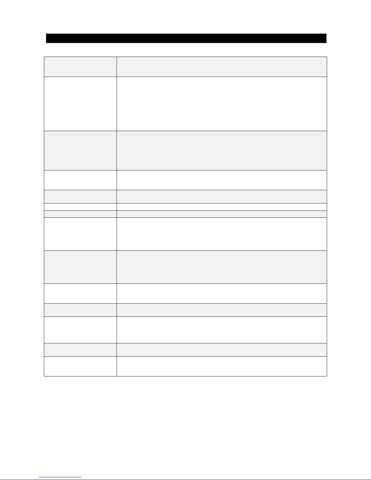
AVAILABLE VERSIONS AND ACCESSORIES
Models ARA00152 (only M versions), ARA00182, ARA00202, ARA00232, ARA00252,
ARA00302, ARA00403 (not supplied for E and M versions), ARA00504 (not
supplied for E and M versions)
Configurations A : Basic version: mechanical cooling with on-off condensation control
D: Basic version with modulating condensation control
L: Ultra low-noise version with modulating condensation control
H: Heat pump with on-off condensation control
P: Heat pump with modulating condensation control
Q: Ultra low-noise heat pump with modulating condensation control
E: Free cooling version with modulating condensation control
M: Ultra low-noise free cooling version with modulating condensation control
Pump group Group with 1 type A pump (0.9 kW)
Group with 2 type A pumps (0.9 kW)
Group with 1 type B pump (1.1 kW)
Group with 2 type B pumps (1.1 kW)
Group with 1 type C pump (1.85 kW)
Group with 2 type C pumps (1.85 kW)
Reservoir tank
(only with pump group)
Tank type “A” (210 litres)
Tank type “B” (300 litres)
Tank type “C” (500 litres)
Heat recovery Partial heat recovery (with modulating condensation control as standard - not supplied
for heat pump versions)
Power supply 400V/3ph+N/50Hz
Electrical accessories Power phase correction capacitors
Control Basic control (not available on free-cooling versions)
Basic control with remote terminal (not available on free-cooling versions)
mP20 control without user terminal (not available on heat pumps)
mP20 control with local user terminal (not available on heat pumps)
mP20 control with remote user terminal (not available on heat pumps)
Serial connections LAN (with mP20 control)
RS485 serial output (with basic control)
RS485 serial output (with mP20 control)
RS422 serial output + LAN (with mP20 control)
RS485 serial output + LAN (with mP20 control)
Refrigerant R22
R407C
R134a
Norms ISPESL (Italian)
TÜV (German)
Refrigerant Accessories Anti-freeze heater on evaporator (not supplied for Free cooling versions)
Anti-freeze heater on pumps (not supplied for Free cooling versions)
Anti-freeze heater on tank (not supplied for Free cooling versions)
High/Low pressure manometers
Pressure sensors Low pressure sensor (with mP20 control only)
High pressure sensor
Options Rubber anti-vibration feet
Coil protection grilles
Metal filters for free cooling coil.

8
DATA PLATE
The chiller data plate is in the electrical panel and gives the following information:
•Model of the unit
•Serial number
•Voltage, number of phases and power supply frequency for primary and auxiliary circuits
•Current and power absorbed
•OA (Operating current), FLA (Full load current) and LRA (Locked rotor current)
•Safety device settings
•Refrigerant type and charge in kg for each circuit.
MODEL SERIAL No.
POWER SUPPLY VOLTAGE
CURRENT
OA FLA LRA KW TOTALI
SAFETY DEVICE SETTINGS
REFRIGERANT
GENERAL DESCRIPTION AND INTENDED USE
Air-cooled and water-cooled ARA air-cooled liquid chillers and heat pumps are designed for outdoor
installation in comfort and industrial applications. The chilled water produced can be sent to fan coils or room
air conditioning units or can be used for industrial process cooling.
Units fitted with the mP20 microprocessor control can be connected in parallel on a single water circuit
thanks to the possibility to connect the microprocessor control boards in a local network. The cooling capacity
of the system can therefore be altered at any time.
FUNCTION LIMITS
In free cooling and heat pump versions or in applications which require the production of chilled water in
winter as well as summer, an anti-freeze mixture (water and ethylene glycol) must be used (see “Low-
temperature operation with anti-freeze mixture”). The standard cooling-only unit can operate at air
temperatures up to +46°C.
EASE OF INSTALLATION AND MAINTENANCE
The compact dimensions and reduced weight of these chillers facilitates installation even where space is
limited. All models are fitted with a main switch to enable direct connection to the mains power supply without
the need for an external switch; short-circuit protection fuses should be fitted however.
All units are assembled and fully tested in the factory, making installation simply a question of connection to
the electrical power supply and water circuits. An important feature of the design is the positioning of
components to allow easy access for service and maintenance.

9
RESISTANCE TO THE ELEMENTS
Uniflair chillers boast excellent corrosion resistance and are built to withstand the harshest of conditions. The
structure is in galvanised steel sheet painter with polyester powder; all external fastenings are in stainless
steel.
LOW NOISE LEVELS
Even the basic units have very low noise levels thanks to large exchange surfaces and low fan running
speeds. For special applications where near-silent operation is required there are ultra-low noise versions
available; these units have vibration dampers on the compressor output, sound insulation on the compressor
housing and modulating fan speed control.

10
ACCESS TO MAIN COMPONENTS
COMPRESSOR HOUSING
To access the compressor housing, remove the 8 fixing screws 1and lift panel Ausing the two front
handles B. Removing panel Agives access to the compressor housing, the microprocessor control user
terminal and to the optional high and low pressure manometers..
A
C
1
3
4
B
2
5IG
DANGER – HOT SURFACES! RISK OF BURNING. When panel Ahas been removed the compressor and
refrigerant tubes are exposed – during normal unit operation these components are very hot and can cause
burns.
IMPORTANT: Removing panel Adoes not stop the unit and the power supply to the compressors is not
interrupted. For service and maintenance, the main switch IG must be turned off (position ‘O’).
ELECTRICAL PANEL
To access the electrical panel move the main switch IG to position “O” and turn the two screws 41/4 turn.
This enables panel C, hinged at the base of the electrical panel to be opened.

11
PUMP GROUP
To access the optional pump group and the free cooling pump remove the six fixing screws 6and remove
panel Dusing front handle E. To avoid contact with the fan blades there is a further steel protection panel
F, fixed with screws.
D
6
7
E
IMPORTANT: Before removing panel Dswitch off the unit by moving main switch IG to position ‘O’ to make
sure that there is no power supply to the compressors and circulation pumps.
ATTENZIONE
PRIMA DI QUALSIASI INTERVENTO LEGGERE ATTENTAMENTE IL LIBRETTO DI ISTRUZIONI.
APPARECCHIO IN TENSIONE E CON ORGANI ROTANTI: PRIMA DI INTERVENIRE SU QUALSIASI
PARTE ELETTRICA OPPURE SUL VENTILATORE/I TOGLIERE TENSIONE ALL’APPARECCHIO.
WARNING
BEFORE ANY OPERATIONS ON THIS UNIT READ THE INSTRUCTION MANUAL CAREFULLY.
THIS EQUIPMENT CONTAINS COMPONENTS AT MAINS VOLTAGE AS WELL AS ROTATING FANS:
DISCONNECT POWER BEFORE ANY OPERATION ON ELECTRICAL COMPONENTS OR FANS.
ACTHUNG
VOR ALLEN ARBEITEN AN DIESEM GERÄT IST DIE BEDIENUNGSANLEITUNG GENAU STUDIEREN.
DIESES GERÄT ENTHÄLT BUTEILE, DIE UNTER SPANNUNG STEHEN SOWIE SICH DREHENDE
VENTILATOREN: VOR ARBEITEN IM GERÄT IST DIE NETZZULEITUNG ABZUSCHALTEN.
ATTENTION
LIRE ATTENTIVEMENT LE MANUEL D’INSTRUCTIONS AVANT TUOTE INTERVENTION.
CET EQUIPEMENT UTILISE DES COMPOSANTS ÉLECTRIQUE SOUS TENSION ET DES PIECES EN
MOUVEMENT. COUPER L'ALIMENTATION AU DISJONCTEUR AVANT TOOTE INTERVENTION SUR
LES COMPOSANTS ELECTRIQUES.
ATENCION
ANTES DE CUALQUIER INTERVENCIÓN LEER ATENTAMENTE EL MANUAL DE INSTRUCCIONES.
APARATO BAJO TENSIÓN Y CON COMPONENTES ROTANTES. ANTES DE INTERVENIR SOBRE
CUALQUIER PARTE ELÈTRICA O SOBRE EL VENTILADOR/ES QUITAR TENSION AL APPARATO.

12
DESCRIPTION OF MAIN COMPONENTS
STRUCTURE
These units are normally installed outdoors, often on the roof of a building. For this reason the structure of the
unit is made entirely in galvanised steel, painted with corrosion-resistant polyester powder. All external
fastenings are in stainless steel.
The panels can be easily removed to facilitate maintenance and all internal components can be accessed via
two sides of the unit.
COMPRESSORS
Ultra-reliable rotating SCROLL compressors from a leading
manufacturer are used (in tandem on models 00403 and
00504). All ARA units have two independent refrigerant
circuits, ensuring at least 50% capacity in the unlikely event
of a fault in one of the circuits.
The microprocessor control manages the switching on and
off of the compressors in order to ensure effective control
of unit capacity; capacity steps depend on the type of
control fitted; in the case of the mP20 control the steps are:
0 - 45 - 100% on models 00182 and 00232
0 - 50 - 100% on models 00202, 00252 and 00302
0 - 45 - 70 - 100% on model 00403
0 - 25 - 50 - 75 - 100% on model 00504
These units are available in versions for use with HCFC-
R22 and HFC-R407C (environment-friendly) refrigerants.
Units for operation with R134a are available on special
order from UNIFLAIR ITALIA Srl.
In order to prevent the refrigerant fluid diluting the oil and
creating foam when the unit is started all free cooling or
heat pump ARA models are fitted with oil heaters which
switch on automatically when the compressor stops.
Each compressor is fitted on rubber mountings to reduce
vibration transmission.
FANS
The sickle-blade axial fans are directly connected to external rotor motors which can be fitted with voltage
modulation speed control. The metal support grille conforms to all the main safety standards. The motors
have class F insulation and IP44 protection under DIN VDE 0470 section 1/11.92 and EN 60529.
Modulating condensation temperature control is available with fan speed regulation. This control is standard
with certain unit configurations (ultra low-noise versions, free cooling versions, partial heat recovery).
EVAPORATOR
The brazed plate heat exchangers are in AISI 316 stainless steel. The exchanger is fully lined with closed-cell
expanded polyurethane to prevent the formation of condensation and to limit heat loss. Given the internal
volume and operating pressure, the evaporator does not need ISPESL or TÜV homologation under the
standards for pressurised containers.

13
CHILLED WATER PUMP GROUP (optional)
The pump group for the circulation of chilled water is available in
different configurations:
- one pump (type “A”, “B” or “C”);
- two pumps (one in stand-by);
- one pump plus reservoir tank;
- two pumps (one in stand-by) plus reservoir tank.
The pumps, with 2-pole motors (2900 rpm), are fitted with the related
connections, collectors and electrical panel (located in the main
electrical panel housing). The pump panel controls rotation of operation
between the two pumps on the basis of run time or alarms. The
electrical panel contains the run hour counter for each pump and red
LED alarm indicators.
Pump body, flange and impeller are AISI 304 stainless steel, insulation
is class F and protection is to IP55. The materials used ensure correct
pump operation with liquid temperatures from -10°C to +85°C.
CIRCULATING PUMPS
ARA 00152 00182 00202 00232 00252 00302 00403 00504
Solo freddo n.a. A - B - C B – C CCooling onl
y
Pompa di calore n.a. A - B - C B – C CHeat pump
Free cooling A - B – C B – C n.a. n.a. Free cooling
Free cooling silenziato A - B – C B – C n.a. n.a. Low noise - Free cooling
n.a. = Non disponibile n.a. = Not available
RESERVOIR TANK
ARA 00152 00182 00202 00232 00252 00302 00403 00504
Solo freddo n.a. AA – B A - B - C Cooling onl
y
Pompa di calore n.a. AA – B A - B - C Heat pump
Free cooling AA – B n.a. n.a. Free cooling
Free cooling silenziato AA – B A - B - C n.a. n.a. Low noise - Free cooling
n.a. = Non disponibile n.a. = Not available
FINNED COILS
In air-cooled versions the condenser consists of coils with aluminium fins and copper tubes mechanically
expanded to obtain an optimum metallic contact and maximum exchange efficiency. The coil has a very large
surface area for operation with high ambient temperatures and has an integrated super-cooling circuit.
If there are harsh conditions in the installation environment, various treatments are available for the
exchanger: pre-painted aluminium, copper-copper protection and cataforesis aluminium treatment;
cataforesis provides the best compromise between cost and performance.

14
FREE COOLING
During normal chiller functioning, the water consumed is treated in the brazed plate heat exchanger. When
the external air temperature drops to such a level as to allow water pre-cooling, the control activates a
recirculation pump which sends the water to a finned pipe coil, mounted in front of the condenser.
For the correct power supply of the thermostatic valve it is necessary to maintain the condensation pressure
sufficiently high. For this reason, in the event of combined functioning of free cooling and mechanical cooling
with the compressors, the speed of the fans is reduced (regulation of the standard speed of all ARA models
with free cooling).
CONDENSATOR
COIL
FREE COOLING
COIL
FANS
AIR FLOW
Positioning of the Free Cooling Coil.
Since water passes through the free cooling coils, chillers must be loaded with antifreeze, or
guarantee conditions may be effected.

15
RECOVERY OF CONDENSATION HEAT
Recovery of heat from de-superheating and condensation of the refrigerant leaving the compressor enables
the production of hot water. Without heat recovery this heat is dissipated in the environment via the finned
condenser coils.
The diagram below shows the partial heat recovery circuit. The cooling and hydraulic circuit diagrams are
included with all ARA units with heat recovery.
Heat Recovery Diagram
SAC
PE
VE
D
C
CA
MV
Refrigerant Circuit
(Inside unit)
M
VS
Water Circuit
(Not supplied by Uniflair)
VS
A
VM
In order to ensure the correct functioning of the chillers avoid that the heat recovery plate exchanger Dis
powered by water which is too cold. For this reason use of a three way valve VM is strongly advised yet
remains the responsibility of the installer (see diagram).
Heat recovery uses plate heat exchangers located on the output line before the air-cooled condensers and
supplied with water from the user system. Condensation control, as described above, is included in units with
heat recovery.
INSTALL a metal filter on the piping at the unit intake to stop the heat exchanger getting blocked by flakes of
welding or rust.
VM
motoriste 3-way valve
VS water safety valve
VE expansion tank
PE circulation pump
SAC reservoir tank
MV fan
CA finned condenser coil
Ccompressor
Dheat recovery plate
exchanger
VSA safety valve

16
INSTALLATION GUIDE
TRANSPORT AND MOVEMENT
The symbols on the packaging conform to the ISO7000 standard and are explained below:
SYMBOL MEANING SYMBOL MEANING
FRAGILE: handle with care THIS SIDE UP shows the
orientation of the unit.
PROTECT AGAINST
MOISTURE: the packaged unit
must be stored in a dry place.
TEMPERATURE LIMITS: the unit
must not be stored outside these
limits.
CENTRE OF GRAVITY: shows
the centre of gravity of the
packaged unit.
NO HOOKS: do not use hooks to
lift the packed unit.
KEEP AWAY FROM HEAT: the
unit must be kept away from heat
sources.
DO NOT STACK.
Transport the unit as near as possible to the installation location before removing the packaging.
Lifting can be done either:
•with a fork-lift, inserting the forks under the base beams
•by inserting 4 sections of Ø 50mm, 4mm-thick steel tube in the special holes in the base beams of the unit
and using the ends as lifting points.
Unit dimensions are given in the technical data tables and installation drawings included with the unit.
A
IRFLOW
AIRFLOW
1191
AIRFLOW
L
Cooling only and heat pumps
Model: 00182 00202 00232 00252 00302 00403 00504
L (mm) 1950 2300 3200
Weight (kg) (1)530 550 620 635 655 800 850
(1) : Weight of basic version (without hydraulic kit)
Free cooling version
Model: 00152 00182 00202 00232 00252 00302
L (mm) 1950 2300
Weight (kg) (1)600 620 640 730 745 765
(1) : Weight of basic version (without hydraulic kit)
Ultra low-noise free cooling version
Model: 00152 00182 00202 00232 00252 00302
L (mm) 1950 2300 3200
Weight (kg) (1)610 715 730 745 760 920
(1) : Weight of basic version (without hydraulic kit)
1542
Dimensions and weights

17
RECEIVING AND STORING THE UNIT
Every unit leaves the factory in perfect condition. Therefore please check the unit very carefully on delivery
and notify the transport company immediately and in writing of any damage.
Check that the load capacity of the floor is sufficient to support the weight of the unit.
The unit must be located on a solid and flat surface. After positioning, with the help of a spirit level use the
optional adjustable feet (and spacers if necessary) to level the unit: any gradient must be no more than
0.5°.
IMPORTANT: the unit must never be tilted or turned upside down.
The characteristics of the fans do not allow the ducting of condensation air.
Minimum distances around the unit.
3000 mm
1000 mm
1500 mm
1500 mm
Accesso a:
- Motoventilatori;
- Serbatoio di accumulo (opzionale);
- Gruppo pompe opzionale (con
flussostato e vaso di espansione);
- Pompa di free cooling (opzionale).
- Aspirazione dell’aria;
- Estrazione filtri aria esterni (opzionali);
Accesso a:
- Ingresso / Uscita acqua refrigerata (acqua calda nel
funzionamento in pompa di calore);
- Ingresso / Uscita recupero di calore (opzionale);
- Ingresso cavo di alimentazione, collegamenti elettrici.
Accesso a:
- Terminale utente (opzionale);
- Manometri (opzionali);
- Quadro elettrico;
- Vano compressori (con filtro deidratore,
rubinetti e spia di liquido).
- Pressostati di alta e bassa pressione.
- Aspirazione dell’aria;
- Estrazione filtri aria esterni
(opzionali).
1500 mm
A
ccess to:
•Fans
•Reservoir tank (optional)
•Optional pump group (with flow
gauge and expansion tank)
•Optional free cooling pump
- Air intake
- External air extraction filters (optional);
A
ccess to:
•Chilled water intake/output (and hot water in heat
pumps)
•Heat recovery intake/output (optional)
•Power supply cable and electrical connections
A
ccess to:
•Air intake
•Removing external air filters
(optional)
A
ccess to
•User Terminal (optional)
•Manometers (optional)
•Electrical panel
•Compressor housing (with filter drier,
valves and sight glass)
•HP and LP pressostats
•Flow gauge

18
POSITIONING THE UNIT – WORKING SPACE
This unit is designed and built for outdoor installation with free airflow to the condenser coils. The unit can be
installed in a semi-closed position if the ventilation system is efficient enough to maintain temperatures below
the values given in the section on Function Limits.
The fan intake airflow through the condenser coils must not be obstructed in order not to compromise the
efficiency of the unit and to prevent the unit being stopped by the safety devices. In any case the safety
regulations of the installation must be respected, as well as the minimum access distances shown in the
diagram below. It is also recommended that the unit is protected from the wind by positioning so that the coils
are parallel to the direction of the prevailing wind.
It is recommended that the unit is protected from rain, snow, water falling from gutters, etc.
Do not install the unit near the sea (minimum recommended distance 200m) or near sulphur springs. If the
installation location is particularly harsh, contact the Uniflair Sales dept. for possible technical solutions.
The optional rubber feet reduce the transmission of vibrations to the floor.

19
HYDRAULIC CONNECTIONS
(see also the enclosed installation drawings and hydraulic diagram)
1) CHECK that the section of the chilled water pipes and the power of the circulation pump fitted are
sufficient. An inadequate water flow significantly reduces the cooling capacity of the unit.
2) CHECK the water intake/output directions. There are labels next to the intake, output and heat recovery
connections as shown in the diagram below. The bleed (S) and drain (V) valves are part of the special input
and output connections.
INGRESSO - INLET
EINGANG - ENTREE
ENTRADA
Ie
v
USCITA - OUTLET
A
USGANG - SORTIE
SALID
A
Ue
v
OUTPUT
CONNECTION
V
INTAKE
CONNECTION
S
ARA Water Intake Water Output Heat recovery intake Heat recovery output
00152 Ø 2” GAS F. Ø 2” GAS F. Ø 1 1/4” GAS F. Ø 1 1/4” GAS F.
00182 Ø 2” GAS F. Ø 2” GAS F. Ø 1 1/4” GAS F. Ø 1 1/4” GAS F.
00202 Ø 2” GAS F. Ø 2” GAS F. Ø 1 1/4” GAS F. Ø 1 1/4” GAS F.
00232 Ø 2” GAS F. Ø 2” GAS F. Ø 1 1/4” GAS F. Ø 1 1/4” GAS F.
00252 Ø 2” GAS F. Ø 2” GAS F. Ø 1 1/4” GAS F. Ø 1 1/4” GAS F.
00302 Ø 2” GAS F. Ø 2” GAS F. Ø 1 1/4” GAS F. Ø 1 1/4” GAS F.
00403 Ø 2” GAS F. Ø 2” GAS F. Ø 1 1/4” GAS F. Ø 1 1/4” GAS F.
00504 Ø 2” GAS F. Ø 2” GAS F. Ø 1 1/4” GAS F. Ø 1 1/4” GAS F.
3) CONNECT the chiller using flexible tubes to stop the transmission of vibrations. Fit shut-off valves so that
the unit can be isolated from the water circuit;
4) INSULATE the chilled water pipes to stop the formation of condensation;
5) FIT temperature measuring points on the pipes near the intake and output connections;
6) INSTALL a metal filter in the section of pipe next to the unit intake to prevent pieces of welding or flakes of
rust entering the heat exchanger.
7) PROVIDE a discharge well near the output connection in case the unit needs to be emptied.

20
LOW-TEMPERATURE OPERATION WITH ANTIFREEZE MIXTURE
In the cooling phase, standard units can be operated with a water output temperature of 5°C.
It is possible to cool fluids down to a temperature of -10°C as long as the chilled water
contains enough anti-freeze liquid to prevent freezing inside the evaporator and by using
special low-temperature versions of the unit (consult the nearest UNIFLAIR service
agent).
For low temperature function the settings of the LP pressostat and anti-freeze thermostat are changed and
special low temperature seals are used.
The table below gives the minimum recommended percentages of glycol in relation to the output temperature
of the cooled fluid; it also gives the settings for the minimum pressostat and the antifreeze safety threshold.
Minimum fluid temp. with unit in operation (1) 5 °C 3 °C 0 °C - 3 °C - 6 °C - 10 °C
Percentage (by weight) of ethyl glycol (2) 0% 10% 15% 20% 25% 30%
Antifreeze safety threshold (unit stop) 4 C° 2°C -1 °C - 4 °C - 7 °C - 11 °C
Freezing 0 °C - 4 °C - 7 °C - 10 °C - 13°C - 17 °C
NOTES: (1) If it is necessary to produce liquid at less than -10°C, Uniflair Italia srl must be informed at the time of ordering.
(2) The dimensions of the pump motors used in standard units permit a maximum glycol percentage of 30%
IMPORTANT: insulate tubes and chilled water connections carefully to avoid the formation of frost.
The percentage of glycol used must reflect the minimum external air temperature of the
installation: see section on WINTER FUNCTIONING. Before the outside temperature
reaches the freezing point of the mixture the unit’s hydraulic circuit must be drained.
Special units with 30% glycol by weight can function at temperatures down to a minimum
temperature of -10°C, below which the hydraulic circuit must be drained to prevent freezing.
IMPORTANT WARNING
Standard units are designed for output temperatures down to 5°C. Units with glycoled water can operate with
water output temperatures down to -10°C.
Free cooling chillers must be loaded with antifreeze.
If the optional heating cable is fitted, the electrical power supply must not be interrupted when the unit is
turned off.
This manual suits for next models
7
Table of contents
Popular Chiller manuals by other brands

Carrier
Carrier AquaSnap 61WG Series Installation, operation and maintenance instructions

Mueller
Mueller 9843514 Installation and operation manual

Carrier
Carrier 16LJ-F Series Operation manual

Tecumseh
Tecumseh SILENSYS installation instructions

SMC Networks
SMC Networks HRL300-A*-20 Series Operation manual

Zip
Zip 801621UK user guide