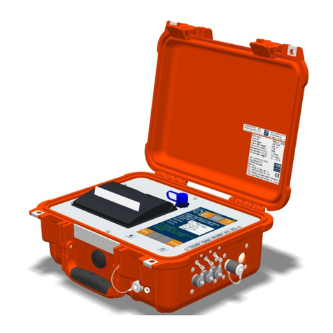
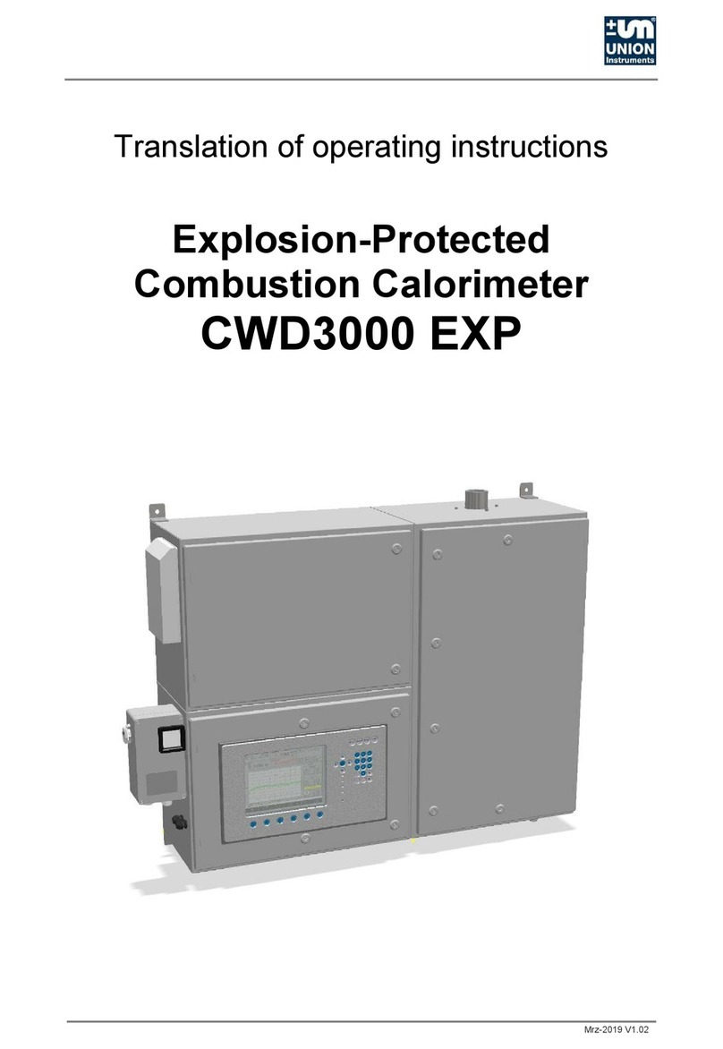
Union Instruments CWD2005 SPC User manual

Apr-2016 V1.06
Original Operating Instructions
Combustion Calorimeter
CWD2005,
CWD2005 Plus

Apr-2016 V1.06
UNION Instruments GmbH
Zeppelinstraße 42
76185 Karlsruhe
Germany
+49 (0)721-680381-0
+49 (0)721-680381-33
support@union-instruments.com
http://www.union-instruments.com
© 2016
This documentation is protected by copyright. All rights, in particular the rights of translation,
reprint, extraction of figures, radio transmission, and duplication by photomechanical or other
means and of storage in data processing systems, in whole or in part, are reserved.
Technical data subject to change.

Table of contents
3
Table of contents
Table of contents.................................................................................................................3
1Technical data ...............................................................................................................5
1.1 Dimensions...................................................................................................................5
1.2 Device overview ...........................................................................................................6
1.3 Voltage supply..............................................................................................................6
1.4 Interfaces .....................................................................................................................6
1.5 Display times of combustion value measurement.........................................................7
1.6 Gas inputs....................................................................................................................7
1.7 Calibration gas / Test gas.............................................................................................7
1.8 Process gas..................................................................................................................8
1.9 Linearity and measuring ranges....................................................................................8
1.10 Environmental conditions..............................................................................................9
2EU Declaration of Conformity.....................................................................................11
3Safety information.......................................................................................................13
3.1 Warning information and symbols...............................................................................13
3.2 Principle, intended use ...............................................................................................14
3.3 Personnel and qualification.........................................................................................14
3.4 Safety information.......................................................................................................15
3.4.1 General safety information .......................................................................................15
3.4.2 Information on specific hazards................................................................................15
3.4.3 Note on explosion protection....................................................................................16
3.5 Safety precautions on the owner side.........................................................................16
3.5.1 Recurring operator training.......................................................................................17
3.5.2 Performing a workplace hazard analysis ..................................................................17
4Protective equipment..................................................................................................19
4.1 Main switch.................................................................................................................19
4.2 Safety switch..............................................................................................................19
4.3 Thermal cutoff ............................................................................................................20
4.4 Solenoid valve............................................................................................................20
4.5 Fan.............................................................................................................................20
4.6 Door enclosure...........................................................................................................20
4.7 Markings and warning information..............................................................................21
5Description and connections......................................................................................23
5.1 Enclosure connections outside...................................................................................23
5.2 Connections and components inside..........................................................................25
5.3 Accessories................................................................................................................26
6Transport, installation, and acceptance ....................................................................27
6.1 Transport....................................................................................................................27
6.2 Environmental conditions............................................................................................28
6.2.1 Storage conditions....................................................................................................28
6.3 Installing and connecting............................................................................................29
6.3.1 Installation location...................................................................................................29
6.3.2 Room ventilation ......................................................................................................30
6.3.3 Wall mounting ..........................................................................................................31
6.3.4 Process gas .............................................................................................................33
6.3.5 Carrier gas supply....................................................................................................34
6.3.6 Calibration gas.........................................................................................................35
6.3.7 Flue gas...................................................................................................................36

Technical data
4
6.3.8 Electrical connection ................................................................................................37
6.3.9 Electrical interfaces..................................................................................................38
6.3.10 Connector assignment Input-Output IOexternal........................................................39
6.4 Commissioning after installation .................................................................................42
6.4.1 Removing/attaching transport securing devices........................................................43
6.5 Documentation ...........................................................................................................44
7Commissioning/Switching on.....................................................................................45
8Description of the work stations/operator control elements....................................47
9Operation .....................................................................................................................49
9.1 Operation of membrane keyboard/Description of display............................................49
9.2 Basic operation...........................................................................................................51
9.3 Available displays.......................................................................................................51
9.4 General information....................................................................................................52
9.5 Menu structure............................................................................................................53
9.6 Main menu .................................................................................................................54
9.6.1 Main menu - Options ...............................................................................................55
9.6.2 Main menu - Trend ..................................................................................................80
9.6.3 Main menu - Event list .............................................................................................85
9.6.4 Main menu - Device information ..............................................................................86
10 Decommissioning / Switching off...............................................................................89
11 Maintenance.................................................................................................................91
11.1 Preparations...............................................................................................................91
11.2 Maintenance work/Inspection .....................................................................................92
12 Troubleshooting..........................................................................................................95
12.1 Preparations for troubleshooting.................................................................................96
12.2 Changing/replacing fuses ...........................................................................................97
12.3 Unstable measured value...........................................................................................97
12.4 Drift of measured value...............................................................................................97
12.4.1 Incorrect ignition.......................................................................................................97
12.4.2 Error/status messages..............................................................................................98
13 Service .......................................................................................................................101
14 Disposal .....................................................................................................................103
15 Spare parts.................................................................................................................105
16 Appendix....................................................................................................................107
Data Structure Profibus......................................................................................................107
Data struture serial interface RS 232 (option) ....................................................................108
Index .................................................................................................................................109
List of figures .....................................................................................................................110
List of tables.......................................................................................................................110

Technical data
5
1 Technical data
1.1 Dimensions
Fig. 1.1: Housing dimensions
Weight: approx. 54 kg

Technical data
6
1.2 Device overview
Fig. 1.2: Markings and warning information
1. Warning information for electricity
2. Name plate
1.3 Voltage supply
Voltage:
230 Volt or 115 Volt 50/60 Hz alternating current
Power consumption:
185 VA max.
Protection class:
I
Degree of protection:
IP50
1.4 Interfaces
Interfaces:
RS232, Profibus, Fieldbus, Industr. Ethernet
Analog outputs:
3, 4 - 20 mA for heating value, Wobbe, and density
Digital outputs:
3 relays
1
2

Technical data
7
1.5 Display times of combustion value measurement1
Dead time:
3 seconds
50% time:
7 seconds
90% time:
CWD2005: 20 seconds,
CWD2005 PLUS: 15 seconds
99% time:
CWD2005: 60 seconds,
CWD2005 PLUS: 55 seconds
1.6 Gas inputs
Process gas:
1, optionally 2 for dual measuring ranges
Calibration inputs:
1, optionally 2 for dual measuring ranges
Test gas inputs:
1
Fast loop:
optional
Gas connections:
Compression fitting 6 mm
1.7 Calibration gas / Test gas
Calibration gas:
Dependent on the process gas
Calibration interval:
Dependent on the process gas
Calibration duration:
Process lasts up to 20 minutes,
gas flow approx. 10 minutes
Gas consumption:
Approx. 7 l gas per calibration (dependent on the
calibration gas)
Input pressure, max:
40 mbar
Input pressure, min.:
20 mbar, dependent on the gas
1The display times are measured from the time the new gas reaches the burner. Display times are
based on measurements with pure methane.

Technical data
8
1.8 Process gas
NOTE
The process gas must be free of condensate, dust and other contaminants, such
as naphthalene.
Gas connection inlet pressure:
20 - 40 mbar
Gas consumption:
30 - 40 l/h (min. rel. density 0.50 with 0.55 mm
nozzle)
1.9 Linearity and measuring ranges
The measuring ranges cannot be utilized from 0% to 100%. The range is depend-
ent on thegas composition. Ranges of 45-100 % are typical for a measuring range.
Hydrogen content in the gas increases the measuring range span. Inert gases such
as N2, O2, or CO2, reduce the measuring range span.
CWD device
series
CWD2005
CWD2005
CT
CWD2005
PLUS
CWD2005
DPC
CWD2005
SPC
CWD2000
Ex
Flare gas 0 – 15 3.0 –– –– –– –– 0 – 15 0 – 15 –– ––
Blast furnace
gas
3.5 – 6 3.0 –– –– 3.5 – 6 3.0 3.5 – 6 3.0 3.5 – 6 3.0 –– ––
Converter gas 4.5 – 9 1.5 –– –– –– –– 4.5 – 9 1.5 4.5 – 9 1.5 –– ––
Mixed gas 5 – 10 2.0 –– –– 5 – 10 2.0 5 – 10 2.0 5 – 10 2.0 –– ––
Coke oven gas 15 – 30 1.5 –– –– 15 – 30 1.5 15 – 30 1.5 15 – 30 1.5 –– ––
Biogas 25 – 35 1.5 –– –– 25 – 35 1.5 25 – 35 1.5 25 – 35 1.5 –– ––
Natural gas 25 – 48 1.5 30 – 47 1.0 25 – 48 1.0 25 – 48 1.0 25 – 48 1.0 25 – 47 1.0
Refinery gas 25 – 50 1.5 –– –– 25 – 50 1.5 25 – 50 1.5 25 – 50 1.5 –– ––
Liquefied petro-
leum gas (LPG)
40 - 90 1.5 –– –– 40 - 90 1.5 40 - 90 1.5 40 - 90 1.5 –– ––
2.0 2.0
Measuring range [MJ/m] / Accuracy [± MBE]

Technical data
9
1.10 Environmental conditions
NOTICE
When the combustion calorimeter is used outside of the environmental
conditions, additional measures (air conditioning of the combustion calorimeter,
etc.) must be agreed on with UNION Instruments GmbH!
Installation location:
Installation room required (
Chapter 4)
Room temperature:
5 – 40 °C
Temperature change
≤ 5 °C per hour
Air humidity:
0 – 95 % rel. humidity
Ambient pressure:
800 – 1100 hPa (0.8 – 1.1 bar)

Technical data
10

EU Declaration of Conformity
11
2 EU Declaration of Conformity
Der Hersteller / The manufacturer UNION Instruments GmbH
Zeppelinstraße 42
76185 Karlsruhe
erklärt hiermit, dass folgend bezeichnete Produkte / hereby declares, that following named products:
Produktbezeichnung: Verbrennungskalorimeter Gerätegruppe: CWD2005
Product name: Calorimeter device group: CWD2005
konform sind mit den Anforderungen, die in der EU – Richtlinie festgelegt sind / are compliant with the require-
ments as defined in the EU directive:
2014/30/EU Elektromagnetische Verträglichkeit
2014/30/EU Electromagnetic compatibility
2014/35/EU Elektrische Betriebsmittel zur Verwendung innerhalb bestimmter Spannungsgrenzen
2014/35/EU electrical equipment designed for use within certain voltage limits
Angewandte harmonisierte Normen / Used harmonized standards:
EN 61010-1:2010 Sicherheitsbestimmungen für elektrische Mess-, Steuer-, Regel- und Laborge-
räte - Teil 1: Allgemeine Anforderungen
Safety requirements for electrical equipment for measurement, control, and
laboratory use - Part 1: General requirements
EN 61326-1:2013 Elektrische Mess-, Steuer-, Regel- und Laborgeräte - EMV-Anforderungen -
Teil 1: Allgemeine Anforderungen
Electrical equipment for measurement, control and laboratory use - EMC re-
quirements - Part 1: General requirements
Name des Dokumentationsbevollmächtigten: Schlichter
Name delegate of documentation
Adresse des Dokumentationsbevollmächtigten: siehe Adresse des Herstellers
address delegate of documentation see address of manufacturer
Bei einer nicht autorisierten Änderung des Gerätes verliert diese Erklärung ihre Gültigkeit. / Any unauthorized mo-
dification of the device results in invalidity of this declaration.

EU Declaration of Conformity
12

Safety information
13
3 Safety information
3.1 Warning information and symbols
The operating instructions use the following nomenclature and symbols for espe-
cially important information:
DANGER
For an immediate danger that can lead to serious physical injury or death!
WARNING
For a potentially dangerous situation that can lead to serious physical injury or
death!
NOTICE
For a potentially dangerous situation that can lead to minor physical injury! This
may also be used for warnings of property damage!
NOTE
For information that can improve the operation of the combustion calorimeter or
contribute to prevention of property damage.

Safety information
14
3.2 Principle, intended use
WARNING
Intended use also includes observance of these operating instructions! In addi-
tion to the following safety information, the safety information of linked system
components must also be observed!
Additional equipment or accessory parts not installed, supplied, or made by
UNION Instruments GmbH require manufacturer's approval by UNION Instru-
ments GmbH! Any warranty is otherwise voided!
The combustion calorimeter is a digitally controlled calorimeter. It measures ac-
cording to the dry measurement principle. The heat is transferred from the burner
to the measuring elements through air.
The combustion calorimeter is a sensor system for determining the combustion
value of different process gases. The analysis serves the process control.
The combustion calorimeter is intended for use in weather-proof areas and for fixed
mounting and installation.
The combustion calorimeter is not suitable for operation in hazardous areas.
In the case of toxic or explosive gases, the safety provisions applicable at the in-
stallation location must be complied with.
Any use beyond this is regarded as intended use. The manufacturer is not liable
for damage resulting from this. In this case, the risk is borne solely by the installa-
tion engineer/commissioning engineer/owner/operator.
Only skilled persons are permitted to make changes to the combustion calorimeter
(mechanical/electrical/pneumatic changes).
3.3 Personnel and qualification
Gas connections and work on the electrical equipment of the combustion calorim-
eter may only be carried out by a skilled person in compliance with safety provi-
sions, especially for hazardous areas.

Safety information
15
3.4 Safety information
3.4.1 General safety information
WARNING
Only operate the combustion calorimeter when all protective equipment is pre-
sent and operational!
Further safety information:
Before the corresponding chapters!
3.4.2 Information on specific hazards
DANGER
•After installation, all gas-conveying parts must be checked for leak tightness
according to national regulations.
•Any type of repair that requires opening of the protective cover may only be
carried out by instructed qualified personnel!

Safety information
16
3.4.3 Note on explosion protection
NOTE
The operation/installation of a UNION combustion calorimeter does not produce
a hazardous area because combustible gas does not escape from the calorime-
ter and form an explosive atmosphere.
No combustible gas escapes from the UNION combustion calorimeter because:
•in conformity with the intended use of the combustion calorimeter, the gas is
combusted in the device,
•the gas supply in the device is shut off as soon as the flame in the burner
goes out or if the fan fails, and
•the gas-conveying lines can be regarded as technically leak-proof on a con-
tinuing basis (compression fittings) or through a systematically recurring
testing of tubes and membranes described in the operating instructions.
All gas inputs in the combustion calorimeter are provided with solenoid valves.
The solenoid valves close automatically in the event of a fault during combus-
tion or ignition of the gas mixture.
The solenoid valves are closed in current-free state.
3.5 Safety precautions on the owner side
WARNING
•The owner must provide suitable protective equipment for the combustion
calorimeter that can reliably prevent injuries to personnel, e.g., from escap-
ing gas.
•Exhaust discharged process gas to a safe environment!
•Tripping hazard from improperly routed supply lines!
Other owner-side safety precautions
corresponding chapter!

Safety information
17
3.5.1 Recurring operator training
NOTE
Country-specific regulations regarding recurring training of operators must be
observed by the owner, particularly with regard to the handling of hazardous ar-
eas, gases, and electrical equipment.
3.5.2 Performing a workplace hazard analysis
NOTE
Depending on the national regulations and, if necessary, independent of the CE
marking of this combustion calorimeter, the owner must prepare a workplace
hazard analysis and specify personal safety equipment for different phases of
operation.
Deviations from these operating instructions may occur due to further technical
developments. If you desire additional information or if specific problems arise that
are not covered in detail in this manual, you will receive information by contacting
the following address:
UNION Instruments GmbH
Zeppelinstraße 42
76185 Karlsruhe
Germany
+49 (0)721-680381-0
+49 (0)721-680381-33
support@union-instruments.com
http://www.union-instruments.com

Safety information
18

Protective equipment
19
4 Protective equipment
4.1 Main switch
Fig. 4.1: Main switch (example)
4.2 Safety switch
The safety switch disconnects the ignition transformer from the voltage supply
when the upper door is opened.
Fig. 4.2: Figure Safety switch (example)

Protective equipment
20
4.3 Thermal cutoff
NOTE
The tripping temperature of the thermal cutoff is 72 °C.
When tripped, the thermal cutoff disconnects the 24 V voltage supply of the sole-
noid valves.
4.4 Solenoid valve
In the event of malfunctions, the solenoid valves of the combustion calorimeter
close automatically. A restart of the combustion calorimeter is necessary.
4.5 Fan
The fan mixes exhaust gases produced during combustion with fresh air and en-
sures an appropriate volume flow. The fan is speed-monitored. If the fan fails, the
combustion calorimeter goes to a safe state.
4.6 Door enclosure
Protective covers of the housing separate electrical components and hot surfaces
of the environment.
Other manuals for CWD2005 SPC
1
This manual suits for next models
1
Table of contents
Other Union Instruments Measuring Instrument manuals

Union Instruments
Union Instruments CWD2000 EX User manual

Union Instruments
Union Instruments INCA6002 Quick guide

Union Instruments
Union Instruments INCA6003 Quick guide

Union Instruments
Union Instruments INCA5021 Quick guide

Union Instruments
Union Instruments INCA5051 Quick guide

Union Instruments
Union Instruments PMS3000 Quick guide

Union Instruments
Union Instruments INCA Series User manual

Union Instruments
Union Instruments INCA4003 Quick guide

Union Instruments
Union Instruments INCA6004 Quick guide

Union Instruments
Union Instruments INCA5011 Quick guide