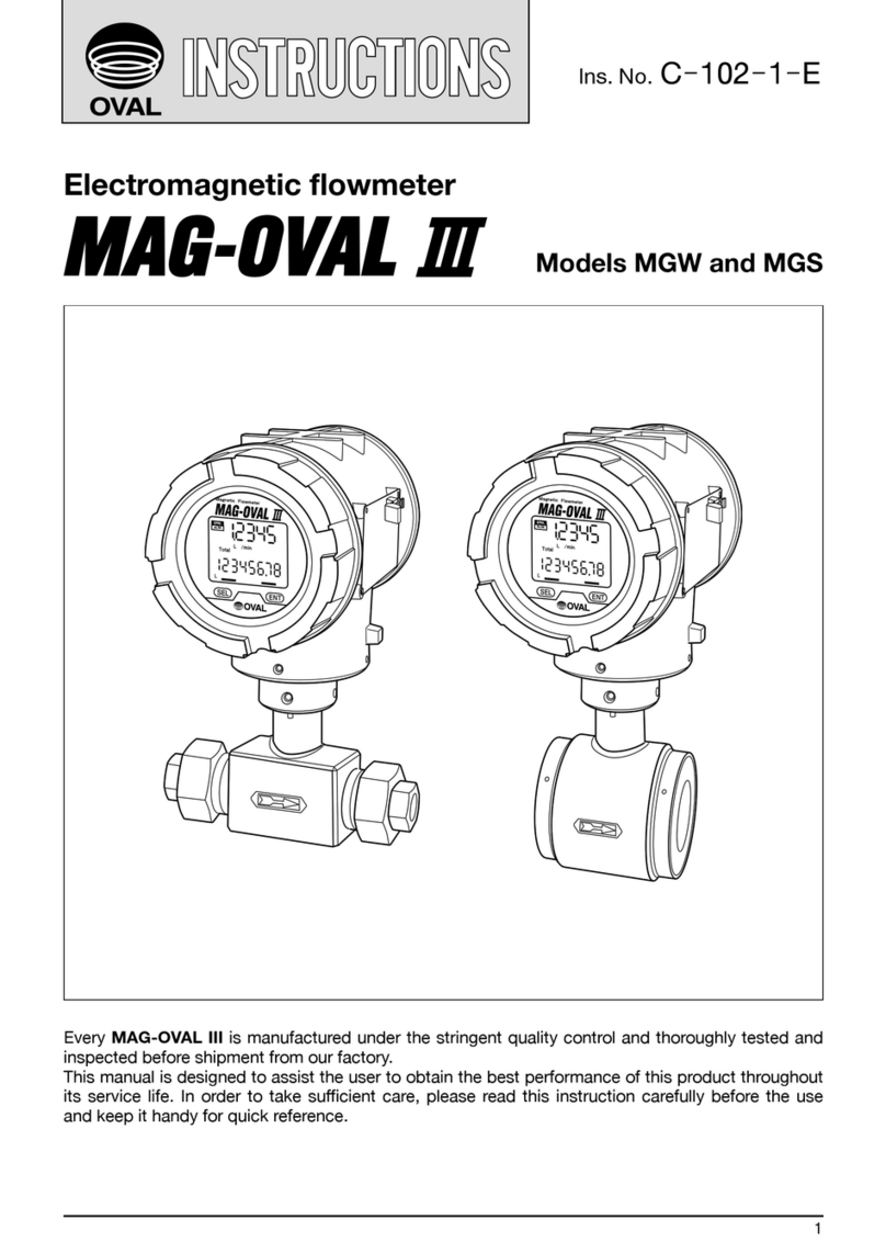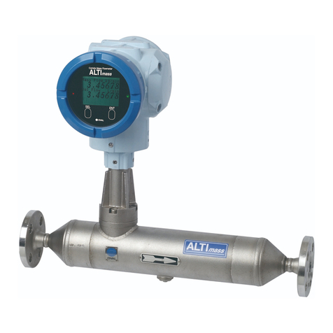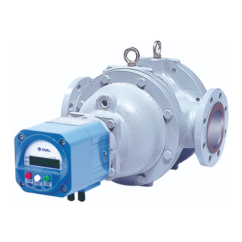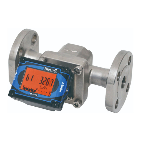
CONTENTS
1. BEFORE YOU BEGIN .............................................................................................. 4
1.1 Conrming the Nameplate .............................................................................................................4
1.2 Transportation Considerations .......................................................................................................4
1.3 Storage Considerations .................................................................................................................4
1.4 Structural Considerations ..............................................................................................................5
2. OPERATING CONDITIONS...................................................................................... 5
2.1 Operating Conditions for Explosionproof Model ...........................................................................6
3. GENERAL ................................................................................................................ 7
4. PART NAMES .......................................................................................................... 8
5. LCD COUNTER DISPLAY........................................................................................ 8
5.1 Register Model UA .........................................................................................................................8
5.1.1 About "MODE" Switch .............................................................................................................8
5.1.2 About the Displayed Messages during Operation ...................................................................9
5.1.3 About "RESET" Switch ............................................................................................................9
5.2 Register Model U8 .......................................................................................................................10
5.2.1 About "MODE" Switch ...........................................................................................................10
5.2.2 Display Functions...................................................................................................................10
5.2.3 Display Selection....................................................................................................................10
5.2.4 Total Flow Reset.....................................................................................................................11
5.2.5 Precautions for Pulse Output Type ........................................................................................11
6. INSTALLATION ...................................................................................................... 12
6.1 Considerations on Installation......................................................................................................12
6.2 Standard Installation, Horizontal Line ..........................................................................................12
6.3 Standard Installation, Vertical Line...............................................................................................12
6.4 Example of Faulty Piping .............................................................................................................12
7. HOW TO CHANGE FLOW DIRECTIONS............................................................... 13
8. WIRING INSTRUCTIONS ...................................................................................... 14
8.1 Wiring Connections at Terminals..................................................................................................14
8.2 Terminal Connections...................................................................................................................14
8.3 Wiring Connections of Register Model UA ..................................................................................15
8.4 About Load Resistance Range, Register Model UA (current pulse and analog output)....................... 15
8.5 Preamp-to-Receiving Instrument Hookup with Register Type U8 ...............................................16
9. OPERATING INSTRUCTIONS ............................................................................... 17
9.1 Flushing the Piping Assembly......................................................................................................17
9.2 Operating Considerations ............................................................................................................17
9.3 Precautions for Models without Battery Pack..............................................................................18
9.4 About the Register Life ................................................................................................................18
10. DISASSEMBLY AND INSPECTION ..................................................................... 19
10.1 Disassembly and Inspection Procedures...................................................................................19
10.2 Assembly....................................................................................................................................21
10.3 Disassembly and Inspection as Installed in the Piping Assembly .............................................21
10.4 Reconditioning the Rotor Gear Teeth.........................................................................................22
10.5 Signal Generating Magnet Disassembly and Reassembly Notes..............................................22
11. UA REGISTER SWITCH FUNCTIONS AND PARAMETER SETUP...................... 23
11.1 Switch Names and Functions ....................................................................................................23
11.1.1 Function Setup Switch "SW2" .............................................................................................24
●
●
CAUTION: lmarked sections apply to
Smart type (register type: U8)

