Unipro 6002 User manual

Quick Guide
Unipro Laptimer
6002 / 7002
Version 1.32
Go faster faster
UNIPRO ApS
VIBORG HOVEDVEJ 24
DK-7100 VEJLE
DENMARK
Tel.: +45 75 85 11 82
Fax: +45 75 85 17 82
www.uniprolaptimer.com

Introduction.............................................................................................................................3
Get ready to go!......................................................................................................................4
Do you have the necessary accessories?...........................................................................................4
Installation............................................................................................................................................5
Display unit ............................................................................................................... 5
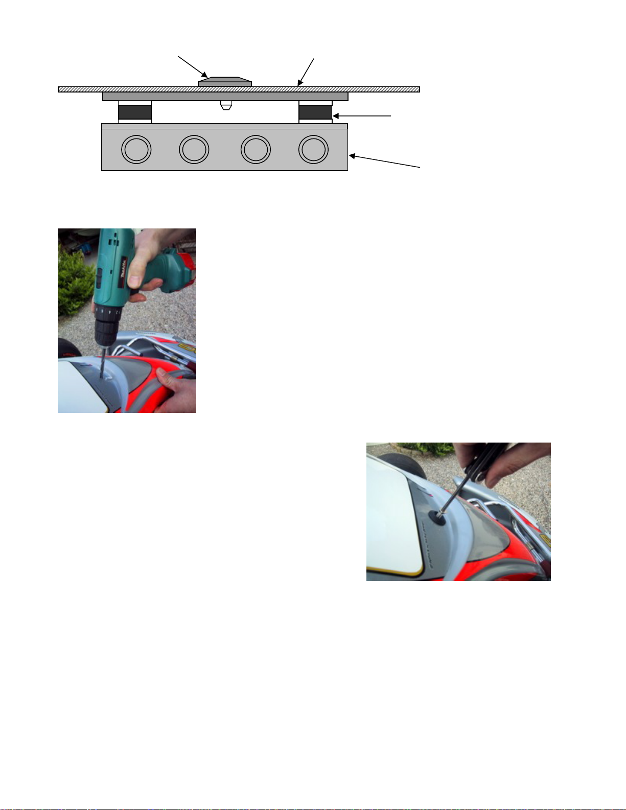
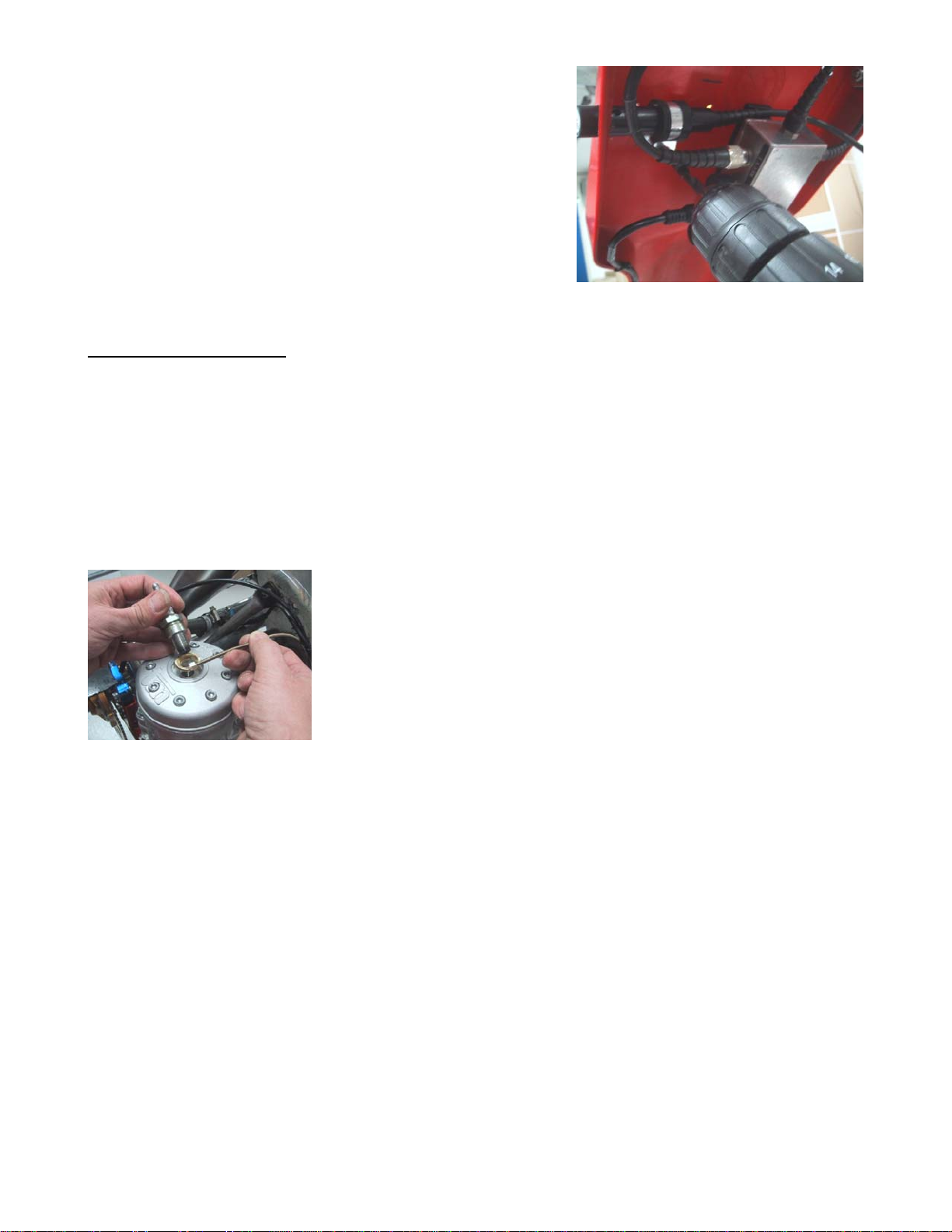
Main box ................................................................................................................... 5
RPM sensor................................................................................................................ 8
Receivers .................................................................................................................. 8
AMB Loop receiver ..................................................................................................................................... 8
Magnet receiver......................................................................................................................................... 9
Infrared receiver........................................................................................................................................ 9
Temperature sensors .................................................................................................10
Cylinder head sensor.................................................................................................................................10
Exhaust sensor .........................................................................................................................................10
Water sensor............................................................................................................................................11
Wheel sensor kit........................................................................................................12
The sensor disc.........................................................................................................................................12
The wheel sensor ......................................................................................................................................13
Basic functions and setup..................................................................................................................15
Display buttons .........................................................................................................15
Receiver type ...........................................................................................................................................16
Stripe setup .............................................................................................................................................16
Magnet count ...........................................................................................................................................17
Magnet delay............................................................................................................................................17
More settings............................................................................................................................................17
Practice and race using the basic functions......................................................................18
Operating modes...............................................................................................................................18
First lap mode...........................................................................................................18
Running mode...........................................................................................................19
Pit mode ..................................................................................................................19
Clear all laps.............................................................................................................20
Take advantage of the advanced features..........................................................................20
Split times / Split points......................................................................................................................20
Splits with magnet stripes...........................................................................................20
Defining the split points with magnet stripes ................................................................................................21
Undo Clear split points!..............................................................................................................................21
Splits with wheel sensor .............................................................................................21
Defining the split points with the use of the wheel sensor...............................................................................22
Typical track with 6 split points...................................................................................................................23
Measure and set the wheel circumference ....................................................................................................23
Temperature sensors.........................................................................................................................24
Setup the temperature inputs......................................................................................24
Temperature warning points........................................................................................24
Analyse your data..............................................................................................................................25
Data Analyser ...........................................................................................................25
PC Analyser ..............................................................................................................26
Receive data from the Laptimer ..................................................................................................................26
UNIPRO – The original Laptimer 2

Introduction
Thank you for trusting us to deliver the most advanced Laptimer on the market.
The Unipro Laptimer has several unique features and will measure every piece of information with
a speed and accuracy you have only dreamt about! It really enables you to use your Laptimer as a
tool to go faster, faster.
We did all we could to make your investment as future proof as possible and you should be able to
enjoy it in many years to come. With the unique possibility to expand it later, with accessories like
G-force sensor, telemetry, tire temperatures and more, your investment is even safer.
If you have a special request either for new accessories or for a new feature, please let us know.
We constantly try to develop our products with the most useful features so you can use the
Laptimer to go faster, faster but we always appreciate good ideas from the users of our products.
If you have any problems or questions regarding your Unipro Laptimer we will make sure to give
you the necessary support.
Please e-mail your questions to support@uniprolaptimer.com or contact your local dealer.
Good luck on the tracks!
UNIPRO ApS
Viborg Hovedvej 24
DK-7100 Vejle
Denmark
Web: www.uniprolaptimer.com
E-mail: [email protected]
UNIPRO – The original Laptimer 3

Get ready to go!
In this chapter, we will give you the most necessary information about what to do before you can
start using your Laptimer. If you are an experienced user, looking for exact information, you may
want to jump to the reference manual.
Do you have the necessary accessories?
If you have bought the basic package you should have following parts to your Laptimer:
Main Box Display Unit Receiver – Loop, Magnet or IR
RPM Sensor
You may also have bought any of these extra accessories:
Cylinder Head Sensor Water Sensor T-Junction
Exhaust Sensor Kit Speed Kit USB Cable
The Unipro Laptimer can work with three different temperature sensors at the same time.
UNIPRO – The original Laptimer 4

UNIPRO – The original Laptimer 5
Installation
Your Laptimer is a precision instrument and you should take the necessary time to ensure correct
installation. A basic rule is to start from the sensors and go back to the Laptimer, never the other
way. If cables are too long, they should always be looped at the end near the Laptimer. Use
plenty of strips to fix the cables to the frame.
DISPLAY UNIT
The Display Unit is mounted on the steering wheel. Due to the ultra thin Display Unit, you will not
have any problems with regulations.
Figure 1. Display unit mounted on steering wheel
First, the Display Unit is mounted on the steering
wheel. Choose a hole that gives a good placement at the
top of the steering wheel. On some steering wheels, it is
necessary to make the hole a little bigger.
Remove the nut, the gray washer and one of the two
black rubber washers. These parts are mounted on the
back side of the steering wheel, as shown in figure 1.
It is important to keep the right order of the washers.
Please follow this sequence:
Nut – metal washer – gray plastic washer – black rubber
washer – steering wheel – black rubber washer – Display
Unit.
Tighten the nut when the display is strait and centered in the
steering wheel. This picture shows the correct mounted
Display Unit.
MAIN BOX
Nut
The main box is mounted behind the front cover. The following
and its components.
picture is showing the main box
Gray washer
Metal washer
Rubber washer Steerin
g
wheel
Rubber washer
Display unit

The main Box is mounted be ont cover.
First, a 6.5 mm hole is drilled in e karts have a
recess in the coat suitable for drilling the hole in. If you press hard
on the sticker, you can see where to drill the hole. It is a good
idea to look from the back before drilling!
w
The enclosed screw is screwed throug
ease the mounting of the main box. Use a 5 mm
umbracho.
Figure 2. Main Box with fittings
hind the fr
the cover. Som
Use the enclosed umbracho scre
h the front coat to
Screw with washer Front cover
Vibration dam
p
er
Main box
UNIPRO – The original Laptimer 6

Make sure that the cable for t e Display Unit is pointing
upwards.
The Main Box is held with one hand and the umbracho screw is
tightened with the other hand. The cable for the Display Unit must
be pointing upwards. Make sure the box i ht before
tighten the screw hard.
The picture shows the Main Box after it is correctly mounted
behind the front cover. With the Display U Main Box
correctly mounted, you connect the Main Box and the Display
Unit, and start to install the different sensors.
The cable for the Display Un
Main Box, along the steering
the Display Unit. Tighten the
use your fingers.
Make sure the cable isn’t squeezed.
It is very important that the cable cannot be squeezed,
even at full swing of the steering wheel. Make a loop on
e cable and st wheel all the way to both sides and
ble at any points feels tight.
h
s placed straig
nit and the
Cable from the Main Box to the Display Unit.
it is now routed from the
column, to the connector on
connector hard, but only
th
turning the steering
feel if the ca
rip it to the steering column. Test by
UNIPRO – The original Laptimer 7

RPM SENSOR
The RPM sensor comes stand ure
the best possible signal from
fall of during a race. If that h l
no longer be able to see you
le,
The ignition on a gokart is the worst source of electrical
noise and it is therefore a good idea to keep the RPM cable
ignition cable.
cable touch the cylinder or the
tear the isolation and shield
and cause disturbance. The most important issue is to
separate the RPM cable from the ignition cable just after
the sensor. This is clearly shown on the picture. Do not let
the two cables run together!
The cable is mounted in the connector marked RPM on the main box. Tighten the connector
hard with your fingers.
RECEIVERS
ard with every Unipro Laptimer. We use an active sensor to ens
all kind of engines. Mount the sensor with care. You do not want it to
appens, the Laptimer will turn itself off after 5 minutes and you wil
r lap times.
Mount the sensor with at least two strips.
The RPM sensor is mounted at the end of the ignition cab
near the spark plug cap, with at least two strips.
away from the
Please do not let the RPM
cylinder head because it can
The Unipro Laptimer supports all kind t
things. If the track has a loop, we rec
AMB Loop receiver
Mounting the Loop receiver.
The Loop receiver is mounted as low as possible on the left
side of the seat. Drill a 6.5 mm hole from the inside of the
seat. The distance from the underside of the Loop receiver to
the asphalt must not exceed 100 mm
of receivers. The different receivers are good for differen
ommend using the Loop Receiver.
.
The Loop receiver is mounted parallel with the seat and needs
to point backwards against the rear axle. Make sure, that
nothing comes between the receiver and the track.
Use plenty of strips to secure the cable to the Main Box.
When the receiver is mounted, the cable is fixed to the middle of the kart, all the way to the
Main Box. Use plenty of strips to secure the cable.
The cable is mounted in the connector named RECV 1 on the Laptimer. Tighten the connector
hard with your fingers.
UNIPRO – The original Laptimer 8

se on the bottom plate. Measure and drill the
hole from the backside. The most important issue is to
ost
forward.
d
Lead the cable up on the back side
Main Box. It is important that the c
recommend that you use strips to fi
onnector marked RECV 1 on the
ceiver. the
he
Remember to place the infrared transmitter at the same
Magnet receiver
Mounting the magnet receiver.
The best place to mount the magnet receiver is
lengthwi
minimize the vibrations to the receiver. The m
common placement of the magnet receiver is at the
very front of the bottom plate, with the cable facing
The distance between the receiver and asphalt must
not exceed 50 mm.
Make sure that the cable is fixe properly.
of the front cover and into the
able is fixed properly. We
x the cable to the front cover.
The cable is mounted in the c
Main Box. Tighten the connector hard with your fingers.
Infrared receiver
Mounting the Infrared re
The best place to mount the infrared receiver is behind
front cover. Measure and drill the hole from the side. T
most important issue is to mount the receiver horizontal.
height as the infrared receiver at least 3 meters from the
track.
UNIPRO – The original Laptimer 9

Make sure that the cable is fixed properly.
Lead the cable up on the back side of the front cover and
x. It is important that the cable is fixed
e
to the front cover.
The cable is mounted in the connector
the Main Box. Tighten the connector ha
TEMPERATURE SENSORS
into the Main Bo strips to fix the cableproperly. We recommend that you us
marked RECV 2 on
rd with your fingers.
possible to use up to three temperature sensors. Two of them (Temp 1 +
) are using a standard which is limited in the temperature range, but has a very high precision.
or and water sensor. The last input (Temp 3) is
d for the exhaust sensor.
his is the cylinder head or plug sensor. There are different types, depending on your engine type.
r 2 input.
Remove the washer on your spark plug before mounting
The ring for the sensor is mounted between the cylinder head and
the spark plug. Use plenty of strips to secure the cable from the
cylinder head to the Main Box. You may need different types if
you use different engines. Ask you dealer or contact Unipro if you
are in doubt.
Mount the cable in the connector marked TEMP 1 or TEMP 2 on
the Main th your fingers.
Exhaust sensor
The exhaust sensor is used to measure the temperature of the exhaust gas from the engine. It is
important to mount it correctly, at the
the piston, you will measure temperat
input for the exhaust sensor!
On the 6002/7002 it is
2
These inputs are used for the cylinder head sens
able to measure very high temperatures, and can therefore be use
Cylinder head sensor
T
The cylinder head sensor must be use with the temperature 1 o
Box. Tighten the connector hard wi
right position. If you mount the sensor to far away from
ure of the flame instead of the gas! Use only the TEMP 3
UNIPRO – The original Laptimer 10

Weld the bush on
12-15 cm from the piston.
The bush is mounted on the
pipe. The distance should be 12-
the exhaust pipe
exhaust
15 cm
from the backside of the piston. Do not
drill a hole in the exhaust pipe before
he pipe.
After the bush is welded on the
exhaust pipe, drill a 4.1 mm hole in the
middle of the bush through the exhaust
pipe. Be careful not to damage the pipe
on the other side when you drill
pushed all the way in and tightened.
Fix the cable to the seat, and all the
T
n
T
f
ater sensor
This is the sensor for measuring the water heat. Use either TEMP 1 or TEMP 2 for the water
u drive a kart with water cooled engine, the heat of the cooling water is of course
The water sensor is mounted on the hose that goes from
the cooler to the engine. It is best to mount the sensor
on the hose so the sensor sits near the seat, pointing
downwards.
Cut the hose in the right place and remember to put the
two hose clamps on the two ends of the hose before
inserting the T-junction in the hose.
you have welded the bush on t
through the pipe.
Mount the sensor in the bush.
After the hole is drilled, the sensor is
way to the Main Box, so it is well
protected.
he cable is mounted in the connector
amed TEMP 3 on the Main Box.
ighten the connector hard with your
ingers.
W
sensor. When yo
important for the performance of the engine.
Mounting the water sensor.
UNIPRO – The original Laptimer 11

Tighten the two hose clamps
to secure the T-junctio
n in the
strips to the frame and lead it
.
e connector hard
with your fingers.
WHEEL SENSOR KIT
right place.
Mount the cable on the sensor
and tighten it hard with your
fingers. Then fix the cable with
all the way to the Main Box.
Mount the cable in the
connector marked TEMP 1 or
TEMP 2 on the Main Box
Tighten th
The wheel sensor kit is used the Laptimer. For instance
speed, splits, tire wear count
The sensor disc
The sensor disc is mounted o ost of the corners on the
track. On most tracks this wi lways best to count the corners of
the track, and then choose th
Dismount the wheel and put the centering bush in the
inner ring of the bearing.
for many of the advanced features in
ers, lap length and more.
n the front wheel with pressure on in m
ll be the left front wheel. But it is a
e appropriate wheel.
UNIPRO – The original Laptimer 12

The sensor disc is
placed over the
centering bu
sh and it
held firmly down.
crews hard, so the
nsor disc is mounted, the
centering bush is removed again. The ng again.
he wheel sensor
The sensor fitting is mounted in a suitable hole in the
stub axle. Depending on the kart model, it can be
If you mount the fitting so the edge is 35-40 mm from
the sensor disc, you will be able to make some
e di
the sensor and the sensor disc is between 3 and 10
millimeters.
If you experience problems with the speed, this distance
is the first thing to check!
is
Then tighten the
three small screws
that fixes the sensor
disc to the wheel.
Tighten the three
s
u’re driving. After the se
wheel is now ready for mounti
sensor disc doesn’t go loose when yo
T
necessary to drill a hole in the stub axle.
adjustment on the sensor without having to move the
fitting.
Mount the sensor in the fitting so th stance between
UNIPRO – The original Laptimer 13

with your fingers.
The cable is fixed to
the wheel can tu
tightened.
Remember to make t
adjustment of the
width of the kart.
Fix the cable to the
Main Box. The cabl
WHEEL on the Main
the frame in a nice large curve so
rn without the cable being caught or
he loop large enough to allow
sensor when you change the front
frame with strips all the way to the
e is mounted in the connector named
Box Tighten the connector hard
.
UNIPRO – The original Laptimer 14

Basic functions and setup
We have put a lot of experience and e aking the Display Unit very easy to operate on
the track and in the pit. The feed bac ptimer
tells us that we have succeeded. Here splay
Unit.
DISPLAY BUTTONS
ffort into m
k we get from drivers and teams using the Unipro La
you can get an overview over the functions on the Di
SPLIT
Change between
splits and enter split
measure mode with
long press.
Enter UNDO mode
by holding it down at
power-on.
SETUP
Used for entering
setup and service
mode.
Changes between
min/max values in
pit mode
Temp 1
warning
All the LEDs can
be used as shift
light indicators.
Temp 3
warning Temp 2
warning
Infrared
communi-
cation
IrDA
UPPER DISPLAY
LOWER DISPLAY
FUNCTION
Enter Time Run Mode.
Change values in upper
display. Clear laps and
more.
MODE
Press once to turn
the Laptimer on.
Hold it down to turn
it off. Change
between different
modes.
DOWN
Adjust different
values DOWN. Hold
it down to increase
the speed of the
UP
Adjust different
values UP. Hold it
down to increase the
speed of the
adjustment.
adjustment.
UNIPRO – The original Laptimer 15

BASIC SETUP hat the basic settings match your actual setup. You enter
3. Press SETUP again to browse through the different setup screens
ou can read about all the setup screens in the reference manual. Here we will introduce you to
e ones you need to know to get started.
e
he receiver type screen.
ro Laptimer can use all types of
choose between IR (infrared), Loop (AMB
Stripe (magnets).
Use the
Go to setup mode, and make sure t
setup mode this way:
1. Press MODE to turn on the Laptimer
2. Press SETUP to enter setup mode
Y
th
R ceiver type
This is t
The Unip receivers. You can
active loop) and
and but choose the receiver type
connected to the Laptimer. I se a loop receiver, you
can skip the explanation about stripe setup!
tripe setup
This is the stripe setup screen.
If the receiver type is set to Stripe (magnets) this is the next
step. It is the most important setup before you start driving
on a new track. You need to set two values. The number of
magnets from the pit to the finish line (2 in this example)
and the total number of magnets on the track (3 in this
example).
ress
tons to
f you u
S
to set the two values (see the next two screens and the example with a typical
P
track).
UNIPRO – The original Laptimer 16

Magnet count
Set the total number of magnets on the track.
When you press from the stripe setup screen, you can
al number of magnets on the track. You can
etween 1 and 8 magnets. If you don’t know the
timer to use only
one magnet and then drive one lap. Then you can see how
edit the tot
choose b
number of magnets, you can set the Lap
many times the Laptimer triggers.
Use the and buttons to adjust the total number of magnets.
n
When the correct number of mag ets is entered, press to edit the number of magnets
the next screen).
from the pit to the finish line (See
Magnet delay
ish
line.
This is the number of magnets you need to delay when going
s example, you need to
Set the number of magnets from the pit to the fin
from the Pit to the finish line. In thi
pass two magnets when going out from the Pit. This means,
that on the out lap (or first lap) the Laptimer ignores the first
two magnets and then start the Laptimer when passing the
third one.
Use the and buttons to agnets delay.
adjust the m
Press to save and return to the stripe setup screen.
More settings
If you want to get the full benefit of your Laptimer, we recommend that you use some of the more
advanced features and accessories. The most used accessories are:
•Temperature sensors for cylinder head, exhaust and / or water
•Speed kit, which enables you to use split times and speed
•Data Analyser and PC Analyser to view and analyse your data
We will get back to this later in the Quick Guide, and you can read all about it in the Reference
Manual. With the settings mentioned above, you can start to use your Laptimer, getting precise
lap times and RPM values.
UNIPRO – The original Laptimer 17

Practice and race using the basic functions
e
have already told you about the s e th ed
to know these three modes:
•First lap mode – the Laptim
•Running mode – the Laptim
•Pit mode – Enter pit mode unning mode
ding form asic functions of your
aptimer in practice and race. When you are familiar with these functions we recommend that you
– th e
FIRST LAP MODE
Now you can start using your Laptimer. The Laptimer have some different operating modes. W
etup mode. To us e basic functions of the Laptimer, you ne
er always starts in this mode
er shifts to running mode when passing the finish line
by pressing MODE from First lap or R
After rea the in ation about the three modes, you can use the b
L
start to take advantage of the more advanced functions ese will really help you to improv
your lap times.
Operating modes
is turned on with the
When the Laptimer button, it
,
timer will automatically
ange to first lap mode when it detects a signal from the RPM sensor. This way, you cannot
drive around in pit mode, and think you are getting lap times. It is however possible to change
pit
lling how many magnets you need to pass before the finish line. This is the so-
Wh p to running mode.
starts up in first lap mode. This is the part of the race going
from the pit to the finish line for the first time.
It will always start from the last lap shown in the Laptimer
so you will never “overwrite” anything when turning the
Laptimer on.
If you are not in first lap mode when the engine is started, the Lap
ch
back to mode when the engine is running!
The “-2-“ is te
called stripe delay. It is possible to manual adjust this delay in first lap mode. If driving with
Loop or IR receiver, this part of the display is blank.
en assing the finish line for the first time, the Laptimer change
UNIPRO – The original Laptimer 18

RUNNING MODE
The Laptimer will automatically turn to running mode when you pass the finish line.
When the finish line is passed for the first time, the display
shows 0:00:00 to indicate that the timer is started.
the
show
hich data
All data are updated in the display every 0.5 seconds. In
display set-up you can define which values you want to
in the lower part during the race. You can choose w
to show in the upper display with the button.
The upper part of the display will always show one of the data not shown in the lower display, la
number and lap p
time. Small icons will help you identify the value shown. Indication of the best lap
is done with the BEST icon above the lap time.
urrent lap time and best lap time (Delta time) / High value
When the Laptimer is passing the finish line, it is showing the
difference between the current lap and the best lap and its
nt la
shown for 5
conds before changing back to data display.
h.
You can also turn both features of
Difference between c
position. In the shown example, the curre p is 8.98
seconds better than the previous best lap and the current lap
is the best lap (in position 1) This information is
se
It is possible to turn this feature off in service mode, where
ighest values for the current lap instead of the delta time
f.
you can also choose to show the
PIT MODE
Pit mode is for analysing the data stored in the Laptimer.
Press from either first lap mode or running mode to
ode, the Laptimer jumps to the best lap.
In this example, the best lap is lap #18. From this point, you
enter pit mode.
When entering pit m
can go two ways: If you press you will go to the next
p (19 in this example). If you press the
la button, the Laptimer jumps to lap # 1.
The BEST LAPTIME icon at the top indicates the best lap time. The button changes the
data shown in the upper display. changes between the high (maximum) and the low
(minimum) data values stored.
UNIPRO – The original Laptimer 19

CLEAR ALL LAPS
Clearing all laps and data in the Laptimer is easy!
Pressing and holding the button for two seconds, clears
all the data stored in the Laptimer. You have to confirm it
by
pressing the button again.
If you clear all laps by accident, you can use UNDO mode to
undo it again!
er starts in firstlap mode ready to drive again.
After doing clear laps, the Laptim
fore you clear the laps. Please remember, that
e logged data can only be transferred to a PC, and not to the Data Analyser.
Take advantage of the
When you are familiar with the ba
Laptimer to improve your lap time
The most important of the advanc
•Split times / Split points
•Data Analyser and PC Analyser
ain you how to use these features in this chapter.
Split times / Split points
Dividing the track into smaller sec e most important features of the Laptimer. It
will enable you to see all data in the Laptimer for each section of the track. There are two ways of
using splits with your Unipro Lapt
1. Splits with magnet stripes
2. Splits with wheel sensor
PLITS WITH MAGNET STRIPES
No settings are cleared, only the laps and the logged data! We recommend clearing the Laptimer
after each run. If you have too many laps in the Laptimer, it will get harder to analyse your data.
Transfer the data to the Data Analyser or a PC be
th
advanced features
sic functions of your Laptimer, it’s time to really use the
s.
ed features are:
•Temperature sensors
We will expl
tions is one of th
imer:
S
If the track has more than one magnet stripe, it is possible to use the rest as split points. When
tne r to
onl oints,
it points in the right places. You can solve these problems by
sing the wheel sensor to set the split points.
you have made a correct stripe setup, as mentioned above, you jus ed to set the Laptime
use the stripes as split points. The y problems are that you may not have enough split p
or you may want to have the spl
u
UNIPRO – The original Laptimer 20
This manual suits for next models
1
Table of contents
Other Unipro Timer manuals