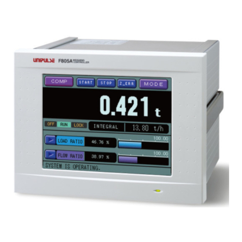
Unipulse F805AT-CK User manual

F805AT-CK CHECKER SCALE CONTROLLER
OPERATION MANUAL
01 Sep. 2022
Rev. 1.05

Introduction
I
Introduction
Thank you very much for purchasing our F805AT-CK Checker Scale Controller.
For good performance, and proper and safe use of the F805AT-CK, be sure to read this instruction
manual and properly understand the contents of it before use. Also, carefully keep this instruction
manual so that it can be referred to at any time.
When you use options please read a separate-volume (the manual for options).
Safety Precautions
In order to have an F805AT-CK used safely, notes we would like you to surely follow divide into
" " and " ", and are indicated by the following documents. Notes indicated
here are the serious contents related to safely. Please use F805AT-CK after understanding the contents
well.
For safety reasons, please read the following safety precautions thoroughly.
WARNING CAUTION
WARNING
This sign forewarns the presence of hazards that could result in serious injury or
fatality when incorrectly handled.
CAUTION
This sign forewarns the presence of hazards that could result in personnel injury or
property damage when incorrectly handled.

Safety Precautions
II
WARNING
●For the entire system to function safely when the F805AT-CK becomes faulty or
malfunctions, provide a safety circuit outside the F805AT-CK.
●Before using the F805AT-CK as described below, make sure to consult with our sales
personnel.
- Use in environments not described in the operation manual.
- Use greatly impacting human lives and assets, such as medical devices, transport devices
entertainment devices, and safety devices.
●Do not disassemble, repair, or modify the F805AT-CK. Doing so may cause a fire or an
electric shock.
●Do not install in the following environments.
- Places containing corrosive gas or flammable gas.
- Where the product may be splashed with water, oil or chemicals.
●Do not connect a commercial power source directly to the signal input/output terminals.
●Be sure to ground the protective ground terminal.
●The attached AC cable is designed for domestic use in Japan, and its rating is 125V AC, 7A.
For use at voltages exceeding the rating and for overseas use, have a separate AC cable
prepared.
●Before performing the following, make sure that no power is applied.
- Attachment/detachment of connectors of options, etc.
- Wiring/connection of cables to the signal input/output terminals.
- Connection to the ground terminal.
●For connection to the signal input/output terminals, check the signal names and pin
assignment numbers, and then carry out wiring properly.
●The connection to the RS-485 terminal block must use the crimp contacts.
Do not connect it the open-wire line.
●After wiring, be sure to mount the attached terminal block cover. Otherwise, it may cause an
electric shock. (at the DC spec.)
●To take measures against lightning surge, install a lightning surge protector (optionally
available).
●Do not connect anything to unused terminal(s).
●Before applying power, carefully check the wiring, etc.
This sign forewarns the presence of hazards
that could result in serious injury or fatality
when incorrectly handled.
Warning on design
Warning on installation
Warning on wiring

Safety Precautions
III
WARNING
●Use a power supply voltage and load within the specified and rated ranges.
●Do not damage the power cord. Doing so may cause fire or electric shocks.
●Do not touch any signal input/output terminal while applying power. Doing so may cause
electric shocks or malfunctions.
●If the cover of the main body is opened, it may cause an electric shock internally. Even if the
power is off, the internal capacitor is charged. Contact us for internal inspection or repair.
●In the case of smoke, an abnormal smell or strange sound, immediately turn off the power,
and disconnect the power cable.
●Lithium battery use in the F805AT-CK unit.
type: CR14250SE manufactured by Sanyo Electric, or equivalent
Voltage: 3 volts
Capacity: 850 mAh
This sign forewarns the presence of hazards
that could result in serious injury or fatality
when incorrectly handled.
Warning during startup and maintenance
CAUTION
●Use the F805AT-CK as it is incorporated in a control panel, etc.
●Do not install in the following environments:
- Locations where temperature or humidity exceeds specifications;
- Locations subjected to drastic temperature fluctuations or icing and condensing;
- Outdoors or locations above 2,000m;
- Locations exposed to direct sunlight;
- Locations subject to dust accumulation;
- Locations with poor ventilation;
- Locations with a lot of salt and metal powder;
- Locations where the main unit is subject to direct vibration and shock.
●Take adequate shielding measures when using at the following locations.
- Near a power line.
- Where a strong electric field or magnetic field is formed.
- Where static electricity, relay noise or the like is generated.
●Install the F805AT-CK as far away from devices generating high frequency, high voltage,
large current, surge, etc., as possible. Also, carry out wiring separately from their power
lines. Do not carry out parallel wiring and common wiring.
●Do not use it, broken down.
This sign forewarns the presence of hazards
that could result in personnel injury or property
damage when incorrectly handled.
Caution on installation

IV
About the power cable
CAUTION
●Tighten the screws for the signal input/output terminals at the specified torque.
If they are loose, shorts, fire or malfunctions may occur.
Tightening torque: 0.5N •m (at the DC spec.)
●For sensors, external inputs/outputs and options, use shielded cables.
●The temporary overvoltage applied to the power should not exceed 1500V.
●For turning on/off the power, be sure to keep intervals of 5 seconds or more.
●After power-on, make sure to warm up the F805AT-CK for at least 30 minutes or more before
use.
●If the F805AT-CK is not used by the specified method, its protective performance may be
impaired.
●Maintenance
- When performing maintenance, disconnect the power.
- Do not wipe with a wet rag, or with benzine, thinner, alcohol, etc. Doing so may cause
discoloration or deformation of the F805AT-CK. In the case of heavy contamination,
wipe off the contamination with a cloth after dipping it into a diluted neutral detergent
and wringing it well, and then wipe with a soft, dry cloth.
●When the F805AT-CK is shipped, spacers made of corrugated cardboard are used as
cushioning materials.
Though it is factory-designed so that shocks can sufficiently be absorbed, breakage may
result if shocks are applied when the spacers are reused for transportation. If you send the
F805AT-CK to us for repair, etc., take adequate measures against shocks by using
polyurethane materials, etc., separately.
●If you dispose of the product, handle it as industrial waste.
This sign forewarns the presence of hazards
that could result in personnel injury or property
damage when incorrectly handled.
Caution on wiring
Caution during startup and maintenance
Caution during transportation
Caution during disposal
CAUTION
●The power cable attached is an object for checking of operations.
Please use the power cable authorized in the country for employment.
This sign forewarns the presence of hazards
that could result in personnel injury or property
damage when incorrectly handled.

Product compliant to RoHS2 Directive
V
Product compliant to RoHS2 Directive
The parts and attachments (including the instruction manual, packaging box, etc.) used for this unit are
compliant with the RoHS2 Directive, restricting the use of hazardous substances with regard to adverse
effects on the environment and human body.
RoHS2 Directive
It is based on the restriction of the use of certain hazardous substances in electrical and electronic
equipment (EEE). The Directive restricts the use of specific substances in electrical and electronic
equipments that could harm environment and human body. The substances are lead, mercury, cadium,
hexavalent chromium, PBB (polybrominated biphenyls), PBDE (polybrominated diphenyl ethers),
DEHP (bis(2-ethylhexyl) phthalate), BBP (benzyl butyl phthalate), DBP (dibutyl phthalate), and DIBP
(diisobutyl phthalate).
Please inquire of our sales person about the RoHS2 Directive of the option.

CONTENTS
VI
CONTENTS
1.FEATURES OF F805AT-CK ......................................................................... 1
1-1.Dynamic Mode ..................................................................................... 1
1-2.Static Mode .......................................................................................... 3
1-3.Points to be Noted in Measuring .......................................................... 4
1-4.Interfaces of Weighing Controller ......................................................... 5
1-5.Graphic ................................................................................................ 5
2.APPEARANCE DESCRIPTION .................................................................... 6
2-1.Front Panel .......................................................................................... 6
2-1-1.Touch panel type color liquid display ......................................... 6
2-1-2.Power source lamp .................................................................. 10
2-2.Rear Panel ......................................................................................... 11
3.SCREEN COMPOSITION AND SETTINGS ............................................... 13
3-1.Screen Configuration Flow Chart ....................................................... 13
3-1-1.Entire screen ............................................................................ 13
3-1-2.Main screen (message) ........................................................... 14
3-2.The Way of Setting ............................................................................ 14
3-2-1.Setting item selection ............................................................... 14
3-2-2.Setting mode ............................................................................ 15
3-2-3.Setting mode of items on code ................................................ 16
4.WAY OF CONNECTION ............................................................................. 18
4-1.Load Cell Connection ......................................................................... 18
4-1-1.6-Wire connection ................................................................... 19
4-1-2.4-Wire connection ................................................................... 19
4-1-3.How to wire load cell connector ............................................... 20
4-1-4.Connecting load cells in parallel .............................................. 21
4-1-5.Sensor cable ............................................................................ 21
4-2.Connecting power input terminal at the DC Spec. ............................. 22
4-3.Connection of the protective ground .................................................. 22
4-4.SI/F 2-wire Serial Interface ................................................................ 23
4-5.SI/FII High Speed Bi-directional 2- Wire Serial Interface ................... 23
4-6.External In/Out Signal ........................................................................ 24
4-6-1.Control connector-pin assignment ........................................... 24

CONTENTS
VII
4-6-2.Equivalent circuit (input) ........................................................... 25
4-6-3.Equivalent circuit (output) ........................................................ 25
4-7.RS-232C Connector ........................................................................... 26
4-7-1.Connector pin assignment ....................................................... 26
4-7-2.Cable ........................................................................................ 26
5.CALIBRATION ............................................................................................ 27
5-1.What is Span Calibration ................................................................... 27
5-2.Calibration Procedure ........................................................................ 28
5-3.Secondary Calibration Procedure (Equivalent Calibration) ................ 29
5-4.Preparation for Calibration ................................................................. 30
5-4-1.LOCK release .......................................................................... 30
5-4-2.Load cell excitation .................................................................. 31
5-4-3.Unit ........................................................................................... 31
5-4-4.Decimal place .......................................................................... 31
5-4-5.Capacity ................................................................................... 31
5-4-6.Minimum scale division ............................................................ 32
5-4-7.Balance weight ......................................................................... 32
5-4-8.Gravitational acceleration ........................................................ 32
5-4-9.1/4 scale division ...................................................................... 33
5-5.Zero Calibration ................................................................................. 34
5-6.Span Calibration ................................................................................ 35
5-7.Do Secondary Calibration (Equivalent Calibration) ............................ 36
5-8.Net Over/ Gross Over ........................................................................ 36
6.FUNCTION SETTING ................................................................................. 37
6-1.Operation ........................................................................................... 37
6-1-1.Display frequency .................................................................... 37
6-1-2.Digital filter ............................................................................... 37
6-1-3.Analog filter .............................................................................. 37
6-1-4.Motion detection ....................................................................... 38
6-1-5.Zero tracking ............................................................................ 39
6-1-6.Digital zero ............................................................................... 40
6-1-7.Digital zero clear ...................................................................... 40
6-1-8.Digital zero regulation value ..................................................... 40
6-2.Function ............................................................................................. 41
6-2-1.Tare subtraction/ Tare subtraction reset .................................. 41
6-2-2.Preset tare weight 1/ Preset tare weight 2 ............................... 42
6-2-3.Auto accumulation command ................................................... 42
6-2-4.Weighing code selection/ Setting code selection ..................... 43
6-2-5.TARE/DZ key disablement ....................................................... 44
6-2-6.GROSS/NET key disablement ................................................. 44
6-2-7.Each code key disablement ..................................................... 45
6-2-8.Accumulation command acceptance ....................................... 45
6-2-9.Tare display ............................................................................. 45

CONTENTS
VIII
6-2-10.I/O monitor display ................................................................. 46
7.FUNCTION AS A WEIGHT CHECKER ...................................................... 47
7-1.About Measurement ........................................................................... 47
7-1-1.Dynamic mode ......................................................................... 47
7-1-2.Static mode .............................................................................. 48
7-1-3.Points to be noted in measuring .............................................. 49
7-2.Each Code ......................................................................................... 50
7-2-1.Final ......................................................................................... 50
7-2-2.Over ......................................................................................... 50
7-2-3.Under ....................................................................................... 51
7-2-4.Accumulation clear ................................................................... 51
7-2-5.Total comparison/ Total limit/ Count limit ................................. 51
7-3.Comparison ........................................................................................ 52
7-3-1.U/L limit comparison/ Upper limit/ Lower limit .......................... 52
7-3-2.Near zero comparison/ Near zero ............................................ 53
7-3-3.Over/Under comparison 1 ........................................................ 53
7-3-4.Complete output time ............................................................... 53
7-4.Sequence Mode ................................................................................. 54
7-4-1.Empty count/ Take in count ..................................................... 54
7-4-2.Average mode/ Sample mode ................................................. 54
7-4-3.Gross ratio ............................................................................... 56
7-4-4.One-touch final ......................................................................... 57
8.STATISTICS・ACCUMULATION CONTROL FUNCTION ......................... 58
8-1.Result ................................................................................................. 58
8-1-1.Result display screen ............................................................... 58
8-1-2.Statistical data display screen .................................................. 59
8-2.Accumulation Command Acceptance ................................................ 60
8-3.Accumulation Clear ............................................................................ 60
8-4.Total Comparison/ Total Limit/ Count Limit ........................................ 60
8-5.Auto Accumulation Command ........................................................... 62
9.GRAPHIC SCREEN .................................................................................... 64
9-1.Graphic Drawing Point ....................................................................... 64
9-2.Graphic Display .................................................................................. 64
9-2-1.Relative time/ Absolute time .................................................... 65
9-2-2.Graphic mode .......................................................................... 66
9-2-3.Trigger level ............................................................................. 67
9-2-4.X (Time axis)-end point ............................................................ 67
9-2-5.Y (Weight)-start point ............................................................... 67
9-2-6.Y (Weight)-end point ................................................................ 67

CONTENTS
IX
10.SYSTEM MODE ........................................................................................ 68
10-1.Back Light Auto. Light. ..................................................................... 68
10-2.Back Light Low Time ........................................................................ 68
10-3.Back Light ON Time ......................................................................... 68
10-4.Self-Check ....................................................................................... 69
10-5.Language ......................................................................................... 71
10-6.Pass Word ....................................................................................... 71
10-7.Lock (soft) ........................................................................................ 72
11.CONTROL I/O (EXTERNAL SIGNAL) ...................................................... 73
11-1.Control Connector-pin Assignment .................................................. 73
11-2.Equivalent Circuit (Input) .................................................................. 74
11-3.Equivalent Circuit (Output) ............................................................... 74
11-4.External Input Signal ........................................................................ 75
11-4-1.G/N <edge input> [pin 2] ........................................................ 75
11-4-2.Digital zero (D/Z ON) <edge input> [pin 3] ............................. 75
11-4-3.Tare subtraction (TARE ON) <edge input> [pin 4] ................. 75
11-4-4.Tare reset (TARE OFF) <edge input> [pin 5] ......................... 75
11-4-5.Accumulation command <edge input> [pin 8] ........................ 76
11-4-6.Accumulation clear <edge input> [pin 9] ................................ 76
11-4-7.Input signals used in weighing ............................................... 76
11-4-8.Code No. designation <level input> [pin 11 ~ 14, 36 ~ 39] .... 77
11-4-9.Code No. designation selection <level input> [pin 30] ........... 77
11-4-10.Graph drawing <edge input> [pin 32] ................................... 77
11-5.External Output Signal ..................................................................... 78
11-5-1.Near zero [pin 17] .................................................................. 78
11-5-2.Lower limit, Upper limit [pin 43, 44] ........................................ 78
11-5-3.Stable [pin 45] ........................................................................ 78
11-5-4.Weight error [pin 46] .............................................................. 78
11-5-5.Run or Total limit [pin 49] ....................................................... 78
11-5-6.Under, Go, Over [pin 21 ~ 23] ................................................ 78
11-5-7.Complete [pin 24] ................................................................... 78
12.INTERFACE .............................................................................................. 79
12-1.SI/F 2-Wire Serial Interface .............................................................. 79
12-2.SI/FII High Speed Bi-Directional 2- Wire Serial Interface ................ 80
12-3.RS-232C Interface ........................................................................... 82
12-3-1.Communication specifications ............................................... 82
12-3-2.Setting values for RS-232C ................................................... 82
12-3-3.Cable ...................................................................................... 83
12-3-4.Communication format ........................................................... 84
12-3-5.Communication Mode ............................................................ 92

CONTENTS
X
12-3-6.Transmission Format ............................................................. 94
13.OVER SCALE & ERROR .......................................................................... 96
13-1.Over Scale (Weight Error [Pin 46]) .................................................. 96
13-2.Calibration Error ............................................................................... 96
13-3.EXC Error ......................................................................................... 96
13-4.Priority of Error Display .................................................................... 96
14.TROUBLE SHOOTING ............................................................................. 97
15.BLOCK DIAGRAM .................................................................................. 102
16.DIMENSIONS ......................................................................................... 103
17.MOUNTING ON A PANEL ...................................................................... 104
18.SPECIFICATIONS .................................................................................. 105
18-1.Analog ............................................................................................ 105
18-2.Display ........................................................................................... 105
18-3.Configuration .................................................................................. 106
18-4.Control Input/Output Signal ............................................................ 106
18-5.Interface ......................................................................................... 106
18-6.General Specifications ................................................................... 108
18-7.Attachment ..................................................................................... 109
19.THE LIST OF INITIAL SETTING VALUE ................................................ 110
20.MODE SETTING TREE CHART ............................................................. 115
21.STATEMENT OF CONFORMATION TO EC DIRECTIVES
(Designated when it is shipped) .............................................................. 116

1.FEATURES OF F805AT-CK
1
1. FEATURES OF F805AT-CK
The F805AT-CK, which is a product that functions as a weight checker, can be used as a checker scale.
Measurement can be carried out in “DYNAMIC MODE” and “STATIC MODE”.
1-1. Dynamic Mode
Weighing starts when the weight exceeds the near zero, and the weighing stops when the weight drops
below the near zero or data is taken in by a fixed count.
Being independent of the weighing time, weighing can be performed with the weight value going
across the near zero. In other words, this mode is suitable for weighing when the belt speed and/or
measuring object size is nonconstant. (Refer to Fig. 1.)
Also, since no external signal is required, this mode has the advantage of being able to simplify your
system.
A A'
B
Take-in interval (Ta)
Take-in interval (Tb)
Near zero
0
0t
t
NET
NET
◇Short measuring object A
[Figure 1]
◇Long measuring object B
B'
Near zero

1.FEATURES OF F805AT-CK
2
Basically, set “EMPTY COUNT” at 0, and “TAKE IN COUNT” at the maximum value (999).
According to the measuring object weight, set an optimum value to “NEAR ZERO”.
For “SAMPLE MODE”, select the largest possible value at which the load becomes constant.
(Refer to Fig. 2.)
Take-in interval
Near zero
0t
NET
◇Good example
Take-in interval
0t
NET
With the SAMPLE MODE adjusted, the
position where the weight is flat is
acquired.
(The average of the data of this part is
taken. 50% applies in the figure.)
With the SAMPLE MODE set at 100%,
fluctuating data is acquired.
Since the near zero is inappropriate,
the near zero may be applied in a
position different from the proper one.
[Figure 2]
◇Bad example
Near zero

1.FEATURES OF F805AT-CK
3
1-2. Static Mode
Weighing starts when the weight exceeds a Near Zero set value after inputting an external start signal,
and the weighing stops when data is taken in by a fixed count. This mode is suitable for weighing when
the belt speed and/or measuring object size is constant. (Refer to Fig. 3.)
Basically, use the “SAMPLE MODE” at 100%. Adjust the “EMPTY COUNT” so as not to acquire
data as long as the load is unstable. Also, adjust the “TAKE IN COUNT” so as to acquire data where
the load is applied uniformly. (Refer to Fig. 4.)
C
◇Heavy measuring object C
[Figure 3]
◇Lightweight measuring object D
D D'
C' NET
t
C
D
0
Measurement Start
Near Zero
Near Zero OFF ON
Empty
Take-in
interval
count
interval
Since the empty count interval is short, fluctuating
data is included in the take-in interval.
Take-in interval
0t
NET
◇Good example
◇Bad example
The EMPTY COUNT is set so as not to acquire
fluctuating data.
Empty count
Data of the part where the load is
uniform is acquired.
Take-in interval
0t
NET
Empty count
Since the take-in interval is long,
data of the part where the load is
nonuniform is acquired.
[Figure 4]
interval
interval

1.FEATURES OF F805AT-CK
4
1-3. Points to be Noted in Measuring
Filter settings
Adjust the “DIGITAL FILTER” and “ANALOG FILTER” in the “OPERATION” settings, and set
optimum values so as to remove noise components, such as vibration, and to obtain sufficient rising
characteristics.
The relationship between parameter changes, stability, and response is as shown in the table below.
(Refer to "6-1-2. Digital filter" on Page37, "6-1-3. Analog filter" on Page37.)
Prevention of double placement
Double placement is a state in which two or more measuring objects are placed on the load-sensing part.
Take the distance (d) between measuring objects longer than the load-sensing part (l). Be aware that
accurate weighing cannot be performed especially in “DYNAMIC MODE”. (Refer to Fig. 5.)
Long measuring objects
Compared with shorter measuring objects, longer ones cause the entire load to be applied to the load
cell for a shorter time.
Adjust the belt speed, etc., so that a sufficient data count can be obtained. (Refer to Fig. 6.)
Setting of ANALOG FILTER Low frequency High frequency
Stability Stable ⇔Unstable
Response Slow ⇔Fast
Setting of DIGITAL FILTER High count Low count
Stability Stable ⇔Unstable
Response Slow ⇔Fast
F
Near zero
0t
NET
[Figure 5]
d
l
E F
◇ Example of double placement (d < l)
There is a possibility that
E
the near zero may not be applied.
0t
NET
[Figure 6]
G G'
H H'
TG
TH
(TG>TH)

1.FEATURES OF F805AT-CK
5
1-4. Interfaces of Weighing Controller
F805AT-CK can communicate with variety of peripheral equipment through standard or optional
interface module. Sketch below shows example of such interfacing.
1-5. Graphic
F805AT-CK possesses graphic display which enables to display input wave form.
F805AT-CK enables to weigh the weight change in detail with passing of time by moving a cursor.
F805AT-CK
Printer
Display
Data
converter
Supported
device
D/A converter (Option)
Valve etc.
RS-232C
RS-485 (Option)
SI/F
SI/FⅡ
CC-Link (Option)
DeviceNet (Option)
Mitsubishi PLC
Omron
CompoBus/D etc.
F805AT-CK
Supported
device

2.APPEARANCE DESCRIPTION
6
2. APPEARANCE DESCRIPTION
2-1. Front Panel
2-1-1. Touch panel type color liquid display
A touch panel type color liquid display enables to display indicated values and graphs and set various
items.
【Comparison screen】
Power source
Touch panel type
color liquid display
Shift to Message screen.
Digital Zero is carried out.
(TARE for displays other than GROSS.)
Main display change
Shift to Setting
Status display
Set values display
Main display
mode selection display.

2.APPEARANCE DESCRIPTION
7
Main display
Weight value Displays GROSS, NET, ERROR, or RESULT.
When Error occurred, the display shows Error and Weight value alternately.
1/4 scale division Displays the condition of 1/4 scale division.
It is displayed only when the weight display is GROSS or NET.
Unit Displays the unit already set in unit setting.
Status display
EMP Lights during empty counting in weighing.
SMP Lights during counting in weighing.
LOCK Indicates the conditions of the lock switch and soft lock as:
Highlights in red when the lock switch is ON, and
Highlights in orange when the soft lock is ON.
Priority is given to the lock switch.
NZ Lights when the weight is the NEAR ZERO set value or less.
ZALM Lights when a zero alarm is given.
OK Displays the judgment state of RESULT as follows:
Over: HI (blue), Go: OK (light orange), Under: LO (red).
COMPL During Complete signal is ON, COMPL highlights in sky blue.
STAB STAB highlights in green during weight value is stable.
RUN When the TOTAL LIMIT is ON, TOTAL highlights in red.
Also, during access to NOV RAM after changing set values, etc., NOV is
displayed.
During normal operation in cases other than those above, the display highlights in
sky blue.
Set values display
FINAL Set the FINAL value.
Change the FINAL value by pressing the button.
Depending on the setting, the following modes are available: mode in which the
screen is switched to the numerical input screen; mode in which the current value
is taken in as the FINAL value; and mode in which the latest RESULT is taken in
as the FINAL value.
CODE Displays the currently weighing code number.
The screen is switched to the CODE setting screen by pressing the button.
OVER Displays the calculation result of FINAL SETTING + OVER SETTING.
The screen is switched to the OVER setting screen by pressing the button.

2.APPEARANCE DESCRIPTION
8
UNDER Displays the calculation result of FINAL SETTING - UNDER SETTING.
The screen is switched to the UNDER setting screen by pressing the button.
RESULT Displays the result of weighing.
The display is switched between the result of weighing and the error in weighing
by pressing the button.
COUNT DISPLAY Display the OK count and the error count.
The error count display becomes LO display on the【Comparison screen】on
Page6.
Each time the LO part is pressed, switching is done between HI, LO and NG.
HI: displays the HI count.
LO: displays the LO count.
NG: displays the sum of the HI count and LO count.
Main display change
Each time the button is pressed, the weight value on the main display is switched.
【Message screen】
Main display, Status display
Same as the COMPARISON screen.
Message display
The contents of display are switched by pressing the key at the lower right.
Error status Displays the details in the case of a calibration error and over scale.
GROSS → NET → ERROR → RESULT
Shift to Graph screen.
Digital Zero is carried out.
(TARE for displays other than GROSS.)
Main display change
Message display
Shift to Setting
Status display
Main display
mode selection display.
Error status → Weighing status display → Set values display → Blank display

2.APPEARANCE DESCRIPTION
9
Weighing status display Displays the current weighing status.
(DYNAMIC MODE/ STATIC MODE)
Set values display Displays the following data.
CODE Displays the weighing CODE number.
CNT. Displays the COUNT of weighing.
FINAL.C Displays the FINAL COUNT of judgment.
OVER.C Displays the OVER COUNT of judgment.
UNDER.C Displays the UNDER COUNT of judgment.
FINAL.S Displays the FINAL SETTING set value.
OVER.S Displays the OVER SETTING set value.
UNDER.S Displays the UNDER SETTING set value.
OVER Displays the calculation result of FINAL SETTING + OVER SETTING.
UNDER Displays the calculation result of FINAL SETTING - UNDER SETTING.
Blank display Displays nothing in the message display area.
【Graph screen】
Return to Comparison screen. Main display change
Shift to Setting
Starting Graph drawing.
Shift Cursor Right/Left.
Displays the current
mode selection display.
Select ON/OFF.
weighing status.
①
◇Explanation of graphic colors
② ③ ④ ⑤
①: Displayed in pink when the weight is the
NEAR ZERO set value or less.
(The NZ lamp lights.)
②: Displayed in sky blue during empty counting.
(The EMP lamp lights.)
③: Displayed in yellow during counting.
(The SMP lamp lights.)
④: Displayed in green in cases other than ①to ③.
(Any of HI, OK and LO lights while judgment
is output.)
⑤: Displayed in pink when the weight is the
NEAR ZERO set value or less.
At the beginning of each of ②, ③, and ⑤(at each
ON edge), the display is enlarged in each color.
Table of contents
Other Unipulse Controllers manuals
Popular Controllers manuals by other brands

gefran
gefran GTF-Xtra Installation and operation manual

Rockwell Automation
Rockwell Automation Allen-Bradley SMC-3 Installations

Seko
Seko Pool Basic Pro Evo user manual

Stellar Lighting
Stellar Lighting LEK-431 APP user manual

Toss
Toss ROPEX RESISTRON RES-407 operating instructions

Embedded Artists
Embedded Artists LPCXpresso user guide