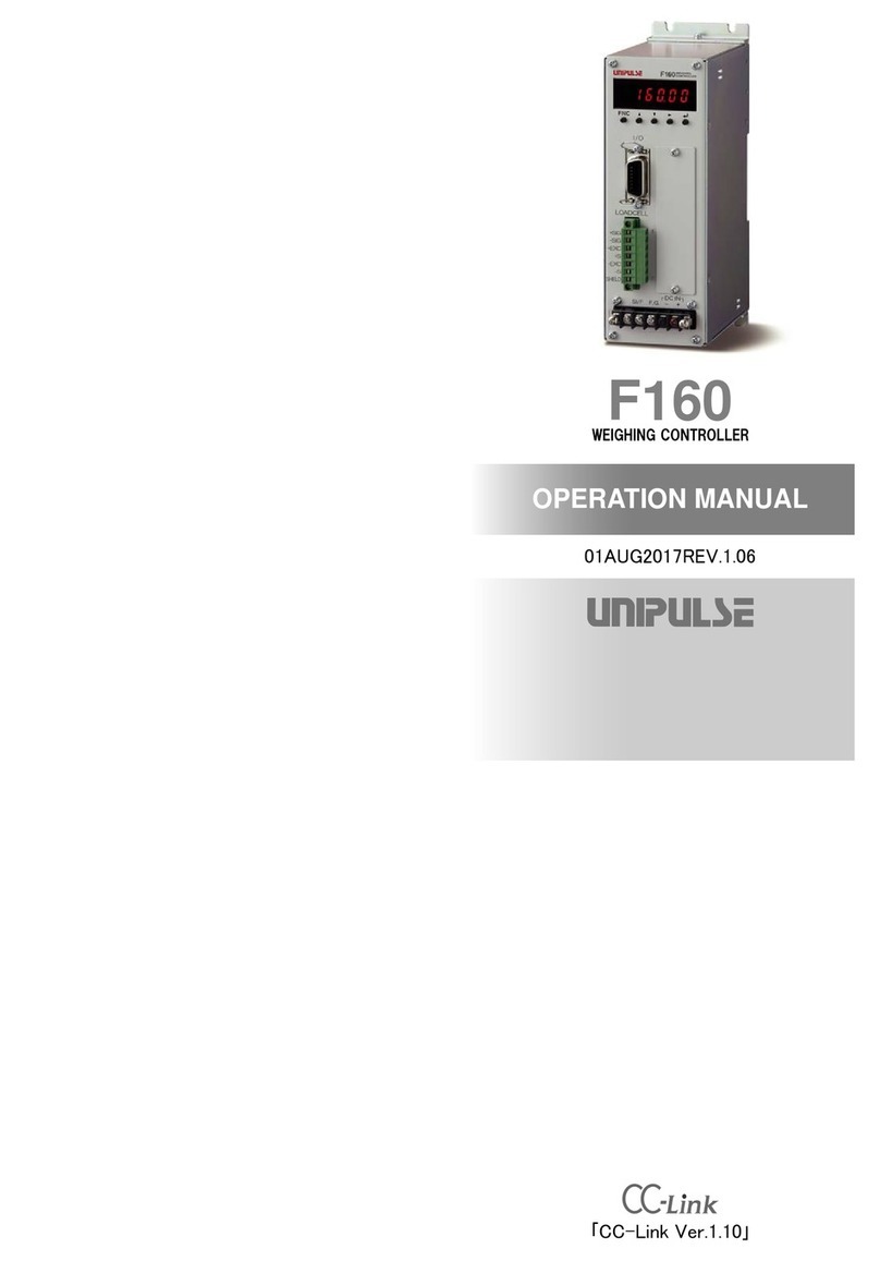
Unipulse F156 User manual

F156
WEIGHING CONTROLLER
07 JUN. 2012
REV. 1.40
OPERATION MANUAL
「CC-Link Ver.1.10」

INTRODUCTION
INTRODUCTION
Thank you for purchasing our F156 weighing controller.
This machine based on our long-established weighing technology, is standard-loaded with
Mitsubishi Electric’s field network CC-Link interface, facilitates linking with a PLC
(Programmable Logic Controller). Also, as a fail-safe measure, it is equipped with the function
of automatically shutting off the load cell power supply when the load cell and lines are short-
circuited or overloaded.
Please carefully read this operation manual before using the F156 in order to fully deliver
excellent performance and proper and safe use.
Description in this manual
Basically, initial (default) values are underlined for selecting settings and for setting values.
Example) Digital filter
About the operational changes of the external input/output functions
In F156s with software versions earlier than 2.22, fixed functions would be assigned to external
control inputs, but these have been made selective in the same way as external control outputs;
external control input selection 0 to external control input selection 4 are added to setting codes
from 70 to 74.
For the details of respective functions, see "8.EXTERNAL INPUT/OUTPUT (Amphenol
Connector)" on p.117.
In the initial condition, the settings are as in the case of use of the simple comparison mode;
therefore, if you use the sequence mode and request the conventional assignments, please make
settings as follows:
6: 64 times
4: 16 times
8: 256 times 5: 32 times
Setting
* In this case, “4: 16 times” is the initial value.
7: 128 times
2: 4 times
0: OFF3: 8 times
1: 2 times
For use of the sequence mode (Setting code 46 “Sequence Mode” is 1)
Setting code Setting value Pin No. FUNCTION
70 8 10 No function
71 5 11 Feed/Discharge
72 2 12 Tare subtraction
73 6 13 Sequence start
74 7 14 Sequence stop

Safety Precautions
Safety Precautions
Be sure to read for safety.
In order to have an F156 Weighing Controller used safely, notes I would like you to surely
follow divide into and , and are indicated by the following
documents. Notes indicated here are the serious contents related safely. Please use after
understanding the contents well.
WARNING CAUTION
WARNING
Misuse may cause the risk of death or serious
injury to persons.
CAUTION
Misuse may cause the risk of injury to persons
or damage to property.

Safety Precautions
WARNING
●Use F156 with correct supply voltage.
●Carefully check wiring, etc. before applying power.
●Do not disassemble the main body for modifications or repair.
●Be sure to use crimp contacts for connection to terminal blocks, and do not to connect
bare wires as they are.
●Be sure to ground the protective ground terminal.
●When smoke, a nasty smell, or strange sound, please shut off a power supply
immediately and extract a power supply cable.
●Do not install in the following environments.
- Placescontaining corrosive gas or flammable gas.
- Where the product may be splashed with water, oil or chemicals.
●About the built-in lithium battery
Never disassemble, deform under pressure or throw the battery
into fire.The battery may explode, catch fire or leak.
- Battery
Model : CR14250SE made by SANYO Electric Co., Ltd.
Nominal voltage : 3V
Nominal electric capacity : 850mAh

Safety Precautions
CAUTION
●Be sure to disconnect the power cable when performing the following.
- Attachment/detachment of load cell connector, external I/O connector, console or
RS-232C connection connector.
- Wiring/connection of cables to terminal blocks.
- Connection of the ground line.
●For connection to the signal I/O terminal block, wire correctly after checking the signal
names and terminal block numbers.
Also, turn off the power of the main body before connection/wiring to the signal I/O
terminal block.
●Use shielded cable for connection with load cell unit and RS-232C.
●Take adequate shielding measures when using at the following locations.
- Near a power line.
- Where a strong electric field or magnetic field is formed.
- Where static electricity, relay noise or the like is generated.
●Do not install in the following environments.
- Places exposed to direct sunlight.
- Where the temperature and/or humidity exceeds the range in the specifications.
- Placeswith large quantities of dust, salt or iron powder.
- Where the main body is directly affected by vibration or shock.
●Do not use it, broken down.
●When you send F156 by repair etc., please take sufficient measures against a shock.

CONTENTS
CONTENTS
1.PART NAMES AND FUNCTIONS ..........................................1
2.CONNECTION ........................................................................5
2-1.Load cell Connection ................................................................................ 5
2-1-1.Load cell signals ........................................................................................... 5
2-1-2.Connecting load cells in parallel ................................................................. 6
2-2.CC-Link Interface Connection ................................................................... 8
2-3.Console Connection .................................................................................. 9
2-4.External Input/Output (Amphenol Connector) Connection ................. 10
2-5.SI/F Interface Connection ....................................................................... 11
2-5-1.Connection to a cage clamp type terminal block .................................... 11
2-5-2.Connection of external devices ................................................................ 12
2-6.RS-232C Interface Connection ............................................................... 13
3.CC-LINK INTERFACE ..........................................................14
3-1.Outline ...................................................................................................... 14
3-2.Communication Setting Rotary Switch ................................................. 14
3-3.Communication Status Indicators ......................................................... 14
3-4.Outline of the Buffer Memory for Communication ............................... 15
3-5.Buffer Memory Assignments .................................................................. 16
3-6.Setting Procedures .................................................................................. 28
3-7.Sample Ladder ......................................................................................... 31
4.CALIBRATION ......................................................................36
4-1.What is Calibration? ................................................................................ 36
4-2.Operation of Actual Load Calibration .................................................... 37

CONTENTS
4-3.Actual Load Calibration .......................................................................... 38
4-3-1.Calibration lock release ............................................................................. 38
4-3-2.Host connection ......................................................................................... 39
4-3-3.Decimal place .............................................................................................. 40
4-3-4.Capacity ....................................................................................................... 41
4-3-5.Minimum scale division ............................................................................. 42
4-3-6.Balance weight ........................................................................................... 43
4-3-7.Zero calibration ........................................................................................... 44
4-3-8.Span calibration .......................................................................................... 47
4-3-9.Calibration lock ........................................................................................... 49
5.WEIGHT DISPLAY ................................................................50
5-1.Gross and Net Weight • Tare Weight ..................................................... 50
5-2.Weight Value Reading ............................................................................. 51
6.FUNCTIONS ..........................................................................52
6-1.Tare Subtraction ...................................................................................... 52
6-2.Preset Tare Weight .................................................................................. 53
6-3.Digital Zero Regulation Value ................................................................. 55
6-4.Digital Zero ............................................................................................... 56
6-5.Motion Detection ..................................................................................... 57
6-6.Zero Tracking ........................................................................................... 59
6-7.Gravitational Acceleration ...................................................................... 61
6-8.Digital Filter .............................................................................................. 62
6-9.Analog Filter ............................................................................................. 63
6-10.Net Over .................................................................................................. 64
6-11.Gross Over ............................................................................................. 65
6-12.Discharging Control Mode .................................................................... 66
6-12-1.Feeding Weighing and Discharging Weighing ...................................... 66
6-12-2.Control mode ............................................................................................ 72
6-12-3.Simple Comparison Control and Sequence Control ............................. 73
6-12-4.Final / Set point2 / Set point1 / Compensation / Over / Under .............. 75
6-12-5.Upper limit / Lower limit / Near zero ....................................................... 78
6-12-6.Over/under comparison / Upper/lower limit comparison 1 /
Near zero comparison ............................................................................. 79
6-12-7.Over/under comparison mode ................................................................ 81

CONTENTS
6-12-8.Upper/lower limit comparison 2 .............................................................. 82
6-12-9.Comparison inhibit time / Judging time / Complete output time ......... 83
6-12-10.Complete output mode .......................................................................... 85
6-12-11.Auto free fall compensation /
Auto free fall compensation regulation /
Average count of auto free fall compensation /
Auto free fall compensation coefficient ............................................... 86
6-13.Sequence Control .................................................................................. 91
6-13-1.Normal sequence (with judgment) .......................................................... 91
6-13-2.Sequence with adjust feeding valid ........................................................ 95
6-13-3.Sequence without judgment .................................................................... 98
6-13-4.About the stop signal ............................................................................... 99
6-13-5.Relationship between auto zero times, judging times,
and auto free fall compensation ........................................................... 100
6-13-6.Sequence Error ....................................................................................... 102
7.REMOTE CONSOLE UNIT .................................................103
7-1.C110 Operation ...................................................................................... 104
7-2.C120 Operation ...................................................................................... 109
7-3.Mode Tree Chart .................................................................................... 114
8.EXTERNAL INPUT/OUTPUT (Amphenol Connector) ......117
8-1.Connector Pin Assignments ................................................................ 117
8-2.Output (Meanings of Signals) ............................................................... 118
8-3.Input (Meanings of Signals) .................................................................. 119
9.SI/F 2-WIRE SERIAL INTERFACE .....................................121
10.RS-232C INTERFACE ......................................................123
10-1.Communication Settings .................................................................... 123
10-2.Connector Pin Assignments .............................................................. 124
10-3.Communication Format ...................................................................... 125
10-4.List of Set Value ................................................................................... 129
10-5.List of Command ................................................................................. 133

CONTENTS
11.THE LIST OF INITIAL SETTING CODE ...........................134
11-1.Setting Range Details of the Set Value .............................................. 139
12.ERROR CODES ................................................................144
13.DIMENSIONS ....................................................................146
14.BLOCK DIAGRAM ............................................................147
15.SPECIFICATIONS ............................................................148
15-1.Analog section ..................................................................................... 148
15-2.Setting section ..................................................................................... 148
15-3.Interface ................................................................................................ 149
15-4.General performance .......................................................................... 149
15-5.Accessories ......................................................................................... 150

1.PART NAMES AND FUNCTIONS
1
1.PART NAMES AND FUNCTIONS
◇Front Panel
②CC-Link I/F
connector
①Load cell connector
③CC-Link I/F
station number setting
rotary DIP SW
④CC-Link I/F
baud rate setting
rotary DIP SW
⑤CC-Link I/F
status indicators (red)
⑬Power and system indicator
(green)
⑫Frame ground terminal ⑪AC power input terminals
⑥Setting remote console
unit / RS-232C connector
(exclusive)
⑦External input/output
connector
(Amphenol 14P)
⑧SI/F interface clamp
connector
⑨RS-232C communication
format and memory
setting DIP SW
⑩RS-232C mode and baud
rate setting rotary DIP SW

1.PART NAMES AND FUNCTIONS
2
①Load cell connector
Connect a load cell by using the included connector (female).
②CC-Link I/F connector
Connect a CC-Link interface cable by using the included connector (female).
③CC-Link I/F station number setting rotary DIP SW
Set a CC-Link I/F station number with two switches: first and second digits. The setting range is
1 – 63.
④CC-Link I/F baud rate setting rotary DIP SW
The setting range is 0 – 4.
⑤CC-Link I/F status indicators (red LED)
Monitor the CC-Link I/F communications status.
⑥Setting remote console unit/RS-232C connector
(Usable exclusively)
For the RS-232C, use the attached connector.
Setting Baud rate (bps)
0156k
1625k
22.5M
3 5M
4 10M
LED name LED ON LED OFF LED Blinking
RUN ・Normal ・Reset action
・No communication
SD ・Transmitting
RD ・Receiving
ERR ・Setting error
・CRC error
・Fault
・Normal ・Power-on-time
switch setting
changed

1.PART NAMES AND FUNCTIONS
3
⑦External input/output connector (amphenol 14P)
Feed/Discharge control outputs, control inputs, etc., are assigned as itemized below.
Open collector output: 7 ports
Contact input (photocoupler primary): 5 ports
Common (insulated power supply ground): 2
⑧SI/F interface (clamp connector)
This is a 2-wire serial interface to connect UNIPULSE-manufactured printer, external display,
etc., which is a nonpolar type, and to which up to three external devices can be connected in
parallel. For connection, parallel two-core cables, cabtyre cables, and the like can be used.
⑨RS-232C communication format and memory setting DIP SW
Switch No. 1 - 4 are switches to set the RS-232C communication format, No. 5 is a switch to
initialize set values from setting code 00 to 09,13and 19, No. 6 is a lock switch to prevent
rewriting of calibration data, etc. For details of the RS-232C, see "10.RS-232C INTERFACE"
on p.123.
List of functions
Note 1) Set values other than those stored in NOV.RAM are initialized.
(For details, see "11.THE LIST OF INITIAL SETTING CODE" on p.134.)
No. Function ON OFF Validation
timing
6 Memory lock Valid Invalid Always
5Memory clear Note 1) Clear Not clear
Only at
start-up
4 Parity bit Odd Even
3 Parity bit Available Unavailable
2 Stop bit 2bit 1bit
1 Data length 7bit 8bit

1.PART NAMES AND FUNCTIONS
4
⑩RS-232C mode and baud rate setting rotary DIP SW
Set the console mode at 0, and the baud rate in the RS-232C communication mode at 1 – 6 as
follows:
⑪AC power input terminals (red screws)
Input 100V 50/60Hz as the standard.
⑫Frame ground terminal
Be sure to ground (low ground resistance where possible).
⑬Power and system indicator (green LED)
LED ON during normal operation, functioning as a power lamp.
LED blinking during calibration, and when a fatal system error occurs.
List of functions
* Obstacles may be failure, mis-wiring, overload, etc., of the load cell.
No. Mode and baud rate
0 : Console mode (C110 or C120)
1 : 1200 bps
2 : 2400 bps
3 : 4800 bps
4 : 9600 bps
5 : 19200 bps
6 : 38400 bps
7 to 9 : Setting disabled
Rotary switch (mode and baud rate)
RS-232C communication mode
LED status System status Remark
LED ON During normal operation
LED Blinking with
50% duty
During calibration Automatically restored
to the lighting state when
calibration is normally
completed
LED Blinking with
low duty at a short
lighting time
Load cell power supply
shutdown with voltage
trouble between power
feedback +S and –S
Remove obstacles, and
then turn the power off
and on again. *
LED Blinking with
high duty at a long
lighting time
Voltage drop of the back-
up lithium battery
For replacement of the
battery, contact us.

2.CONNECTION
5
2. CONNECTION
2-1. Load cell Connection
This connector is for connecting a load cell. The adaptable plug is a HIROSE-manufactured JR-
16PK-7S (attached) or its equivalent.
2-1-1. Load cell signals
Pin No. Signal (6-wire) Signal (4-wire)
1+EXC +EXC
2+S(connect 1 to 2)
3-S-EXC
4-EXC (connect 3 to 4)
5+SIG +SIG
6-SIG -SIG
7 SHIELD SHIELD
12
345
6
7
-S
+EXC
-SIG
+S
+SIG
SHIELD
-EXC
+EXC
+S
-S
-EXC
+SIG
-SIG
SHIELD
+IN
-OUT
-IN
+OUT
(4-wire does not have +S and -S.)

2.CONNECTION
6
2-1-2. Connecting load cells in parallel
Some industrial applications require several load cells connected in parallel (e.g., tank or flow
scales).
A summing junction box should be used to facilitate connection and corner correction.
R
R
R
R
R
R
+EXC
-SIG
+SIG
-EXC
+EXC
-SIG
-EXC
+SIG
F. G
+S
-S
‘n’ (number) load cells connected in
parallel are considered one unit whose
capacity is ‘n’ x rated capacity of load
cells (load cells must have the same
capacity, bridge resistance, and mV/V).
The averaging resistor (R) must be in
same relative ratios with a low
temperature coefficient.
Averaging resistors are not needed if
load cells were designed for parallel
connection.
CAUTION
When connecting several load cells in parallel, load cell capacity should be higher than
expected load to compensate for mechanical shock or eccentric loading.
R
R

2.CONNECTION
7
CAUTION
・The load cell excitation voltage of the F156 is 10V. Unless its maximum
excitation voltage is 10V or more, the load cell may generate heat or be
damaged.
・For connecting a 4-wire load cell to the F156, be sure to connect +EXC and
+S, and –EXC and –S. Even if +S and –S are not connected, normal
operation will seem to be performed, but the load cell may generate heat or
be damaged because excessive voltage is applied.
+IN
-OUT
-IN
+OUT
Load cell
1
2
3
4
5
6
7
+EXC
+S
-S
-EXC
+SIG
-SIG
FG
Be sure to
connect here.

2.CONNECTION
8
2-2. CC-Link Interface Connection
Adaptable plug : WAGO 721-105/037-000 (Attachment)
Name Signal type Remarks
DA DA side signal line 110Ωtermination resistance
between them at a bus end
DB DB side signal line
DG Signal line ground
SLD Shield Cable shield
FG Frame ground
Termination
resistance (110Ω)
Adaptable cable:
KURAMO-
manufactured
FANC-SB11 or
its equivalent
・Unsheathe the individual cable
approximately 10mm, insert it in the
upper round hole, and clamp it.
・At this time, operate the lever with your
thumb, while pinching the plug by
hand as shown in the illustration on
the left-hand side.
・Never operate the lever as the plug is
connected; otherwise, the board may
be damaged.
How to connect
CAUTION
When the DA and DB signal lines and resistance are to be connected to
the connector, be aware that poor contact may result if the nipping
conditions differ between the leg of the resistance and signal lines.

2.CONNECTION
9
2-3. Console Connection
The setting remote console unit (C110/C120) can display all commands, parameter settings,
weight values, and status.
SET
ENT
123
46
5
789
0*#
CONSOLE
SET CLR ENT
C120
CONSOLE
C110

2.CONNECTION
10
2-4. External Input/Output (Amphenol Connector) Connection
The adaptable connector (plug) is DDK-manufactured 57-30140 (included) or its equivalent.
Connect referring to the internal circuit diagram shown below.
For input
The signal input/output circuit inputs signals by short-circuiting and opening the input and
COM terminals.
Short circuits are made by contact (relay, switch, etc.) or noncontact (transistor, TTL open
collector output, etc.)
For output
The signal output circuit outputs signals by means of a transistor open collector.
COM
push
switch
toggle
switch relay
+5V
TTL open-collecter
F156
IN
IN
Open OFF
Short ON
Ic = 6mA
inside
transistor
approx.
・Use external elements which withstand Ic=10mA.
・Leakage of external elements must be within 100μA.
Vcc
(ON when IN is HI )
COM
spark killer
load
spark killer
DC Power
varistor
load
AC Power
relay
Vext
Output data Tr
0 OFF
1 ON
F156
inside
Vceo=30v (max)
Ic=50mA (max)
・Use external power source for driving relay (vext) .
・Do not short-circuit the load,such as a coil of relay ,that will break the
output transistor.
・Connect a surge absorber or a spark killer to the relay circuit as shown
in the draft so that to reduce noise trouble and extend the life of relay.
VCC +5V

2.CONNECTION
11
2-5. SI/F Interface Connection
2-5-1. Connection to a cage clamp type terminal block
Connect to the cage clamp type terminal block by using the included mini-screwdriver.
1. Unsheathe the electric wire to be connected 5 – 6mm, and twist its end to such an extent that
it will not become loose.
2. Firmly insert the screwdriver into the upper hole while slightly pushing it up.
3. Insert the electric wire into the right hole so as not to loosen its end.
4. Pull out the screwdriver.
5. Lightly pull the electric wire to make sure that it is securely clamped.
CAUTION
・The electric wire connectable to the cage clamp type terminal block is 0.2
to 2.5mm2.
・Do not attach a crimp contact to the end of the electric wire, or solder it.
・To connect two or more electric wires, twist them together beforehand.
Table of contents
Other Unipulse Controllers manuals
Popular Controllers manuals by other brands

MegaPoints Controllers
MegaPoints Controllers Servo Controller user guide

Tescom
Tescom RMP-X1 Installation and user guide

Harman
Harman FG2106-04 quick start guide

Toshiba
Toshiba TS3000 Series instruction manual

Carel
Carel easy quick start guide

Precision Digital Corporation
Precision Digital Corporation Helios PD2-6210 instruction manual