Uniq USS-300 User manual

USS-300/USS-301
CCDCamera User's Manual
091-0300 V1.2
08-09-17

0
Tableof Contents
Warning ....................................................................................................................................................1
Precautions ..............................................................................................................................................1
Limited Warranty..................................................................................................................................... 1
1. Introduction .........................................................................................................................................2
1.1 GeneralDescription ...............................................................................................................2
1.2 Features .................................................................................................................................2
1.3 Applications ............................................................................................................................ 2
1.4 CCD ImagerSpectralResponse Curve .................................................................................2
1.5 Camera Specifications ...........................................................................................................3
1.6 Camera Dimension ................................................................................................................ 3
2. Camera Setup ......................................................................................................................................4
2.1 Basic Camera Setup .............................................................................................................. 4
2.2 Camera and Frame GrabberSystem Setups .......................................................................... 4
3. Camera Functions ...............................................................................................................................5
3.1 12-Pin Connector................................................................................................................... 5
3.2 Mode Switch Selection ..............................................................................................................5
3.3 ShutterSpeed DialSwitch .....................................................................................................5
3.4 Normaland Asynchronous Capture Mode (NRM/ASM).........................................................6
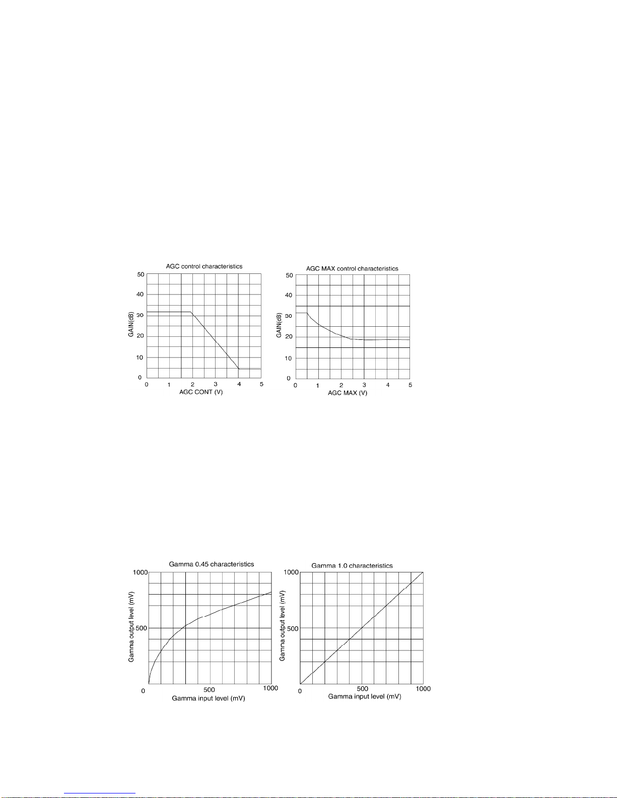
3.5 Gain ControlMode .................................................................................................................6
3.6 Gamma 1.0 and 0.45 Mode ................................................................................................... 6
3.7 Field and Frame Mode (FLD/FRM)........................................................................................ 7
4. Timing Signals .....................................................................................................................................8
4.1 Integration ............................................................................................................................... 8
4.2 Strobe ..................................................................................................................................... 8
5. Camera Malfunction ............................................................................................................................9
6. Technical SupportInformation ..........................................................................................................9

1
WARNING
TO PREVENT FIRE OR ELECTRIC SHOCKHAZARD,
DO NOT EXPOSE THIS CAMERA UNIT TO RAIN OR MOISTURE.
DO NOT ATTEMPT TO REMOVE CAMERA COVER OR MODIFY THE CAMERA UNIT,
WARRANTY WILL BE VOIDED.
PRECAUTIONS
Do dotattemptto disassemble, modify, or repair the camera. ContactUNIQ forhelp.
Do notpointthe camera atbrightobjects,such as the sun, fora long period. Itmay cause CCD blooming
and permanentdamages.
Do notoperate the camera beyond the temperature range. Avoid using the cameraabove 90%humidity.
Do notuse unregulated power supplysource.
Do nottouch CCD glass cover withfingers or anyhard objects other than professional glass cleaning
solvents.
Limited Warranty
UNIQ warrants to theoriginalcustomer to be free from defects in material and workmanship for twofull
years from the date oforiginal purchase. This warrantycoversfailures ordamages due to defects in
material or workmanship, which occur during normal use. It does notcover damages or failures, which
resultfrom shipment, mishandling, abuse, misuse, or modification.
A Return MaterialAuthorization (RMA)number is required prior toreturning anyUNIQ productfor repair
or replacement.
This proprietarydocumentmaynotbe reproduced or photocopied withoutthe consentofUNIQ. UNIQ
makes no warrantyor assumesno responsibilityfor anyerrors,which may appear in this document.
UNIQ reserves the rightto make changeswithoutnotice or obligation.

2
1. Introduction
1.1General Description
The USS-300/USS-301 series is an automatic exposure control(electronic shutter)camera using nearinfrared
(NIR)CCD imager. The camera is fourtimes more sensitive than the conventionalCCD camera at 945 nm
wavelength. Smearissignificantly reduced and dynamic range is much greaterthan the conventionalCCD
cameras. The camera works very well between low light and sunlight conditions. The high gain circuitry provides
clearvideo quality at low light condition. In adaylight condition, thecamera will automatically covert the saturated
incoming light source into a constant viewable video levelwith its auto electronic shuttercontrol.
1.2Features
•0.0005 lux(AGC max.)min. illumination
•High sensitivity (high gain)
•1/2”EXview HAD CCD*Imager
•768 x494 (EIA);752 x582 (CCIR)
•Auto electronic shuttercontrol
(1/60 – 1/100000 sec.)
•56 dB (AGC Off)
•Compact Size and lightweight
•AGC/MGC selectable
•Gamma1.0/0.45 selectable
1.3Applications
USS-300/USS-301 applications include low light, airborne, outdoorsurveillance, vehicles and unmanned vehicles,
and otherapplications where highgain and an auto iris function are needed without using an auto iris lens.
1.4CCD Imager SpectralResponseCurve
*
EXview HAD CCD is a registered trademark of Sony Corporation.

3
1.5CameraSpecifications
Model
USS-300 (EIA) USS-301 (CCIR)
CCD Sensor ½” Interline-Transfer EXview HAD CCD
Chip Size 6.4 mm x4.8 mm
Effective Pixels (H x V) 768 x494 752 x582
Unit Cell Size (H x V) 8.4
µ
mx9.8
µ
m 8.6
µ
mx8.3
µ
m
Scanning 525 TV lines, 2:1 Interlaced or Non-
interlaced 625 TV lines; 2:1 Interlaced or Non-
interlaced
Synchronization HD: 15.734KHz; VD: 59.94.0Hz HD: 15.625KHz; VD: 50Hz
TV Resolution H: 570 TV Lines;
V: 375 TV Lines H: 560 TV Lines;
V: 450 TV Lines
S/N Ratio 56dB (AGC OFF, Gamma 1.0)
Min. Illumination 0.0005 lux
Video Output 1 V p-p, 75ohm (BNC or 12 pin Hirose)
AGC AGC/MGC selectable
Gamma Gamma 0.45/1.0 selectable
Frame Mode Field mode only (ASM)
Electronic Shutter 1/60 ~ 1/100,000 auto electronic shutter control
Lens Mount C-Mount
Operating Temperature -10
°
C
∼
+55
°
C
Power Requirement 12V DC, 210mA, 2.5W
Dimension 50mm x39mm x83mm
External Synchronization Internal/External Auto Switch
Long Term Integration 1/30 sec. ~ 2 sec. (user control)
Weight 155 g
1.6CameraDimension

4
2. CameraSetup
2.1BasicCameraSetup
Forbasic camera setup, as shown in Figure 1, one USS-300/USS-301 camera, one standard C-mount lens, one
TV monitor, one PS-12C powersupply unit orequivalent, and one BNC cable(75Ω)arerequired. Make sure the
camera has the correct settings before powering up. See section 3 fordetails.
Figure 1. Basic Camera Setup
2.2Cameraand FrameGrabber System Setups
A basic camera and frame grabbersystemsetup, as shown in Figure 2 below, requires a USS-300/USS-301
camera, a standard C-mount lens, a PS-12C powersupply, a PC system and VGA monitor, a frame grabberor
interface card, and an externaltriggerdevice if necessary.
Figure 2. Camera and Frame GrabberSystem Setup

5
3. CameraFunctions
3.112-Pin Connector
The 12-pinHirose connectoris located on the rear
plate of the camera. All ground signals on pin # 1, 3,
5, 8, 10,and 12 are common grounds. Although
+12 V DC input is recommendedon pin #2, this
camera should withstand +12 V ±1V input voltage.
Make sureto set the NRM/ASM switch to NRM
position on rearplate forexternalHD and VD
locking. Apply TTL signalon HD (pin # 6)and VD
(pin # 7)inputs if necessary, referto section 4 for
details. Figure 3 below shows a top view of the 12-
pin Hirose connector.
PinNo. Description Note
1 GND
2 +12V DC input
3 GND
4 Video
5 GND
6 ExternalHD TTL
7 ExternalVD TTL
8 GND
9 N/C
10 GND
11 Integration control TTL
12 GND
Figure 3. 12-Pin Hirose Connector
3.2Mode Switch Selection
MGC-Manualgain control
AGC-Automatic gain control
1.0-Gamma 1.0
.45-Gamma 0.45
FLD-Fieldmode
FRM-Frame mode
NRM-Normal/Manualmode
ASM-Auto electronic shuttercontrolmode (Default)
3.3Shutter SpeedDial Switch
Shutterspeed dialswitch is located on the rear
panel(Figure 5).The camera default setting is at
ASM. Fornormalshutterspeed, it has 9 different
shutterspeeds to select from.Position # 0 is
standard scanning speed, 1/60 second. As “Position
#”goes higher, the shutterspeed goes higherand
the video becomes darker.
Figure 4. Mode Switch
Position
No. Shutter Speedinsecond
NormalMode (NRM)Async Mode (ASM)
0 1/60 (Off)
Auto electronic
shutter control:
1/60 ~ 1/100,000
1 1/120
2 1/250
3 1/500
4 1/1000
5 1/2000
6 1/4500
7 1/6000
8 1/10000
9 1/31000
Figure 5. ShutterSpeed DialSwitch
3.4Normal/Manual and Auto ElectronicShutter Control Mode(NRM/ASM)

6
The camera default setting is in ASM mode. To disable the default setting (auto electronic shuttermode), switch
to NRM.
3.5Gain Control Mode(AGC/MGC)
Automatic gain control (AGC):
AGC/MGC switch is located on the rearplate.
AGC factory setting is2V forAGC controland 3V forAGC MAX control. Therefore, the maximum gain is about
18dB as shown in Figure 6 below. AGC setting cannot be changed through the reargain potentiometer.
Manual gain control (MGC):
The manualgain controlcan be adjusted from 5dB to 18dB through the gain potentiometeron rear plate. 32dB
gain can be obtained through custom orders.
Figure 6. AGC and AGC MAX ControlCharacteristics
3.6Gamma1.0and 0.45 Mode
Gamma isthe numericalvalue of the degree of contrast in a television picture. Gamma correction is the system
response modification by providing lineartransfercharacteristic from the input to output. In general, circuit built
into a TV camera to compensatefornon-linearity that exists in display tubes. Ifthe camera is connected directly
to a frame grabber, it is desired to set to Gamma 1.0.Fordirect connection to a TV monitor, gamma 0.45 is
recommended, since TV monitorhas a non-linearcorrection. In general, gamma 0.45 is noisierthan gamma 1.0,
which is why gamma 1.0 is chosen formachine vision applications.Gamma 0.45 is preferred when seeing video
at low light level, which is common forinspection by human eyes.
Figure 7. Gamma 1.0 and 0.45 Characteristics
3.7Fieldand FrameMode(FLD/FRM)

7
Field Mode:
Field/Frame mode switch is located on the rearpanel. In field mode, two adjacent horizontallines are combined
and scanned out as shown in figure 8 shown below. There is oneline offset between odd field and even field.
The sensitivity in field mode is double foreach field scanning (1/60second). Forany moving image capture, field
mode is recommended in orderto avoid thesmearing phenomenon. However, the resolution is only one field, not
full frame resolution.
Frame Mode:
In frame mode, everyotherhorizontalline isscanned out; this is different fromfield mode as described above.
Forodd field, line 1 is scanned out first.Foreven field, line 2 is scanned first.Each field has 1/30 sec. period.
Both odd and even field combined willforma full frame, a period of 1/30 second. Forstrobe, long-term
integration,and non-moving image capturing, frame mode is recommended. In orderto obtain a fullframeimage,
a frame grabbermust be applied to capture the image. It's difficultto distinguish the difference between field
mode and frame mode on a standard TV monitor. In frame mode, shutterfunction is disabled.
Figure 8. Field and Frame Mode

8
4. Timing Signals
4.1External Synchronization and Gen-lock
When the camera is in NRM mode, the USS-300/USS-301 camera automatically locks to the externalsync
source. The externalsync source must match the camera HD andVD specification, which are 15.734KHz and
59.94Hz respectively. Both externalHD and VD are TTL levelsignals.
a)HD
H: 2.5V to 5V
L: 0V orGND
Pulse width:5-50% duty cycle, see figure 10 shown below.
b)VD
H: 2.5V to 5V
L: 0V orGND
Pulse width:0.5-50% duty cycle; must be RS-170 format (odd and even fields).
Figure 11. ExternalSynchronization and Gen-lock Timing
4.2Integration
The USS-300/USS-301 camera can be integrated up to 2 seconds without severe noise or dark current effect.
Make surethe camerais set to NRM and FRM before preceding any integration; this will ensure that there will be
a full framevideo (both odd and even field). To start integration, pin #11 of the 12-pin connectormust be
connected to GND or0V. The integrated video willbe shifted out following the next verticaldrive afterpin #11
goes back to high or5V level, as shown in figure 11 below. If a frame grabberdoes not capture the immediate
two fields orintegrated video, the normalvideo (before the integration)will display again on the monitor.
Figure 12. Integration ControlTiming

9
5. CameraMalfunction
WARNING:DO NOTATTEMPT TO OPEN THE CAMERA HOUSING IN ANY CASE WITHOUT CONSENTING
THE FACTORY.
Camera malfunction rarely happens. In case cameramalfunctions, the following troubleshooting procedures
would helpto minimize the problem; it definitely helps the userto find out the actualproblem and may save a trip
forsendingthe camera back to the factory.
First of all,disconnect the 12-pin Hirose powerconnectorand BNC cable from the camera unit. Make sure there
is nothing connected to the camera at this time.
Check the 12V DC powersupplyat the 12-pin connector cable andmake sureit does provide the right voltage to
the 12-pin connector.
Make sureto set the camera shutterdialswitch back to 0 position and NRM/ASM to NRM location.
If framegrabberwas connected to the camera, disconnect it.
Now, power up the camera, and connect it to a TV monitorwith a BNC cable.Make sure the monitorand BNC
cable are good. Point the cameraat a bright scene without a lens on, a blankorbright display should be seen on
the TV monitor. Covering the CCD camerawith hand or lens cap should see a dark video. If no video occurs,
most likely the CCD camera is damaged. Consult the technicalsupport at the factory.
If there is video but it is not clean orbad, it ispossible that the CCD imagerglass is dirty because of the dirt on
CCD glass surface orthe CCD camera is partially damaged. Use high-pressure airto blow the dirt away if the
CCD glass is not clean. Ifthe problem still exists, contact the UNIQ technicalsupport forhelp.
If there is video on TV monitorbutnot with a frame grabber, most likely the problem is from the frame grabber's
software orhardware. Consult the frame grabberfactory forfurtherdetails. If a lens is used, make sure the irisis
wide open.
6. Technical Support Information
For technical assistance, contact UNIQTechnicalSupportor Applications Engineer at
Phone: (408) 330-0818
Fax: (408) 330-0886
Email:info@uniqvision.com
Company contactinformation:
UNIQ VISION, INC.
2924 ScottBlvd.
Santa Clara, CA 95054
Phone: (408) 330-0818
Fax: (408) 330-0886
Our website: www.uniqvision.com
General Inquiries: info@uniqvision.com
This manual suits for next models
1
Table of contents
Other Uniq Security Camera manuals