UniqueTek Micrometer Powder Bar Kit User manual

UniqueTek Inc. 540 W. Iron Ave., Suite 118 web: www.uniquetek.com
Phone: 480-507-0866 Mesa, AZ 85210 e-mail: info@uniquetek.com
Fax: 480-507-0867 - 1 - Rev. 20 04/15
Micrometer Powder Bar Kit™
For the Dillon Auto Powder Measure *
Thank you for buying the UniqueTek Micrometer
Powder Bar Kit™for your Dillon Precision Auto Powder
Measure. This kit includes everything you need to
convert your Powder Bar to a Micrometer Powder Bar.
This conversion kit is compatible with all Dillon Powder
Bars (Extra Small, Small, Large, Magnum, Belted
Magnum* plus the SL 900 Shot Bar*).
* The Belted Magnum powder bar and SL900 Shot Bar require minor
modification. See Note in Step 4 of instructions.
Before beginning installation, it is recommended that
you read these instructions completely at least twice. It
is also recommended that you review the factory
instructions and exploded parts diagram for your Dillon
Precision Auto Powder Measure. If you do not have
the instruction manual for your press, manuals are
available for download at the Dillon Precision web site.
(www.dillonprecision.com)
* Dillon Precision does not authorize the Micrometer Powder Bar Kit™
for use on any of its reloading presses and its use may void
manufacturer or dealer warrantees.
If you have any questions about installation, operation or experience any problem with your micrometer, please call
me first. I can often resolve the problem over the phone (480-216-2041 cell). – Lee
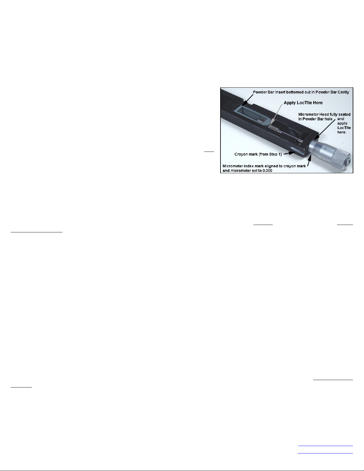
Step 1: Place an Index Mark on Powder Bar
The Auto Powder Measure is oriented differently on each Dillon press. Before
removing the powder bar, decide from which side you will want to view the
micrometer when adjusting the powder charge. As you are facing the press, you will
typically adjust the micrometer from the side shown below.
• Square Deal B – Left Side • XL 650 – Left Side • Super 1050 – Left Side
• RL 550B – Right Side • SL 900 – Right Side • AT 500 – Right Side
Mark a line on that side of the powder bar, near the adjustment screw, with a pencil,
white crayon or other marker that is easily visible but removable. This line will be
used later to orient the micrometer index mark for easy reading. On the XL 650 and
Square Deal B you will notice that the micrometer numbers will be upside-down. But
this orientation will be much easier to see during adjustment than if it was oriented
on the opposite side of the powder bar as with the other presses.
Step 2: Remove Powder Bar
Remove the Powder Bar from the Powder Measure. (Refer to Auto Powder Measure instruction manual for details.)
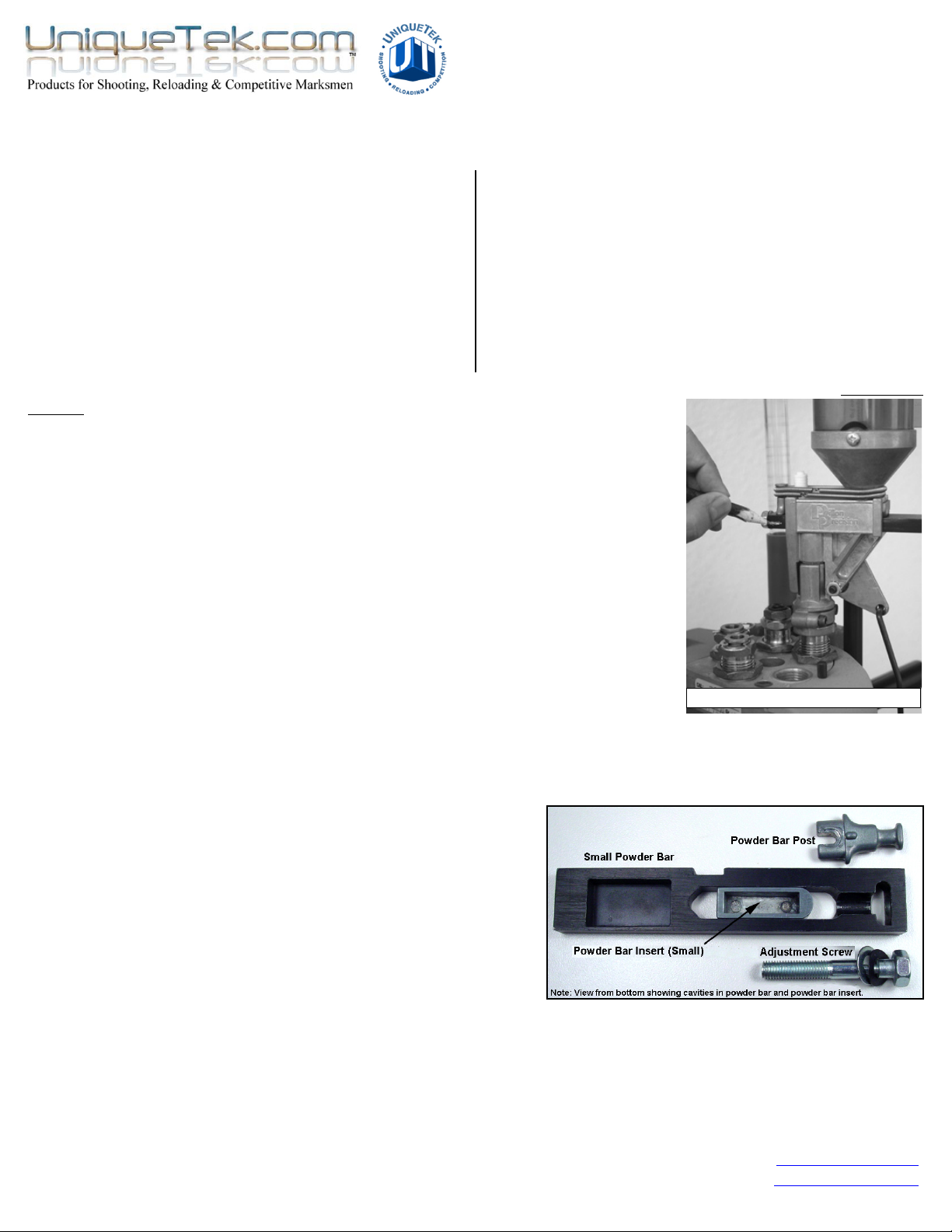
Step 3: Disassemble the Powder Bar
NOTE: Before disassembly, look closely at the Powder Bar and note that Powder Bar Inserts (Ex-Small, Small and
Large) and some Powder Bars (Small and Large) have a flat side and a side with a cavity. The cavities must always
be on the bottom side of the Powder Bar.
a. Remove the Powder Bar Post. Press the bolt head against a
hard surface to compress the spring washer while pulling out
the Powder Bar Post. The Belted Magnum powder bar and
SL900 Shot Bar have a 3/8” set screw instead of a powder bar
post. Remove the set screw using a 3/16” hex key.
b. Remove the Powder Bar Adjustment Screw.
c. Set aside the Powder Bar Adjustment Screw, spring washer
and flat washer. They will no longer be used.
Step 4: Prepare the Powder Bar for Installation **
The Teflon coating must be completely removed from the hole in the end of the powder bar where the adjustment
screw was removed. Use a round file or rolled up sandpaper to scrape away the Teflon coating, leaving a fresh bare
metal surface for the LocTite to achieve a good bond. Clean the hole with rubbing alcohol to remove any residue.
Note: If you happen to have a 7mm thread tap, it does a quick job of cutting through the Teflon coating and exposing clean bare metal for the
Loctite to achieve a solid bond. Only a 7mm tap is the correct size. Do not substitute any other size metric or SAE tap.
** The Belted Magnum powder bar and SL900 Shot Bar adjustment screw hole is smaller than on the other powder bars and must be
enlarged using a 17/64” drill bit before installing the micrometer. Some older Small and Large powder bars may also require enlarging.
Applying index mark (XL-650 shown)

UniqueTek, Inc. 540 W. Iron Ave., Suite 118 web: www.uniquetek.com
Phone: 480-507-0866 Mesa, AZ 85210 e-mail: info@uniquetek.com
Fax: 480-507-0867 - 2 - Rev. 20 04/15
Step 5: Install Micrometer Assembly
NOTE: Do not remove the plastic strip(s) jammed between the micrometer shaft and the threaded bushing. They are
there to provide friction to keep the micrometer setting from drifting during use.
a. Set the micrometer to a reading of 0.000.
b. Place the Powder Bar Insert in the Powder Bar. Make sure to orient the flat sides of the powder bar and powder
bar insert so they are both on the top side of the Powder Bar (photo below shows the bottom side).
c. Hold the Powder Bar vertically with the Powder Bar Insert at the bottom (minimum powder setting) and insert the
micrometer assembly down through the hole in the Powder Bar where the Powder Bar Adjustment Screw was
removed. Screw the ¼-28 adapter bushing into the Powder Bar Insert until the micrometer head is seated against
the end of the Powder Bar.
d. Check that the micrometer is still set to 0.000 and then position it
so the index mark is aligned with the pencil mark you made on the
Powder Bar during Step 1. (DO NOT FORCE)
e. If the Powder Bar Insert does not touch the end of the Powder Bar
cavity or if the micrometer head is not fully seated in the hole, pull
it out slightly and screw the ¼-28 adapter bushing a little more or
less into the Powder Bar Insert. Repeat until the micrometer reads
as close as possible to 0.000 when the Powder Bar Insert just
bottoms out against the end of the Powder Bar cavity.
NOTE: Do not worry if the micrometer does not read exactly 0.000.
The micrometer is only for indexing purposes, so zero is an arbitrary
number. However, it is better if it reads slightly greater than 0.000 rather than below 0.000 when the Powder Bar Insert
bottoms out, so the micrometer setting will always be a positive number. This way you will never accidentally confuse
–0.010 with +0.010. The Micrometer has been designed with more range than is needed so you will still be able to use
the full range of powder bar adjustment.
Step 6: Loctite®Micrometer Assembly Into Place
The micrometer head must be held in place using the LocTite supplied in the kit. Before applying the Loctite, make
absolutely certain that the powder bar is correctly assembled, the micrometer zero is adjusted and the micrometer
head index mark is aligned with the mark you applied to the Powder Bar in Step 1.
Note: Photo in Step 5 also indicates locations for Loctite application.
a. Twist off the top of the Loctite container and attach the application needle.
b. Apply 2 drops of LocTite to the ¼-28 bushing screw threads at the point where they engage the Powder Bar Insert.
Caution: Do not get Loctite on the small #2 screw at the very tip of the micrometer shaft!
c. Lift the micrometer head up 1/8th-inch and apply Loctite directly to the black base where it inserts into the Powder
Bar hole. Apply only enough Loctite to wet the micrometer base all the way around.
DO NOT APPLY TOO MUCH LOCTITE! Excess Loctite can drip down onto the micrometer shaft and seize the
micrometer. Use a cotton swab to remove any excess Loctite then apply a drop of oil to the micrometer shaft to
prevent any remaining Loctite residue from bonding.
d. Set the powder bar where it will be undisturbed while the Loctite cures. Clamp it vertically in a vice, prop it
vertically between heavy books or lay on a flat surface (with the micrometer head hanging off the edge) so that the
Loctite cures with the powder bar insert aligned with the powder bar. You may wish to add weight to hold it tightly
while the Loctite cures. It is important that the powder bar insert is held aligned with the powder bar while the
Loctite cures. Allow 24 hours for the Loctite to fully cure.
Step 7: Reinstall Powder Bar Post
The Powder Bar Post must be filed before installation to eliminate any contact with the micrometer shaft. Use a small
file, emery board or rolled up sand paper to file the inside surfaces of the Powder Bar Post where it touches the
micrometer shaft. This is very soft metal so only a few strokes should be required. There must be absolutely no
contact between the powder bar post and the micrometer shaft.
Note: The new style Dillon Auto Powder Measure (without return springs) does not need a Powder Bar Post after
the micrometer is installed. The setscrew used on the Belted Magnum and SL900 Shot Bar bar is also not needed.
Step 8: Install Micrometer Powder Bar in your Powder Measure.
Install the Micrometer Powder Bar in the Powder Measure by following in reverse the procedures used to disassemble
in Step 2. That is it!

UniqueTek, Inc. 540 W. Iron Ave., Suite 118 web: www.uniquetek.com
Phone: 480-507-0866 Mesa, AZ 85210 e-mail: info@uniquetek.com
Fax: 480-507-0867 - 3 - Rev. 20 04/15
How to Read Micrometer Powder Bar Setting
A micrometer or dial caliper should be on every reloading bench. But some times I get a little rusty if I don’t use my
micrometer frequently. So I’ve included these instructions just as a refresher. The photo below shows the Micrometer
Powder Bar set to a random setting of 0.332.
To read that setting;
1. First, find the largest whole number on the linear
scale. In this case it is 3.
Setting is > 0.3
2. Next, read the subdivisions on the linear scale. Each
sub-division is 0.025. In this case, one sub-division is
visible so add 0.025 to 0.3.
Setting is > 0.325
3. Now read the dial. Each division on the dial is 0.001.
The dial reads 7, so add 0.007 to 0.325.
Final setting = 0.332
That said, you might find it easier to read the settings as if
each whole number on the linear scale is 1.0 instead of 0.1. Reading the micrometer this way, the final setting shown
above is 3.32 instead of 0.332. I personally find it easier to read micrometer powder bar settings if I do it this way. The
“calibration curves” shown on the next page were created reading the micrometer settings this way. Either way will
yield the same results.
It is recommended that adjustments be made to the nearest 0.001 increment and not use settings between the lines
on the dial. This will have no significant impact on powder weight accuracy as the micrometer has much finer screw
threads (40 threads per inch) than the original powder bar adjustment screw (28 threads per inch).
The instructions for the Dillon Auto Powder Measure recommend turning the powder bar adjustment screw in 1/4-turn
increments when adjusting the powder charge. The micrometer has finer screw threads so the equivalent adjustment
is more than 1/4 turn. The equivalent on the micrometer is 0.009 increments on the dial. To keep it simple, we
recommend using 0.010 increments for initial powder charge adjustments and then using smaller increments as you
get close to your desired final powder weight. Also, the micrometer works in reverse compared to the original, powder
bar adjustment screw … turning the micrometer counterclockwise increases the powder charge.
Record the powder weight you obtain at each micrometer setting as you work toward your desired charge weight. This
data can be charted to give you a calibration curve (see page 4) for that particular powder. Using the calibration curve,
you can easily predict the micrometer setting that will yield a particular charge weight. Just dial the micrometer to that
setting and confirm the charge weight by weighing.
CAUTION: You must always confirm the charge weight with a powder scale, even when setting the Micrometer Powder
Bar based on data from your own calibration curve.
NOTE: As when making any powder bar adjustment, throw several “dummy” charges before measuring any. This will
allow the powder to “settle in” to the new powder bar adjustment and give an accurate reading.
NOTE: When changing from a very large to a very small setting, you will compress powder in the powder bar and
potentially overstress the micrometer threads. Cycle the press to drop powder, then make the adjustment while the
press handle is still in the down position. All powder weight changes should be made with the press handle in the
down position so that the powder bar is empty of powder.
Calibration Curves
If you reload a very wide range of charge weights with a particular powder, you can make a calibration curve for that
powder. Once completed, you can dial the micrometer to any charge weight you want by looking up the micrometer
setting from the curve. This will get you very close to the desired charge weight on the first attempt, greatly minimizing
the time needed to “dial in” the exact charge weight.
You can download a copy of the Calibration Curve Spreadsheet from the Micrometer Powder Bar Kit™ page
on our web site at http://www.uniquetek.com/site/696296/product/T1231.
CAUTION: You must always confirm the charge weight with a powder scale, even when setting the Micrometer Powder
Bar based on data from your own calibration curve.

UniqueTek, Inc. 540 W. Iron Ave., Suite 118 web: www.uniquetek.com
Phone: 480-507-0866 Mesa, AZ 85210 e-mail: info@uniquetek.com
Fax: 480-507-0867 - 4 - Rev. 20 04/15
Below is an example “Calibration Curve” for two of my favorite gunpowders. Due to the different physical
characteristics of various powders, you must make a calibration curve for each powder you use. You must also make
separate calibration curves for each powder bar size you use (Ex-Small, Small, Large and Magnum). As described
previously, I find it much easier to read the micrometer as if each major increment were 1.00 instead of 0.100. This
technique, although technically incorrect, makes reading the powder settings more intuitive.
You can look up the micrometer setting for any charge weight directly from your chart. But, if you have a computer and
Microsoft Excel, you can fit a linear curve to the data and get the equation for the curve. From that equation, you will
be able to quickly calculate the micrometer setting of any charge weight you desire!
For example, if I want 6.7 grains of Winchester 231, the equation (from the example calibration curve above) is;
Micrometer Setting = (6.7 –2.7368) ÷ 2.4708 = 1.60
So you don’t need a computer at your reloading bench. Once you have the equation, a hand calculator will do.
CAUTION: You must always confirm the charge weight with a powder scale, even when setting the Micrometer Powder
Bar based on data from your own calibration curve.
Since all calibration curves must be linear, curves can be generated with far fewer measurements (e.g. 0.00, 1.00,
2.00, 3.00, 4.00, 5.00) and still get a reasonably accurate curve with a lot less work. For maximum accuracy over a
short range of powder weights, you can make calibration curves that cover just the range of powder weights you
typically load, and measure at closer spaced micrometer settings. Always include one data point above and below the
maximum and minimum powder weights you will actually use.
CAUTION: The above calibration curves are supplied only as examples. Do not attempt to use them with your own
micrometer powder bar. Due to the slight differences in the zero setting from one Micrometer Powder Bar
installation to another, calibration curves for one Micrometer Powder Bar will yield slightly larger or smaller
powder charges compared to another Micrometer Powder Bar. Thus, if you have more than one Micrometer Powder
Bar of the same size, you must generate separate calibration curves for each one. You may wish to write a number
on the side of each Micrometer Powder Bar so that you can keep track of which set of calibration curves goes with
each Micrometer Powder Bar.
Disclaimer: UniqueTek, Inc. is not liable for damages or personal injury that may be incurred as a result of using this product in an improper way or in a
reloading press that has been improperly maintained or operated. It is your responsibility to ensure that your reloading equipment is properly assembled,
is maintained in proper working condition, and is used according to the manufacturer’s instructions and safe reloading practices.
* Dillon Precision does not authorize the Micrometer Powder Bar Kit™ for use on any of its reloading presses and its use may void manufacturer or
dealer warrantees.
Winchester 231!
"y = 2.4708x + 2.7368 R2= 0.9998"!
Mic Setting = (Grains - 2.7368) ÷ 2.4708!
Vhitavuori N350!
"y = 2.3938x + 2.53 R2= 0.9999"!
Mic. Setting = (Grains - 2.53) ÷ 2.3938!
0.0!
1.0!
2.0!
3.0!
4.0!
5.0!
6.0!
7.0!
8.0!
9.0!
10.0!
11.0!
12.0!
13.0!
14.0!
15.0!
16.0!
17.0!
0.000!
0.250!
0.500!
0.750!
1.000!
1.250!
1.500!
1.750!
2.000!
2.250!
2.500!
2.750!
3.000!
3.250!
3.500!
3.750!
4.000!
4.250!
4.500!
4.750!
5.000!
5.250!
5.500!
Charge Weight (Grains)!
Micrometer Setting!
Calibration Curve for Small Powder Bar !
Winchester 231!
Vihtavuori N350!
This manual suits for next models
5
Table of contents
Popular Measuring Instrument manuals by other brands

AIR SYSTEMS
AIR SYSTEMS CO-91IS operating instructions

Chauvin Arnoux
Chauvin Arnoux C.A 1310 user manual

SOMMER
SOMMER TQ-S Tracer user manual

WIKA
WIKA CPG1500 operating instructions

Transcell Technology
Transcell Technology TI-1680 manual

SATAM
SATAM ZCM17 Description, operation, installation and maintenance manual