Unit UT8805E User manual

English Manua l
UT8805E Benchtop DigitalMu
l t i m e t e r

UT8805E Benchtop Digital Multimeter
2
Preface
Thank you for purchasing the new benchtop digital multimeter. In order to use this product safely and
correctly, please read this manual thoroughly, especially the Safety Information part.
After reading this manual, itis recommended to keepthe manual at an easily accessible place,preferably
close to the device, for future reference.
Copyright Information
Copyright
Uni-Trend Technology (China) Co., Ltd. all rights reserved.
Trade Mark
UNI-T is the registered trademark of Uni-Trend Technology (China) Co., Ltd.
Declaration
UNI-T products are protected by patent rights in China and other countries, including issued and
pending patents.
Uni-Trend reserves the rights to any product specification and pricing changes.
Uni-Trend reserves all rights.Informationin thismanual supersedes all previously published versions.
No part of this manual may be copied, extracted or translated by any means without the prior
permission of Uni-Trend.

UT8805E Benchtop Digital Multimeter
3
General Safety Overview
This instrument strictly complies with safety standards of IEC61010-1, EN61010-2-030, pollution level II,
over voltage CATI 1000V, CAT II 300V and double insulated during design and manufacturing. It is IP65
waterproof and dustproof. In case the meter is not used properly as instructions, the protection provided
may be weakened or lost.
Please use the dedicated UNI-T power supply wire appointed to the local region or country for this
product, and check if there is any metal part exposed or insulating layer damage.
This product is grounded through the power supply ground wire. To avoid electric shock, grounding
conductors must be connected to the ground. Please be sure that the product is properly grounded
before connecting to the input or output of the product. The signal ground wire of the rear panel is the
same as the ground potential.
Please check the accessories and wires for any mechanical damage before usage. Please replace
the wire before use if it is damaged.
Please notice rated operating range and product marks. Never input over-range voltage into any
terminal or ground point of this product.
When measuring, do not touch any exposed wires, connectors, unused inputs or the circuits being
measured. When measuring the voltage higher than 60V (DC) or 30V (AC), keep your fingers behind
the finger guard ring of the test leads to prevent electric shock.
Do not operate the product if you suspect it is faulty, and please contact UNI-T authorized service
personnel for inspection. To avoid injury and damage, only trained personnel can perform the
maintenance program.
Never touch exposed joints and components after connecting the power supply.
Please do not operate the product when the instrument box opens. Do not change the internal circuit
of the meter.
Only use fuse that appointed to this product.
Use appropriate overvoltage protection to ensure that there is no overvoltage (like caused by lightning),
otherwise it may cause electric shock.
Do not use or store the meter in high temperature, high humidity, flammable, explosive and strong
magnetic field environments.
Before measuring resistance, continuity, diode and capacitors, please disconnect the power and fully
discharge all high-voltage capacitors.

UT8805E Benchtop Digital Multimeter
4
Limit Protection of Input Terminal:
1) Main input terminal HI and LO
The input terminals HI and LO apply to voltage, resistance, capacitance, continuity, frequency and diode
measurements.
a. HI-LO limit protection: the HI-LO limit is maximum 1000V DC or 750V AC voltage, which can also be
expressed as maximum 1000Vpk.
b. LO-GND limit protection: the limit of input terminal LO-GND can safely float to 500Vpk. The limit of
the terminal HI-GND is maximum 1000Vpk. Therefore, the sum of floating voltage and measured
voltage shall less than 1000Vpk.
2) Sampling terminals Sense HI and LO sense
Terminal Sense HI and LO sense are used for 4-wire resistance measurement.
a. The limit protection of Sense HI-LO sense is 200Vpk.
b. The limit protection of LO sense-LO is 2Vpk.
3) Current input terminals mA and A
a. The terminal mA and terminal LO are used for current measurement below 200mA. The fuse on rear
panel provides a maximum current limit protection 250mA for mA terminal.
b. The terminal A and terminal LO are used for current measurement from 200mA to 10A. The fuse on
rear panel provides a maximum current limit protection 10A for terminal A.
Note: the voltage of the current input terminal is similar to that of terminal LO. To maintain good
protection, only the specified type and class fuses can be replaced.
IEC Measurement Category II Overvoltage Protection
To avoid shock hazards, UT8805E provides overvoltage protection for mains connections that meet both
conditions below.
1. The input terminals HI and LO are connected to the mains under the measurement class II condition
(described below).
2. The maximum voltage of the mains is 300V AC.
WARNING: IEC measurement category II includes electrical devices connected to mains by a socket on
a branch circuit, such as most small appliances and measuring instruments. UT8805E can apply to make
following measurements: input terminals HI and LO are connected to the mains of IEC measurement
category IIdevices (maximum 300V AC) or are connected to branch outlets. However, the input terminals
HI and LO cannot be connected to the mains of permanently installed electrical device, such as the
distributor of main circuit breaker, the cut-out box of sub-distributor, or the permanently connected motor,
because these devices and circuits are prone to be overvoltage.
CAUTION: voltages above 300V AC can only be measured in circuits that disconnected from the mains.
However, transient overvoltage also exists in this kind of circuits. UT8805E can safely withstand
accidental transient overvoltage up to 2500Vpk. Do not use the device to measure circuits if the transient
overvoltage may exceed this range.

UT8805E Benchtop Digital Multimeter
5
Safety Terms and Symbols
Terms in the manual --- Following terms may appear in this manual:
Warning: a Warning specifies conditions and actions that may pose hazards to the user.
Caution: a Caution identifies conditions and actions that may cause damage to the product or other
properties.
The CAT I (1000V)
IEC measurement category I. The maximum measurable voltage at terminal HI-LO is 1000Vpk
The CAT II (300V)
IEC measurement category II. In the case of class II overvoltage, the input may be connected to the
mains (up to 300V AC)
Terms on the product --- Following terms may show on the product:
DANGER indicates any injury hazard immediately accessible as you read the marking.
WARNING indicates any injury hazard not immediately accessible as you read the marking.
CAUTION indicates any damage may happen to the product or other properties
Symbols on the product --- Following symbols may show on the product:
Caution, possibility of electric shock
Warning or Caution
Protective conductor terminal
Ground terminal for chassis
Earth (ground) terminal

UT8805E Benchtop Digital Multimeter
6
Overview
UT8805E is a 200000 count benchtop digital multimeter with high precision, multi-function and full-
automatic functions of mathematical operations, capacitance, temperature and other basic
measurements.
UT8805E comes with 4.3-inch 480*272 TFT display, supports LAN, USB, RS-232C and GPIB (optional)
operations, which makes it a great laboratory instrument and a precise measurement tool for automated
test systems.
Features:
200000 count resolution
Measuring speed: 2.5/10/5k reading per second
Dual display
200mV~1000V DC voltage range
200μA~10A DC current range
True-RMS,200mV~750VAC voltage range
True-RMS,2mA~10AAC current range
200Ω~100MΩ resistance range 2-line and 4-line resistance measurement
2nF~2000μF capacitance range
20Hz~1MHz frequency range
Continuity and diode test
Temperature measurement with built-in thermocouple cold junction compensation
Various mathematic operations: maximum, minimum, average value, standard deviation, pass/fail,
dBm, dB, relative measurement, histogram, trend chart, bar chart
USB drive store data and configuration
Supports interface of USB, GPIB, RS-232C and LAN, USB-TMC, IEEE 488.2 standard, VXI11 and
SCPI language
The latest mainstream multimeter SCPI command set compatible
History data record and storage
1GB NAND FLASH storage, mass storage system and test data
Chinese & English menu and online help system
PC control software of upper computer
Supports global mains voltage

UT8805E Benchtop Digital Multimeter
7
Table of Contents
Preface----------------------------------------------------------------------------------------------------------------------------------------2
Copyright Information---------------------------------------------------------------------------------------------------------------------2
Safety Terms and Symbols-------------------------------------------------------------------------------------------------------------5
Overview--------------------------------------------------------------------------------------------------------------------------------------6
Chapter 1 Quick start---------------------------------------------------------------------------------------------------------------------9
1.1 General Checking......................................................................................................................... 9
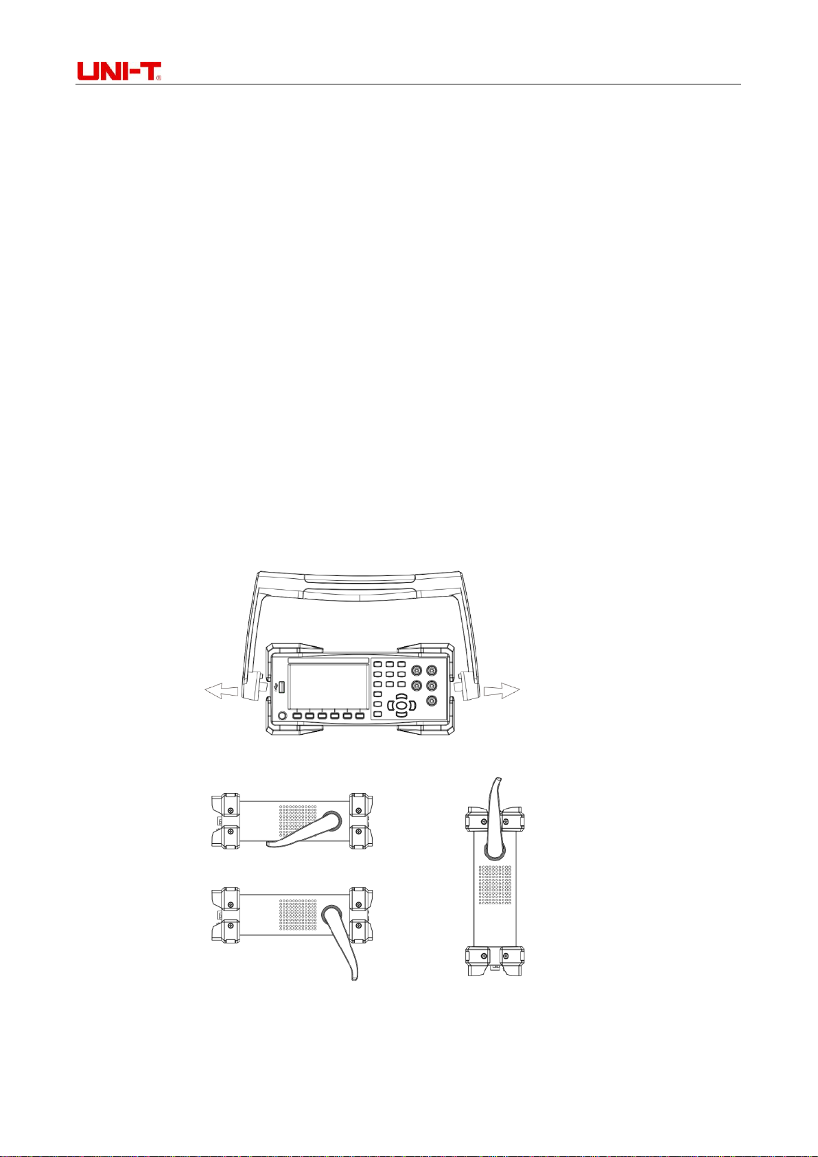
1.2 Handle Adjustment........................................................................................................................ 9
1.3 Front Panel.................................................................................................................................. 10
1.4 Rear Panel.................................................................................................................................. 10
1.5 Power On.....................................................................................................................................11
1.6 User Interface ..............................................................................................................................11
Chapter 2 Panel Operation-----------------------------------------------------------------------------------------------------------12
2.1 Range Selection.......................................................................................................................... 12
2.2 Reading Speed Selection........................................................................................................... 14
2.3 Basic Measurements .................................................................................................................. 14
2.3.1 DC Voltage Measurement................................................................................................ 14
2.3.2 DC Current Measurement ................................................................................................ 16
2.3.3 AC Voltage Measurement................................................................................................. 17
2.3.4 AC Current Measurement................................................................................................. 18
2.3.5 2-wire/4-wire Resistance Measurement........................................................................... 19
2.3.6 Frequency Measurement.................................................................................................. 21
2.3.7 Signal Cycle Measurement............................................................................................... 22
2.3.8 Continuity Test.................................................................................................................. 23
2.3.9 Diode Measurement......................................................................................................... 24
2.3.10 Temperature Measurement ............................................................................................ 25
2.4 Relative Measurement Parameters....................................................................................... 27
2.4.1 DC Input Impedance......................................................................................................... 27
2.4.2 Short- circuit Resistance................................................................................................... 27
2.4.3 Dual Display Function....................................................................................................... 28
2.5 Auxiliary System Functions ....................................................................................................... 28
2.5.1 I/O Configuration............................................................................................................... 29
2.5.2 System Settings................................................................................................................ 30
2.5.3 Time Setting...................................................................................................................... 31
2.5.4 Firmware Upgrade............................................................................................................ 31
2.6 Samples Acquirement Setting ................................................................................................... 32
2.6.1 Auto Trigger ...................................................................................................................... 32
2.6.2 Single Trigger.................................................................................................................... 32
2.6.3 External Trigger ................................................................................................................ 33
2.7 Help System................................................................................................................................ 34
2.8 Mathematical Functions.............................................................................................................. 35
2.8.1 Statistics Operation .......................................................................................................... 36
2.8.2 Limit Operation ................................................................................................................. 37

UT8805E Benchtop Digital Multimeter
8
2.8.3 The dBm Operation.......................................................................................................... 38
2.8.4 dB Operation..................................................................................................................... 38
2.8.5 The Relative Operation..................................................................................................... 39
2.9 Display Format........................................................................................................................... 40
2.9.1 Number............................................................................................................................. 40
2.9.2 Bar Chart .......................................................................................................................... 40
2.9.3 Trend Chart....................................................................................................................... 41
2.9.4 Histogram ......................................................................................................................... 41
2.9.5 Enabled trigger ................................................................................................................. 43
2.9.6 Auto Trigger ...................................................................................................................... 43
2.9.7 Single Trigger.................................................................................................................... 43
2.9.8 Hold Measurement ........................................................................................................... 43
2.9.9 Storage Management....................................................................................................... 43
Chapter 3 Practical Cases------------------------------------------------------------------------------------------------------------------44
3.1 Readings Statistics ..................................................................................................................... 44
3.2 Elimination of Test Leads Impedance Error................................................................................ 45
3.3 DBm Measurement..................................................................................................................... 45
3.4 dB Measurement......................................................................................................................... 46
3.5 Limit Test..................................................................................................................................... 46
3.6 Hold Measurement...................................................................................................................... 47
3.7 Thermocouple Setting and Measurement .................................................................................. 47
Chapter 4 Measurement Guide--------------------------------------------------------------------------------------------------- 49
4.1 True RMS AC Measurement....................................................................................................... 49
4.2 Crest Factor Error (Non-sinusoidal Input)................................................................................... 49
4.3 Load Error (AC Voltage) ............................................................................................................. 50
Chapter 5 Trouble Shooting-----------------------------------------------------------------------------------------------------------51
Chapter 6 Appendix----------------------------------------------------------------------------------------------------------------------52
Appendix A: Accessories of UT8805E.............................................................................................. 52
Appendix B: Warranty....................................................................................................................... 52
Appendix C: Maintenance and Cleaning.......................................................................................... 52
Appendix D: Contacts....................................................................................................................... 52

UT8805E Benchtop Digital Multimeter
9
Chapter 1 Quick start
This chapteris a simple guide of preparation before using, the front/real panel and interfaces ofUT8805E
digital multimeter.
1.1 General Checking
1) Checking for any damage in transit
Keep the package if the packing carton or foamed plastic cushion is seriously damaged, until the
multimeter and accessories pass the electric and mechanical inspections. Contact distributor or local
representative office immediately if any abnormality is found.
2) Accessories checking
The accessories list is provided in appendix Aof chapter 6. User can check refer to this list. Contact
distributor or local representative office immediately if any accessory is missing or damaged.
3) Complete instrument checking
Contact distributor or local representative office immediately if any abnormal operation or
appearance damage is found.
1.2 Handle Adjustment
To adjust the handle of multimeter, please hold the handle by both sides, pull outward, and rotate it as
needed, see Figure 1-1 and 1-2.
Figure 1-1 Handle adjustment
Figure 1-2 Lying position Figure 1-3 Moving position

UT8805E Benchtop Digital Multimeter
10
1.3 Front Panel
UT8805E comes with a simple clear front panel, its controlling buttons are designed by logic and can be
easily found to make basic operation. See Figure1-4.
Figure 1-4 Front panel
[A] LCD display
[E] Measure and auxiliary function buttons
[B] USB Host interface
[F] Range selector and direction buttons
[C] Power switch
[G] Input interfaces
[D] Menu operating buttons
1.4 Rear Panel
Various interface are provided by UT8805E, includes USB Device, RS-232C, LAN, GPIB (optional) and
so on, as shown in figure:
Figure 1-5 Rear panel
[A] Current measurement fuse
[G] LAN interface
[B] Lockhole
[H]AC voltage selector
[C] VMC output
[I] RS-232C interface
[D] External trigger input
[J] Power supply interface
[E] GPIB interface
[K] Power supply fuse
[F] USB Device interface
[L] Power switch

UT8805E Benchtop Digital Multimeter
11
Operating menu
1.5 Power On
Please follow these steps to power on the multimeter:
1) According to local power supply standard, adjust the AC voltage selector to be 100(100~110V,
45~440Hz, AC), 120(110~132V, 45~440Hz, AC), 220(200~240V, 45~66Hz, AC), or 240(216~264V,
45~66Hz,AC).
2) Connect the multimeter withAC current by random power line.
3) Observe the power indicator on front panel turns red.
4) Long press the power button for a few second till the multimeter displays picture.
Note: the items in [ ] are F1-F6 soft key menu items.
1.6 User Interface
Single screen:
Figure 1-6 Interface of single screen mode
Dual screen:
Figure 1-7 Interface of dual screen mode
Trigger method
Range
Current
measuring
function
Unit
Reading
Main screen
Second screen
Current
Measuring
function

UT8805E Benchtop Digital Multimeter
12
Chapter 2 Panel Operation
DC voltage/current measurement
AC voltage/current measurement
2/4-wire resistance measurement
Capacitance/temperature measurement
Continuity/diodes measurement
Frequency/period measurement
Dual display or auxiliary system utility
Acquire setting or help system
Mathematical operation or save
Run/stop/exit function
Manual trigger or hold function
Shift function switch
Auto/manual range selector
Range selector and direction buttons
Menu operating buttons
Power switch
2.1 Range Selection
Bothautorange and manual rangecan be selected.Themultimetercan automaticallyselectproper range
according to the input signal, so that the input value is just between 10% and 110% of the range

UT8805E Benchtop Digital Multimeter
13
conveniently. Users can also choose ranges manually for faster readings and results. The range selector
is located on the right side of the front panel as Figure 2-1.
Figure 2-1 Front panel range select button
Method 1: select ranges by range selector on front panel.
Auto range: press button to switch between auto/manual ranges
Manual range: press button to increase the range, and press button to decrease.
Method 2: select ranges by soft key menu in main interface, as Figure 2-2.
Auto range: press [auto] to select auto range and disable the manual range
Manual range: press [200mV], [2V], [20V], [200V] or [1000V]. Take DC voltage measurement as an
example, set proper range manually, and auto range is disabled.
Figure 2-2 Range selecting menu
Note:
1) The overload symbol –OL will be shown if the input signal is over range.
2) All scales except DCV 1000V and ACV 750V are allowed to exceed the range by 20%.
3) When the instrument is powered on, remotely reset and started with the factory settings, auto range
is selected by default.
4) It is suggested that users should choose auto range in case of unpredictable measuring range to
protect the instrument and obtain accurate data.
5) For the dual display function, the ranges of both screens are similar and cannot be changed
separately.
6) The ranges are fixed in continuity/diode measurement, which is 2kΩ for continuity measurement,
and 4V for diode.
7) Particularly, the maximum range of the input terminal mAis 200mA(including DCI andACI, the same
as following ranges). The input terminal Ais used for ranges of 2A and 10A. Therefore, current over
200mA shall be input by terminal A, and current below 200mA shall be input by terminal mA. There
is no automatic switching between two different current input terminals.
8) In current measurement, overcurrent protection is provided by two fuses.
9) Voltage measurement shall not be overloaded for a long period to avoid circuit damage.
Increase range, and disable auto range
Decrease range, and disable auto range
Auto range

UT8805E Benchtop Digital Multimeter
14
2.2 Reading Speed Selection
There are 3 reading speeds can be selected by soft key menu: [Slow] 2.5 reading/s, [Medium] 10
reading/s and [Fast] 5k reading/s. The display refreshing rate is 10 times/s. Press [Speed] button, and
then select [Slow], [Medium] or [Fast] to select measuring speed.
Figure 2-3 Interface of measuring speed selecting
Note:
1) There are 3 reading speeds (slow, medium and fast) can be set in DCV, DCI and 2W/4W resistance
functions.
2) In slow speed measurement, the zero reading function of DCV, DCI and 2W/4W resistance is on,
which can restrain thermo-electromotive force and offset voltage/current caused by temperature
variation and component aging.
3) 2.5 reading/s and 10 reading/s are corresponding to 5.5 bits reading resolution.
4) 5k reading/s is corresponding to 5.5 bits reading resolution.
5) Temperature measurement is corresponding to 5.5 bits reading resolution (slow speed).
6) Diode/continuity measurement is corresponding to 4.5 bits reading resolution (medium speed).
7) Frequency measurement is corresponding to 5.5 bits reading resolution, and the reading speed
depends on the input signal frequency.
8) Capacitance measurement is corresponding to 3.5 bits reading resolution, and the reading speed
depends on the charge-discharge time of capacitor.
2.3 Basic Measurements
The basic measurement functions of UT8805E include measurements ofDC/AC voltage, DC/AC current,
2/4-wire resistance, capacitance, continuity, diode, frequency/cycle and temperature.
2.3.1 DC Voltage Measurement
The maximum DC voltage range of UT8805E is 1000V, and DC voltage measurement is selected by
default. The connecting methods and operation are introduced below.
Steps:
1) Press button to enter interface of DC voltage measurement as Figure 2-4.

UT8805E Benchtop Digital Multimeter
15
Figure 2-4 Interface of DC voltage measurement
2) Connect test leads to the measured voltage as Figure 2-5, red test lead should be connected to
terminal HI, and the black one to terminal LO.
Figure 2-5 Connection of DC voltage measurement
3) Select proper range according to input DC voltage.
Range
200mV, 2V, 20V, 200V, 1000V
Input protection
DC 1000V orAC 750Vrms (terminal HI) for all ranges
Configurable
parameters
Range, input impedance, reading speed, relative operation set
value
Note:
Except for 1000V, all ranges are allowed to exceed range by 20%.
In 1000V range, OL will show if input voltage exceeds 1050V.
1000V input protection is provided in arbitrary ranges.
4) DC input impedance setting (only for scales of 20V and below)
There are two options of input impedance: [Auto] and [10M]. For scales of 20V and below, [Auto] means
the input impedance is over 10GΩ, otherwise the input impedance is 10MΩ.
5) Relative value setting
Turn the relative operation on, the displayed value is actual measured value minus the set relative value.
About relative value setting, please refer to 2.10 Mathematical Functions.
6) Reading speed
Press [Speed] to select proper reading speed during measurement.
7) History data review
User can check the history data by number, bar chart, trend chart, and histogram.
Note: when the input terminal is in dangling state (no voltage input), random reading between ±20V will

UT8805E Benchtop Digital Multimeter
16
show.
2.3.2 DC Current Measurement
The maximum DC current range of UT8805E is 10A. The connecting and measurement methods are
shown below:
Steps:
1) Press button, then press button again to enter DC current measuring interface, as figure
shown:
Figure 2-6 Interface of DC current measuring
2) Connect the multimeter to the circuit as Figure 2-7. When the current is <200mA, connect the red
test lead to terminal mAand connect the black one to terminal Input-LO;When the current is 200mA-10A,
connect the red test lead to the terminalA and connect the black one to terminal Input-LO.
Figure 2-7 Connection of DC voltage measurement
3) Select proper range according to input current.
Range
200μA, 2mA, 20mA, 200mA, 2A, 10A
Input protection
250mA overcurrent protection for ≤ 200mA range (rear panel);
10Abuilt-inovercurrentprotectionfor the rangesof2Aand10A.
Configurable parameters
Range, reading speed, relative operation set value
Note: Except for 10A, all ranges are allowed to exceed range by 20%.
4) Relative value setting
Turn the relative operation on, displayed value is actual measured value minus the set relative value.
About relative value setting, please refer to 2.10 Mathematical Functions.
5) Measured value reading
Press [Speed] to select proper reading speed during measurement.
6) History data review
User can check the history data by number, bar chart, trend chart, and histogram.

UT8805E Benchtop Digital Multimeter
17
2.3.3 AC Voltage Measurement
The maximum AC voltage range of UT8805E is 750V. The connecting and measurement methods are
shown below:
Steps:
1) Press button to enter the interface ofAC voltage measurement as Figure 2-8:
Figure 2-8 Interface of AC voltage measurement
2) Connect the test leads to the measured voltage as Figure 2-9, connect the red test lead to terminal
HI, and connect the black one to terminal LO.
Figure 2-9 Connection of AC voltage measurement
3) Select proper range according to the input AC voltage.
Range
200mV, 2V, 20V, 200V, 750V
Input protection
DC 1000V orAC 750Vrms (terminal HI) for all ranges
Configurable parameters
Range, reading speed, relative operation set value
Note:
Except for 750V, all ranges are allowed to exceed range by 20%.
In 750V range, OL shows when input exceeds 787V.
750Vrms input protection is provided in arbitrary ranges.
4) Relative value setting
Turn relative operation on, the displayed value is actual measured value minus the set relative value.
About relative value setting, please refer to 2.10 Mathematical Functions.
5) Measured value reading
Press button to obtain the frequency value of measured signal as Figure 2-10.

UT8805E Benchtop Digital Multimeter
18
Figure 2-10 Interface of AC voltage and frequency measurement
6) History data review
User can check the history data by number, bar chart, trend chart, and histogram.
2.3.4 AC Current Measurement
The maximum AC current range of UT8805E is 10A. The connecting and measurement methods are
shown below:
Steps:
1) Press button and press button to enter interface ofAC current measurement as Figure 2-11.
Figure 2-11 Interface of AC voltage measuring
2) Connect the multimeter to the measured circuit as Figure 2-12. When the current is <200mA, the red
test lead should be connected to terminal mA while the black one should be connected to terminal
Input-LO. When the current is 200mA-10A, connect the red test lead to terminal A, and connect the
black one to terminal Input-LO.
Figure 2-12 Connection of AC current measurement
3) Select proper range according to the input current.
Range
20mA, 200mA, 2A, 10A
Input protection
250mA overcurrent protection for the ranges of 200mA and
below (rear panel); 10A built-in overcurrent protection for the
ranges of 2A and 10A.
Configurable
Range, reading speed, relative operation set value

UT8805E Benchtop Digital Multimeter
19
parameters
Note: Except for 10A, all ranges are allowed to exceed range by 20%.
4) Relative value setting
Turn the relative operation on, the displayed value is actual measured value minus the set relative value.
About relative value setting, please refer to 2.10 Mathematical Functions.
5) Measured value reading
If the current value is big enough, press button to obtain the frequency value of measured signal.
6) History data review
User can check the history data by number, bar chart, trend chart, and histogram.
2.3.5 2-wire/4-wire Resistance Measurement
Both the 2-wire/4-wire resistance measurement modes are provided by UT8805E. The connecting and
measurement methods are shown below:
A. 2-wire Resistance Measurement
Steps:
1) Press button to enter interface of 2-wire resistance measurement as Figure 2-13.
Figure 2-13 Interface 2-wire resistance measurement
2) Connect the test leads to the measured resistance as Figure 2-14, connect the red test lead to
terminal HI, and the black one to terminal LO.
Figure 2-14 Connection of 2-wire resistance measurement
3) Select proper current range according to the input resistance.
Range
200Ω, 2kΩ, 20kΩ, 200kΩ, 2MΩ, 10MΩ,100MΩ
Open circuit voltage
<8V
Input protection
DC 1000V orAC 750Vrms (terminal HI) for all ranges
Configurable
parameters
Range, reading speed, relative operation set value

UT8805E Benchtop Digital Multimeter
20
Note: all ranges are allowed to exceed range by 20%.
4) Relative value setting
Turn the relative operation on, the displayed value isthe actual measured value minus the setting relative
value.About relative value setting, please refer to 2.10 Mathematical Functions.
5) Measured value reading
Press [Speed] to select proper reading speed and read the measured value.
6) History data review
User can check the history data by number, bar chart, trend chart, and histogram.
Note: Relative operation is recommended in low resistance measurement, which can eliminate test lead
impedance error.
B. 4-wire Resistance Measurement
When the measured resistance is low, error will be caused by test lead resistance and contact resistance
in circuit. Therefore, 4-wire measuring mode is necessary for a precise measurement.
Steps:
1) Press button, and then press button to enter interface of 4-wire resistance measurement,
as Figure 2-15.
Figure 2-15 Interface of 4-wire resistance measurement
2) Connect the test leads to the measured resistance as Figure 2-16, connect the red test lead to
terminal HI, and the black one to terminal LO. The testleads above areconstant current source output
circuits. Connect the red test leads to terminal Sense HI, and the black one to terminal Sense LO,
and these 2 test leads are voltage gauging circuits.
Figure 2-16 Connection of 4-wire resistance measurement
3) Select proper current range according to the input resistance.
Range
200Ω, 2kΩ, 20kΩ, 200kΩ, 2MΩ, 10MΩ,100MΩ
Table of contents
Other Unit Multimeter manuals