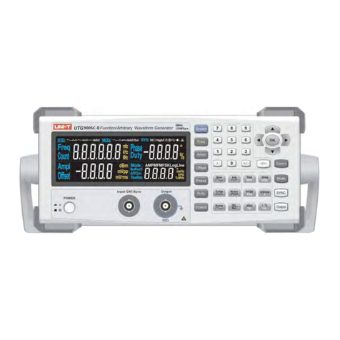
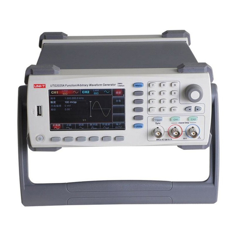
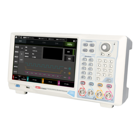
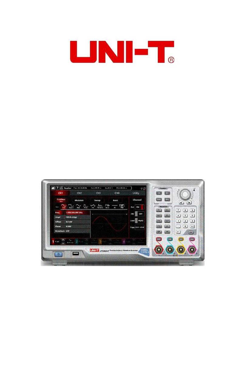
Unit UTG4000A User manual

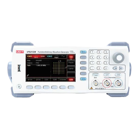
UTG4000A
Function/Arbitrary
Waveform Generator
Quick Guide

UTG4000A Operating Manual
Introduction
Dear Users:
Hello! Thank you for choosing this brand new UNI-T device. In order to safely and
correctly use this instrument, please read this manual thoroughly, especially the Safety
Notes part.
After reading this manual, it is recommended to keep the manual at an easily
accessible place, preferably close to the device, for future reference.
1

UTG4000A Operating Manual
Copyright Information
● UNl-T Uni-Trend Technology (China) Limited. All rights reserved.
Trademark Information
● UNI-T is the registered trademark of Uni-Trend Technology (China) Limited.
Document Version
UTG4000A-20160618-EN-V1.2
Statement
● UNI-T products are protected by patent rights in China and foreign countries,
including issued and pending patents.
● UNI-T reserves the rights to any product specification and pricing changes.
● UNI-T reserves all rights. Licensed software products are properties of Uni-Trend and
its subsidiaries or suppliers, which are protected by national copyright laws and international
treaty provisions.
● Information in this manual supercedes all previously published versions.
2

UTG4000A Operating Manual
Warranty
UNI-T warrants that the product will be free from defects for a three-year period. If the
product is re-sold, the warranty period will be from the date of the original purchase from an
authorized UNI-T distributor. Probes, other accessories, and fuses are not included in this
warranty.
If the product is proved to be defective within the warranty period, UNI-T reserves the
rights to either repair the defective product without charging of parts and labor, or exchange
the defected product to a working equivalent product. Replacement parts and products may
be brand new, or perform at the same specifications as brand new products. All replacement
parts, modules, and products become the property of UNI-T.
The “customer” refers to the individual or entity that is declared in the guarantee. In order to
obtain the warranty service, "customer" must inform the defects within the applicable warranty
period to UNI-T, and to perform appropriate arrangements for the warranty service. The customer
shall be responsible for packing and shipping the defective products to the designated maintenance
center of UNI-T, pay the shipping cost, and provide a copy of the purchase receipt of the original
purchaser. If the product is shipped domestically to the location of the UNI-T service center,
UNI-T shall pay the return shipping fee. If the product is sent to any other location, the customer
shall be responsible for all shipping, duties, taxes, and any other expenses.
This warranty shall not apply to any defects or damages caused by accidental, machine
parts’ wear and tear, improper use, and improper or lack of maintenance. UNI-T under the
provisions of this warranty has no obligation to provide the following services:
a) Any repair damage caused by the installation, repair, or maintenance of the product
by non UNI-T service representatives.
b) Any repair damage caused by improper use or connection to an incompatible device.
c) Any damage or malfunction caused by the use of a power source which does not
conform to the requirements of this manual.
d) Any maintenance on altered or integrated products (if such alteration or integration
leads to an increase in time or difficulty of product maintenance).
This warranty written by UNI-T for this product, and it is used to substitute any other
express or implied warranties. UNI-T and its distributors do not offer any implied warranties
for merchantability or applicability purposes.
For violation of this guarantee, UNI-T is responsible for the repair or replacement of
defective products is the only remedy available to customers. Regardless of whether UNI-T and
its distributors are informed that any indirect, special, incidental, or consequential damage may
occur, the UNI-T and its distributors shall not be responsible for any of the damages.
3

UTG4000A Operating Manual
Table of Contents
Chapter 1 Safety Information -------------------------------------------------------------------------5
1.1 Safety Terms and Symbols ----------------------------------------------------------------5
1.2 General Safety Overview ----------------------------------------------------------------6
Chapter 2 Quick Start -----------------------------------------------------------------------------------7
2.1 General Inspection---------------------------------------------------------------------------7
2.1.1 Inspect Whether Damage is Caused by Transportation -------------------7
2.1.2 Inspect Accessories ----------------------------------------------------------------7
2.1.3 Inspect Complete Machine -------------------------------------------------------7
2.2.1 Introduction of Panels and Keys -------------------------------------------------7
2.2.2 Front Panel --------------------------------------------------------------------------7
2.2.3 Function Interface -------------------------------------------------------------------8
2.2.4 Back Panel ----------------------------------------------------------------------------9
2.3.1 Output Basic Waveform -----------------------------------------------------------9
2.3.2 Set Output Frequency -------------------------------------------------------------9
2.3.3 Set Output Amplitude -------------------------------------------------------------10
2.3.4 Set DC Offset Voltage ------------------------------------------------------------11
2.3.5 Set Pulse Wave --------------------------------------------------------------------12
2.4 Frequency Measurement ----------------------------------------------------------------13
Chapter 3 Advanced Applications ------------------------------------------------------------------14
3.1 Output Modulation Waveform-----------------------------------------------------------14
3.2 Output Arbitrary Wave --------------------------------------------------------------------23
3.2.1 Use Arbitrary Wave Function ---------------------------------------------------23
3.2.2 Point-by-point Output/Play Mode ----------------------------------------------23
3.2.3 Select Arbitrary Wave ------------------------------------------------------------24
3.2.4 Create and Edit Arbitrary Waveform ------------------------------------------24
3.2.5 Output Digital Protocol Coding -------------------------------------------------24
3.3 Function of Digital Arbitrary Wave -----------------------------------------------------35
Chapter 4 Fault Handling -----------------------------------------------------------------------------42
4.1 No Display on Screen (Blank Screen) -------------------------------------------------42
4.2 No Waveform Output ---------------------------------------------------------------------42
4.3 Fail to Correctly Recognize U Disk ----------------------------------------------------42
4

UTG4000A Operating Manual
Chapter 1 Safety Information
1.1 Safety Terms and Symbols
The following terms may appear in this quick guide:
Warning: The conditions and behaviors may endanger life.
Caution: The conditions and behaviors may cause damage to the product and other
properties.
The following terms may appear on the product:
Danger: Performing this operation may cause immediate damage to the operator.
Warning: This operation may cause potential damage to the operator.
Caution: This operation may cause damage to the product and devices connected to
the product.
The following symbols may appear on the product:
AC Electricity
Measurement ground terminal
Housing ground terminal
ON/OFF
High voltage hazard
Caution: please refer to the manual
Protective ground terminal
CE is registered trademark of EU
C-tick is registered trademark of Spectrum Management Agency of Australia.
It indicates conformity with provisions of Australian EMC Framework formulated
according to terms of Wireless Communication Act in 1992.
Containing at least one of six harmful substances that exceed maximum
concentration value (MCV) and environment-friendly usage period (EPUP) of 40
years.
5

UTG4000A Operating Manual
1.2 General Safety Overview
This instrument is designed and produced in strict accordance with GB4793 Safety
Requirements for Electronic Measuring Apparatus and IEC61010-1 safety standard, up to
insulation and overvoltage standard CAT II 300V and safety standard for level-II pollution.
Please read the following preventive safety measures:
● In order to prevent electric shock or fire, please use power line and adapter
dedicated to this product and approved by the country.
● This product is grounded through protective ground lead in the power line. In order
to prevent electric shock, please check whether the power socket to be used for the product
is grounded. Please ensure that the protective ground terminal of the product is reliably
connected to the ground terminal of power line before connecting any input or output terminal
other than power line.
● To avoid personal injury and prevent damage to the product or any product
connected to the product. In order to avoid possible danger, the product can only be used in
the specified scope. Only personnel that have received professional training can execute
maintenance procedures.
● In order to prevent fire or electric shock, please pay attention to all rated values and
signs of the product. Please read the user manual to further understand information about
rated value.
● Don’t use input voltage above rated value of the instrument.
● Inspect whether accessories suffer from mechanical damage before use. If so,
please replace them.
● Only accessories provided for the product can be used. Please don’t use
accessories that are damaged.
● Don’t insert metal objects into input or output terminal of the product.
● If you suspect the product is damaged, please ask qualified maintenance
personnel for inspection.
● Please don’t put the product into operation when crate is opened.
● Please don’t operate in humid environment.
● Please don’t operate in inflammable and explosive environment.
● Keep the surface of product clean and dry.
6

UTG4000A Operating Manual
Chapter 2 Quick Start
2.1 General Inspection
When you get a new function/arbitrary waveform generator, you are advised to inspect
the instrument according to the following steps.
2.1.1 Inspect Whether Damage is Caused by Transportation
If the packaging box or foamed plastic supplementary mat is seriously damaged, please
contact with dealer of the product or local office.
If the instrument is damaged during transportation, please keep the package, and notify
transportation department and dealer of the product, who will arrange repair or replacement.
2.1.2 Inspect Accessories
UTG4000A accessories include power line (applicable to the destination country/region), a
USB data transmission line, two BNC cables (1m), a user CD and a product warranty card.
In case of lack or damage of accessories, please contact with dealer of the product or
local office.
2.1.3 Inspect Complete Machine
If appearance of the instrument is damaged, the instrument runs abnormally or fails to
pass performance test, please contact with dealer of the product or local office.
2.2.1 Introduction of Panels and Keys
2.2.2 Front Panel
Function/arbitrary waveform generator of UTG4000A series provides users with simple
and intuitive front panel that is easy to operate, which is shown in figure 2-1 below:
7

UTG4000A Operating Manual
2.2.3 Function Interface
Function interface is shown in Figure 2-2:
Figure 2-1 Structure of front panel
ype
Figure 2- 2 Function interface
Waveform
parameter
list
Waveform
display
area
Soft
key
labels
8

UTG4000A Operating Manual
2.2.4 Back Panel
Back panel is shown in Figure 2-3:
2.3.1 Output Basic Waveform
2.3.2 Set Output Frequency
The default configuration of waveform is a sine wave with frequency of 1kHz and
peak-to-peak amplitude of 100mV (terminating at 50Ω) when powering on. One example for
changing frequency into 2.5MHz are as follows:
1. Press function key F1, when outline border in the display area is the color of
corresponding channel, and “Freq” character is white, “Period” tag is gray. If the current
frequency value is valid, the same frequency is used. Please press function key F1 again to
change to the set waveform period, when “Freq” character turns gray, “Period” character is
highlighted, and frequency and period can be switched.
Figure 2-3 Structure of back panel
9

UTG4000A Operating Manual
2. Input the required number 2.5 with numeric keyboard. The left direction key can be
used as backspace during input.
3. Select required unit
Press soft key of corresponding unit. The waveform generator outputs waveform with
the displayed frequency when you select unit (if output has been used). In this example,
press soft key corresponding to MHz.
Figure 2- 4 Setting of selected frequency
Figure 2- 5 Set frequency
10

UTG4000A Operating Manual
3. Select required unit
Press soft key of corresponding unit. The waveform generator outputs waveform with
the displayed amplitude when you select unit (if output has been used). Press mVpp in this
example.
Note: this parameter can also be set with multi-functional knob and direction keys.
4. Use multi-functional knob and direction key for parameter setting
In default state, rotate multi-functional knob to switch between multiple soft keys of
function menu. When setting some parameter, press the multi-functional knob to select a bit
of the parameter after selecting the corresponding parameter, when the parameter bit is
highlighted in blue. Rotate the multi-functional knob to adjust the number. Press left or right
direction key to select different bits. Press the multi-functional knob again after setting to exit
from parameter editing.
2.3.3 Set Output Amplitude
The default configuration of waveform is a sine wave with peak-to-peak amplitude of
100mV (terminating at 50Ω) when powering on. The specific steps for changing amplitude
into 300mVpp are as follows:
1. Press function key F2, when outline border of corresponding part in the display area
is the color of corresponding channel, and character “Amp” is white, tag “High” is gray. If the
current amplitude value is valid when changing amplitude, the same amplitude is used.
Press function key F2 again to quickly switch between units Vpp, Vrms, and dBm.
2. Input requires amplitude value 300 with numeric keyboard.
Figure 2- 6 Set amplitude
11

UTG4000A Operating Manual
2.3.4 Set DC Offset Voltage
The default configuration of waveform is a sine wave with DC offset voltage of 0V
(terminating at 50Ω) when powering on. The specific steps for changing DC offset voltage
into -150mV are as follows:
1. Press function key F3, when outline border of corresponding part in the display area
is the color of corresponding channel. If the current DC offset value is valid when changing
DC offset, the same DC offset value is used. Press function key F3 again and you will find
that the waveform of parameter described with amplitude and DC offset has been described
with high level (maximum value) and low level (minimum value). Such method for setting
signal limit is very convenient for digital application.
2. Input required DC offset value -150mV with numeric keyboard.
3. Select required unit
Press soft key of corresponding unit. The waveform generator outputs waveform with
the displayed DC offset when you select unit (if output has been used). Press mV in this
example.
Note: this parameter can also be set with multi-functional knob and direction key.
Figure 2- 7 Set offset voltage
12

UTG4000A Operating Manual
2.3.5 Set Pulse Wave
The duty ratio of pulse wave represents time quantum from the 50% threshold value of
rising edge of the pulse to 50% threshold value of the next falling edge in each cycle
(suppose waveform is not reversed). You can conduct parameter configuration for
UTG4000A function/arbitrary waveform generator to output pulse waveform with variable
pulse width and edge time. The default duty ratio of pulse wave is 50% when powering on.
Rising/falling edge time of UTG4162A is 5ns (UTG4122A is 6ns/ UTG4082A is 7ns). The
specific steps for setting pulse wave with period of 2ms, amplitude of 1.5Vpp, DC offset of
0V, duty ratio (restricted by minimum pulse width specification 10ns) of 25%, rising edge
time of 200µs and falling edge time of 200µs are as follows:
Press Pulse, Freq, Amp, Duty, Rise and Fall (if tag is not highlighted, press
corresponding soft function key to select), and press soft key Freq twice to switch between
frequency and period. Input the required value, and then select the unit. When inputting
value of duty ratio, input 25 and press % to finish input. To set falling edge time, please
press soft key Page Up/Down or rotate multi-functional knob rightward when sub-tag is
selected to display the next screen of sub-tags (the edge of sub-tag “selected” is the color of
channel, the sub-tag is “edited” when highlighted, such as white letters on a blue
background in the figure below), press soft key Fall to input the required value and select
the unit.
Note: this parameter can also be set with multi-functional knob and direction key.
Figure 2- 8 Set falling edge time
13

UTG4000A Operating Manual
2.4 Frequency Measurement
This function/arbitrary waveform generator can measure frequency and duty ratio of
compatible TTL level signal. The range of frequency measurement is 100mHz~200MHz.
When frequency meter is used, signal of compatible TTL level is input through external
frequency meter interface (Counter connector). Then press COUNTER to read “frequency”,
“period”, “duty ratio”, “positive pulse width” and “negative pulse width” in parameter list.
When no signal is input, the parameter list of frequency meter displays the value measured
last time. The frequency meter only refreshes display after signal of compatible TTL level is
entered into frequency meter interface (Counter connector).
Figure 2-9 Frequency measurement
14

UTG4000A Operating Manual
Select carrier waveform
AM carrier waveform can be sine wave, square wave, oblique wave or arbitrary wave
(except DC), and is sine wave by default. After AM is selected, press the key of basic
waveform setting to quickly set corresponding carrier waveform.
Chapter 3 Advanced Applications
3.1 Output Modulation Waveform
Select different modulation waveform by pressing the buttons in MODE area of control
panel. The followings introduce the relative parameter setting of modulation waveform.
Other parameter setting of modulation types are similar with the following.
In amplitude modulation, the modulated waveform generally is composed of carrier
wave and modulation wave. The amplitude of carrier wave will vary with that of modulation
wave. The modulation mode of the two channels is mutually independent. You can
configure same or different modulation mode for channel 1 and 2.
Select AM
Press MOD, Type and AM to use AM function (if Type is not highlighted, press soft key
Type to select). After AM function is used, UTG4000A function/arbitrary waveform generator
will output modulated waveform with the current modulation waveform and carrier wave.
Figure 3-1 Select AM function
15

UTG4000A Operating Manual
Set carrier frequency
Carrier frequency range varies with carrier waveform. The default frequency of all
carrier waves is 1kHz. See the table below for frequency range of carrier wave:
To set carrier frequency, please use multi-functional knob and direction key or press
corresponding keys, input the required value and select the unit.
Select modulation source
UTG4000A function/arbitrary waveform generator can selected as internal or external
modulation source. After you use AM function, you can see that modulation source is
internal by default. You can change it with multi-functional knob on AM interface or by
pressing function menu Source.
Figure 3-2 Select carrier waveform
Table 3- 1
Carrier waveform
Frequency
UTG4082A
UTG4122A
UTG4162A
Sine wave
1μHz~ 80MHz 1μHz ~ 120MHz 1μHz ~ 160MHz
Square wave
1μHz ~ 30MHz 1μHz ~ 40MHz 1μHz ~ 50MHz
Oblique wave
1μHz ~ 30MHz 1μHz ~ 40MHz 1μHz ~ 50MHz
Arbitrary wave
1μHz ~ 30MHz
1μHz ~ 30MHz
1μHz ~ 30MHz
16

UTG4000A Operating Manual
1) Internal source
In case of internal modulation source, modulation wave can be sine wave, square
wave, oblique wave, or arbitrary wave, and is sine wave by default. After you use AM
function, you can see that modulation wave is sine wave by default. You can change it with
multi-functional knob on AM interface or by pressing Wave.
● Square wave: duty ratio is 50%
● Sawtooth wave: degree of symmetry is 0.10%
● Arbitrary wave: when selecting arbitrary wave as modulation waveform,
function/arbitrary waveform generator limits length of arbitrary wave to 32Mpts by automatic
test count.
2) External source
In case of external modulation source, modulation wave and frequency will be hidden
in the parameter list, when an external waveform will be used to modulate carrier waveform.
AM depth is controlled by built-in modulation depth and ±5V signal level on external analog
modulation input terminal (Modulation In connector) of back panel. For example, if
modulation depth in parameter list is set to be 100%, AM output amplitude is the maximum
when external modulation signal is +5V and the minimum when external modulation signal
is -5V.
Figure 3- 3 Select modulation source
17

UTG4000A Operating Manual
Set modulation wave frequency
The frequency of modulation wave can be set in case of internal modulation source.
After you use AM function, you can see that frequency of modulation wave is 100Hz by
default. You can change it with multi-functional knob and direction key on AM interface or by
pressing Freq. Modulation frequency range is 2mHz~200kHz. In case of external
modulation source, modulation wave and frequency will be hidden in parameter list, when
an external waveform will be used to modulate carrier waveform. The frequency range of
modulation signal of external input is 2mHz~20kHz.
Set modulation depth
Modulation depth is degree of amplitude change, expressed in percentage. The range
of AM depth is 0%~120%, 100% by default. When modulation depth is 0%, a constant
amplitude is outputted (half of carrier amplitude). When modulation depth is 100%, the
output amplitude varies with the modulation waveform. When modulation depth is more
than 100%, the instrument will not output a peak-to-peak voltage (terminating at 50Ω) more
than ±5V. You can change it with multi-functional knob and direction key on AM interface or
by pressing Depth. In case of external modulation source, the output amplitude of
instrument is also controlled by ±5V signal level on external analog modulation input
terminal (Modulation In connector) of back panel. For example, if modulation depth in
parameter list is set to be 100%, AM output amplitude is the maximum when external
modulation signal is +5V and the minimum when external modulation signal is -5V.
Comprehensive example
First make the instrument run in amplitude modulation (AM) mode, and then set an
internal sine wave of 200Hz as modulation signal and a square wave with frequency of
10kHz, amplitude of 200mVpp and duty ratio of 45% as carrier signal. Finally set modulation
depth to be 80%. The specific steps are as follows:
1) Use AM function
Press MOD to use the function, and select AM function (press soft key Type to select if
Type is not highlighted).
18

UTG4000A Operating Manual
2) Set modulation signal parameters
Set with multi-functional knob and direction key after using AM function. You can also
press soft keys of function on the above interface for using AM function.
To set parameters, press corresponding soft key, input the required value and select the
unit.
Figure 3-4 Select AM function
Figure 3-5 Set modulation parameters
19
This manual suits for next models
3
Table of contents
Other Unit Portable Generator manuals

Unit
Unit UTG1000 Series User manual

Unit
Unit UTG2122B User manual

Unit
Unit UTG2025A User manual

Unit
Unit UTG1000X Series User manual

Unit
Unit UTG9504T User manual

Unit
Unit UTG1000X Series User manual

Unit
Unit UTG900E Series User manual

Unit
Unit UTG9000T Series User manual

Unit
Unit UTG9000C-II Series User manual
Popular Portable Generator manuals by other brands

Winco
Winco EC6010DR Installation, operation and maintenance instructions

Stanley
Stanley SG 6500 Translation of the original instructions

Generac Power Systems
Generac Power Systems Magnum MTT25 operating manual

Teledyne
Teledyne T3AFG120 user manual

MULTIQUIP
MULTIQUIP Power Ultra-Silent DCA-70SSIU Operation and parts manual

Raider
Raider RD-GG07 user manual