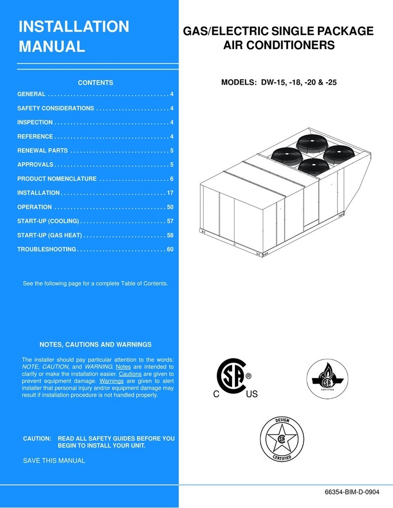
Unitary products group C*ED060A Series User manual
Other Unitary products group Air Conditioner manuals
Unitary products group
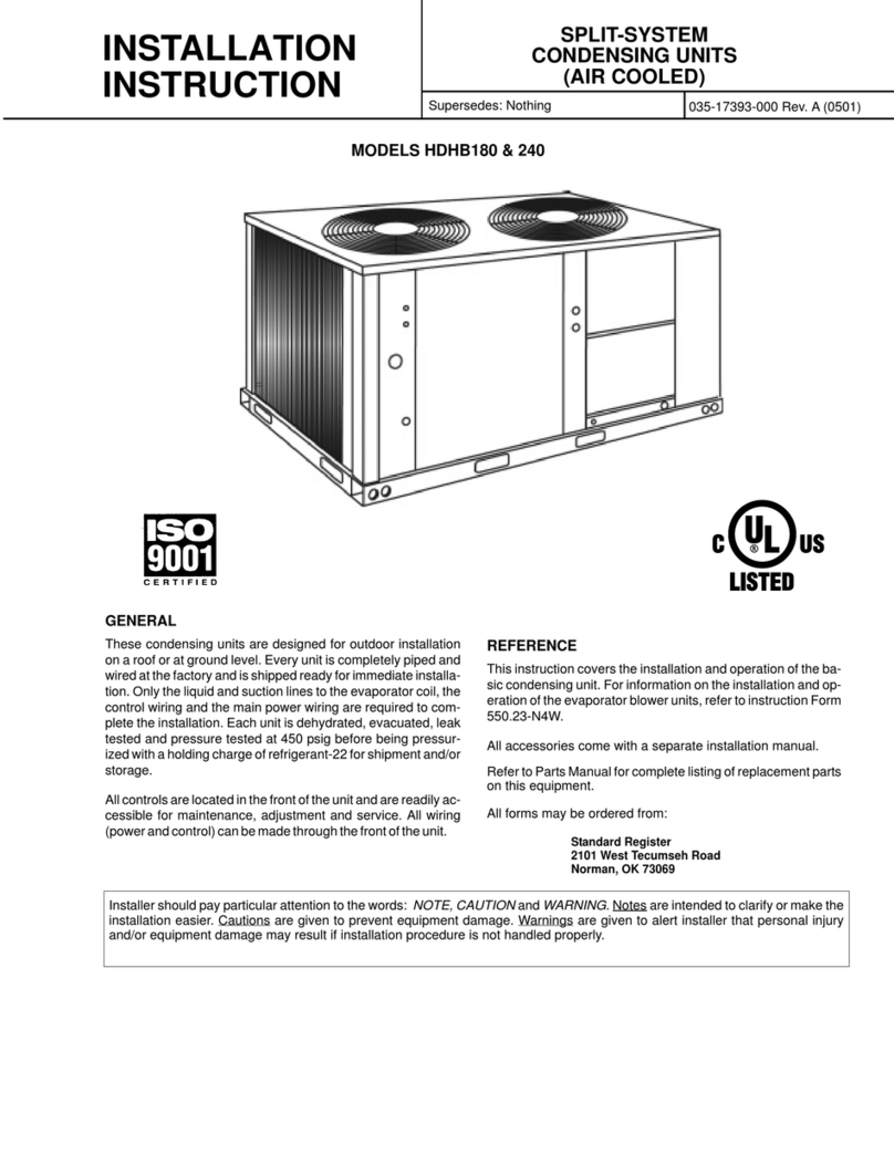
Unitary products group HDHB180 User manual

Unitary products group
Unitary products group YMB Series Guide
Unitary products group
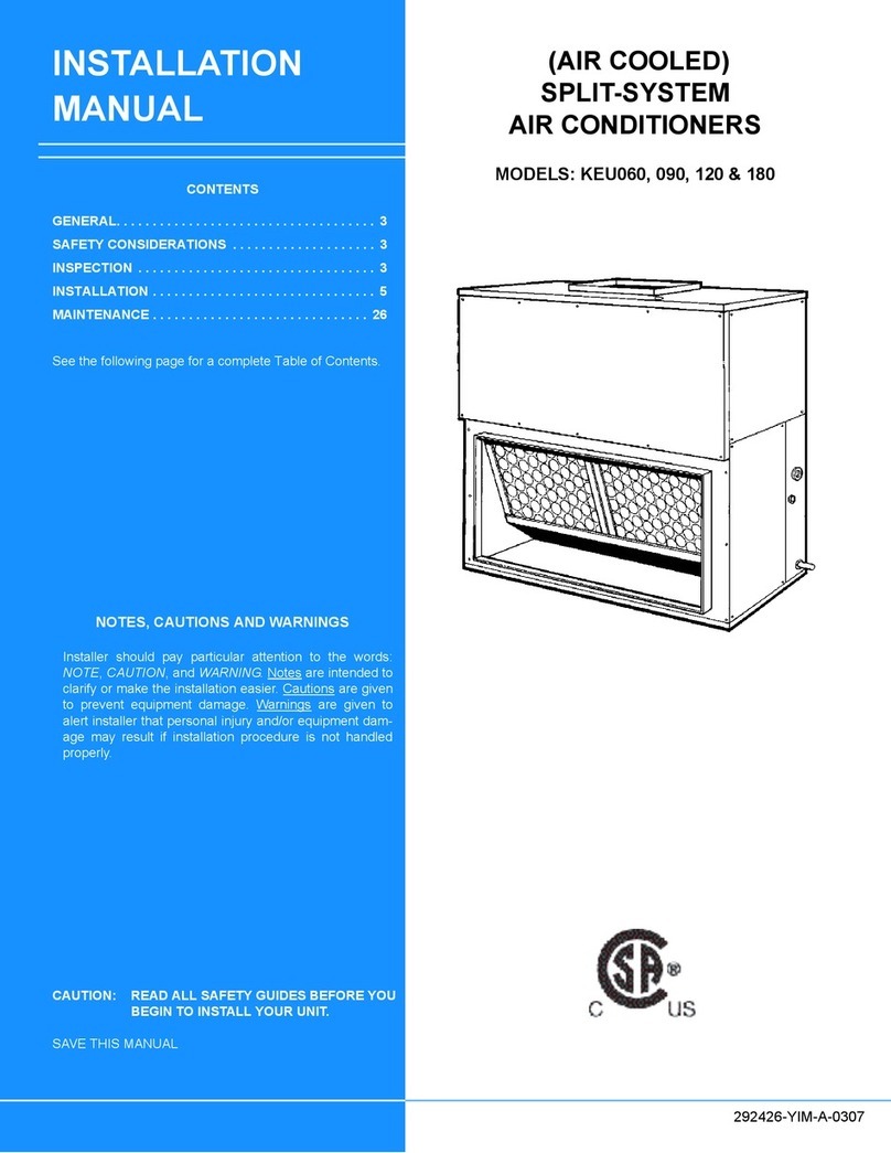
Unitary products group KEU060 User manual

Unitary products group
Unitary products group SUNLINE MAGNUM DJ180 User manual

Unitary products group
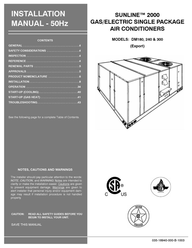
Unitary products group Sunline 2000 DM180 User manual
Unitary products group
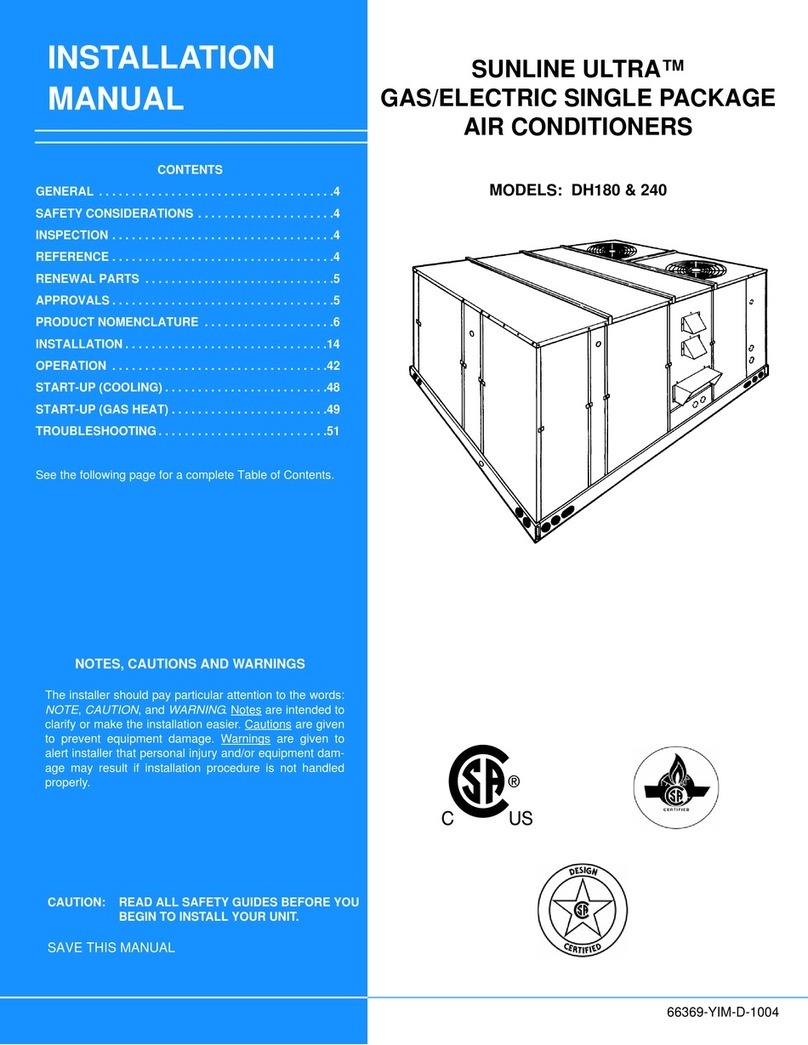
Unitary products group SUNLINE ULTRA DH180 User manual
Unitary products group
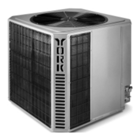
Unitary products group H4TS024 User manual
Unitary products group
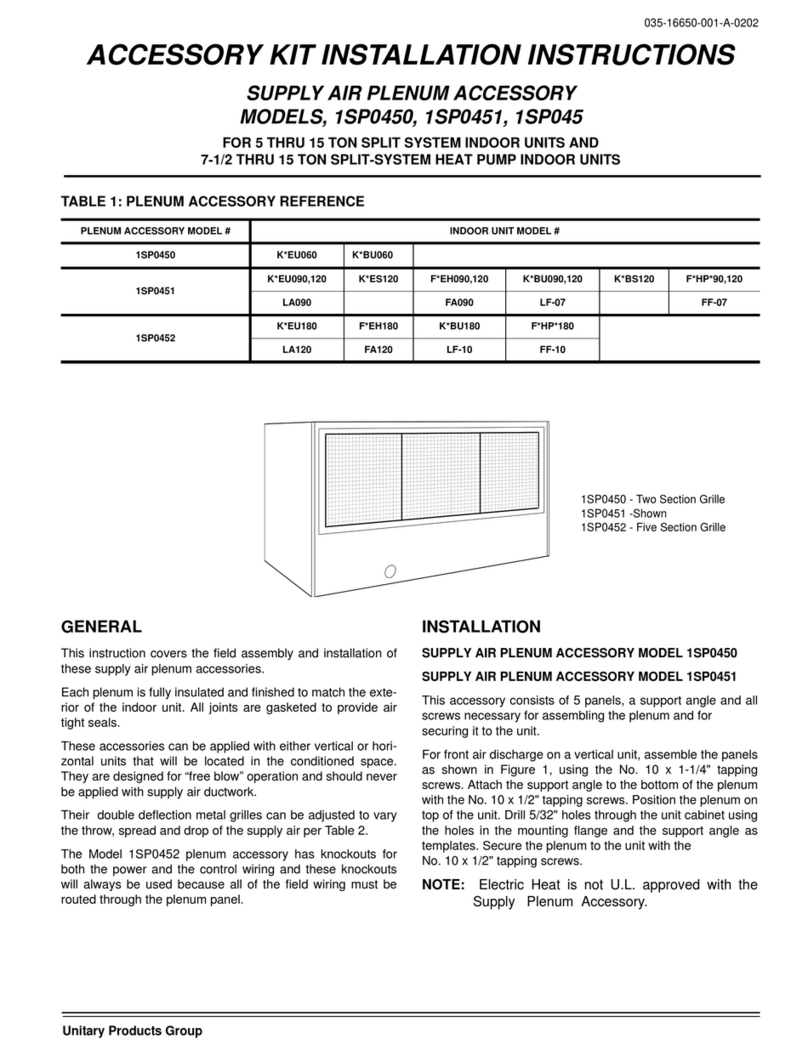
Unitary products group 1SP0452 User manual
Unitary products group
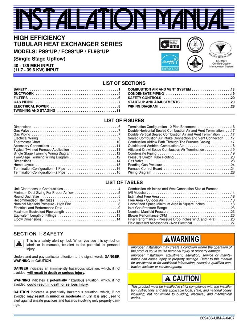
Unitary products group PS9*UP User manual
Unitary products group
Unitary products group CPH 060 Installation instructions
Unitary products group
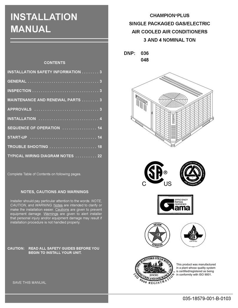
Unitary products group CHAMPION PLUS Series User manual
Unitary products group
Unitary products group DSH User manual
Unitary products group
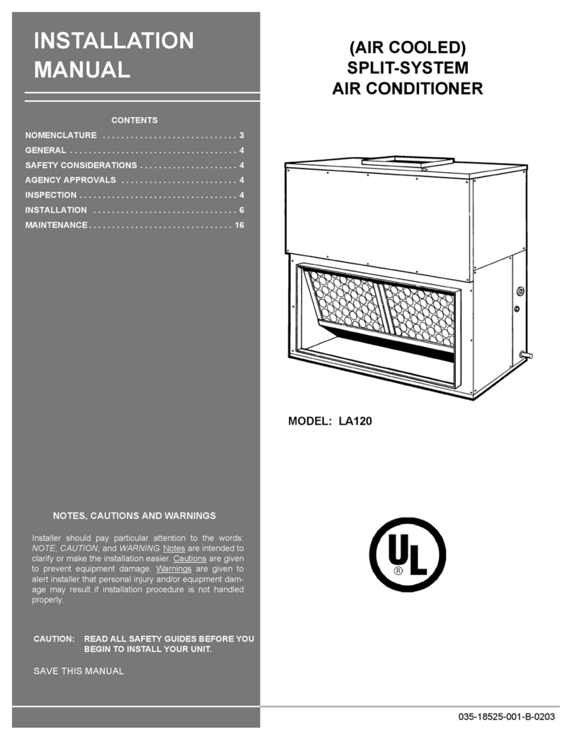
Unitary products group LA120 User manual

Unitary products group
Unitary products group DJ 060 User manual
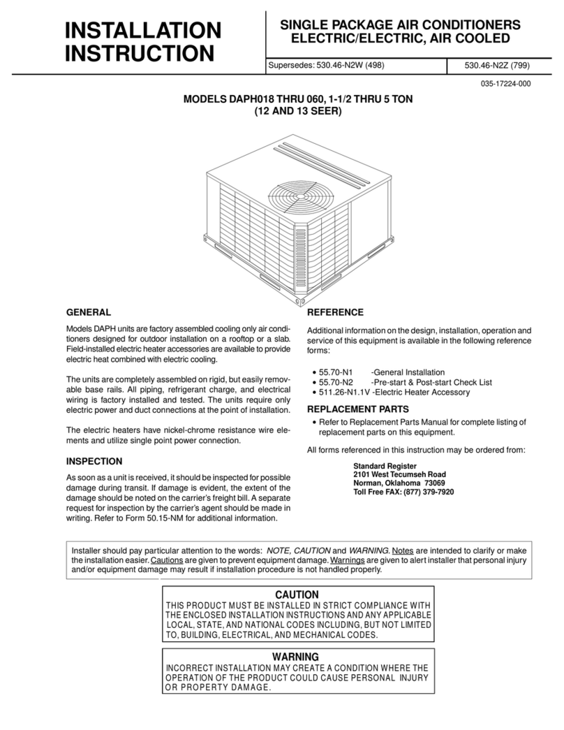
Unitary products group
Unitary products group DAPH Series User manual

Unitary products group
Unitary products group HA 300 User manual
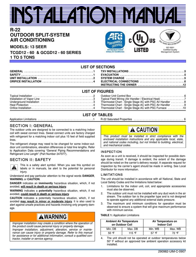
Unitary products group
Unitary products group 13 SEER TCGD12 - 60 SERIES User manual

Unitary products group
Unitary products group HA090 User manual
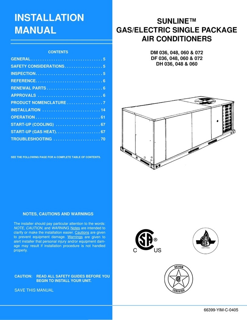
Unitary products group
Unitary products group DM 036 User manual
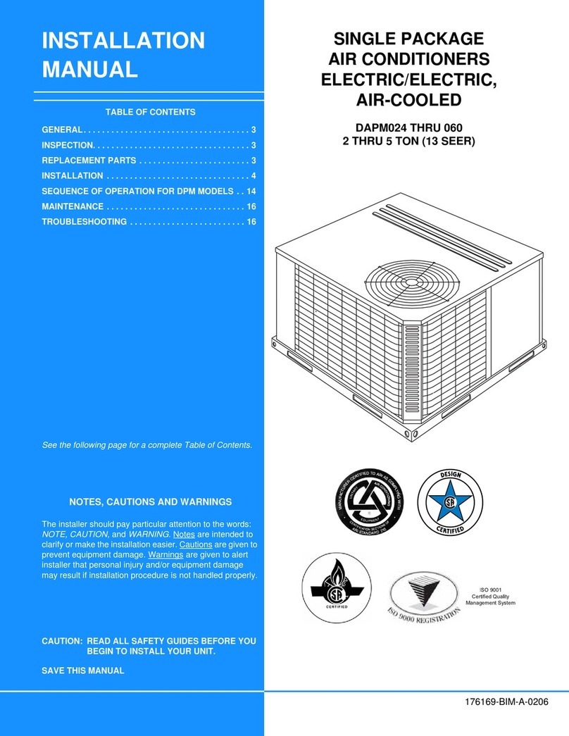
Unitary products group
Unitary products group DAPM024 User manual
Popular Air Conditioner manuals by other brands

Fujitsu
Fujitsu ASYG 09 LLCA installation manual

York
York HVHC 07-12DS Installation & owner's manual

Carrier
Carrier Fan Coil 42B Installation, operation and maintenance manual

intensity
intensity IDUFCI60KC-3 installation manual

Frigidaire
Frigidaire FAC064K7A2 Factory parts catalog

Sanyo
Sanyo KS2432 instruction manual

Mitsubishi Electric
Mitsubishi Electric PUHZ-RP50VHA4 Service manual

Panasonic
Panasonic CS-S18HKQ Service manual

Panasonic
Panasonic CS-E15NKE3 operating instructions

Gree
Gree GWH18TC-K3DNA1B/I Service manual

Friedrich
Friedrich ZoneAire Compact P08SA owner's manual

Daikin
Daikin R32 Split Series installation manual

