@
+91 7046223333 , 9427301436
www.utplindia.in
www
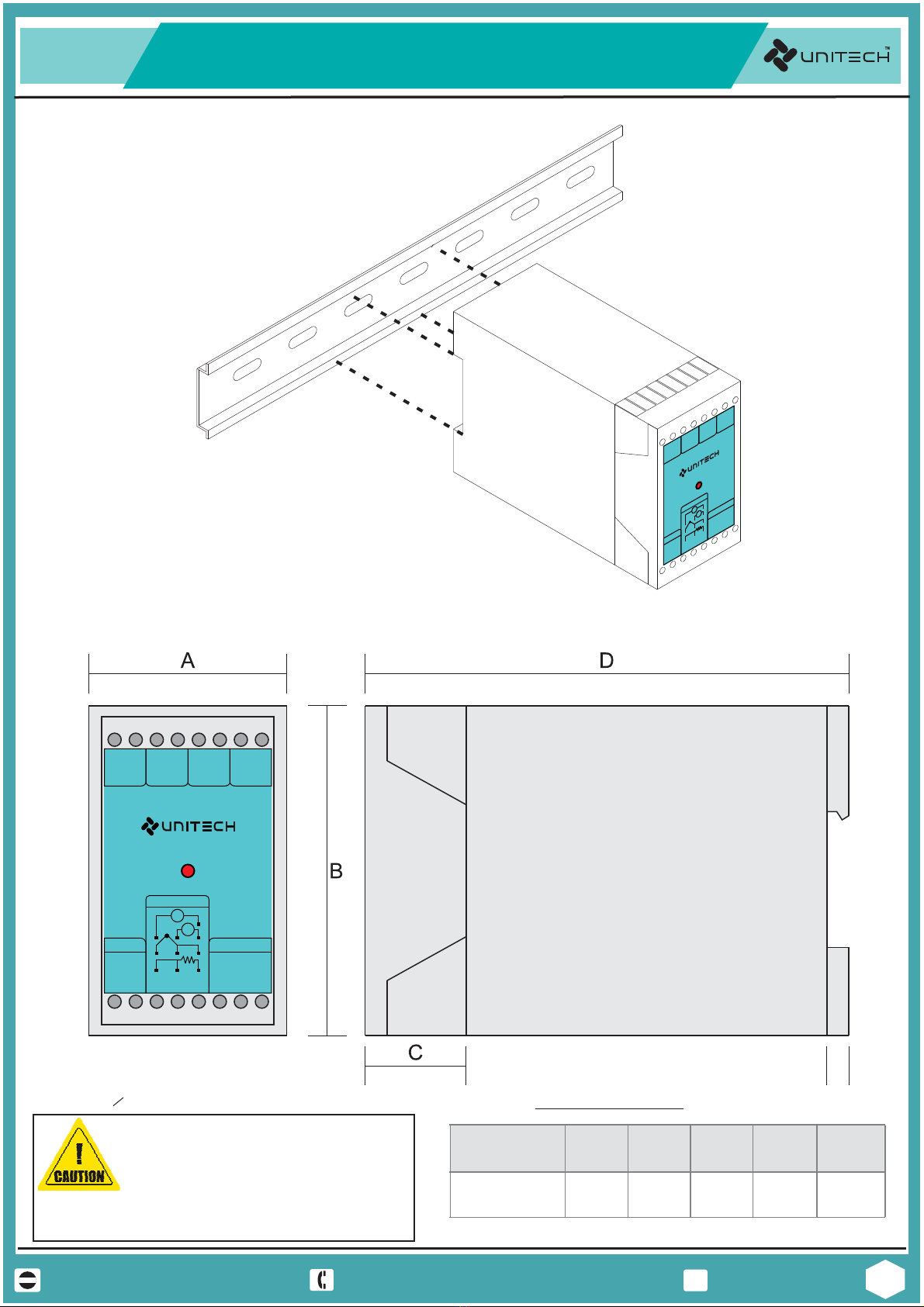
UT-1102
SIGNAL ISOLATOR
I
WARNING
Electrical Consideration / Precautions
The controller is considered “rack and panel mounted equipment” per EN 61010-1, Safety Requirements for
electrical equipment for Measurement, Control and Laboratory Use, Part 1: General Requirements. Conformity
with 2/23/EEC Low Voltage Directive, requires the user to provide adequate protection against a shock hazard.
The user shall install this controller in an enclosure that prevents OPERATOR access to the rear terminals.
FAILURE TO COMPLY WITH THESE INSTRUCTIONS COULD RESULT IN DEATH OR SERIOUS INJURY.
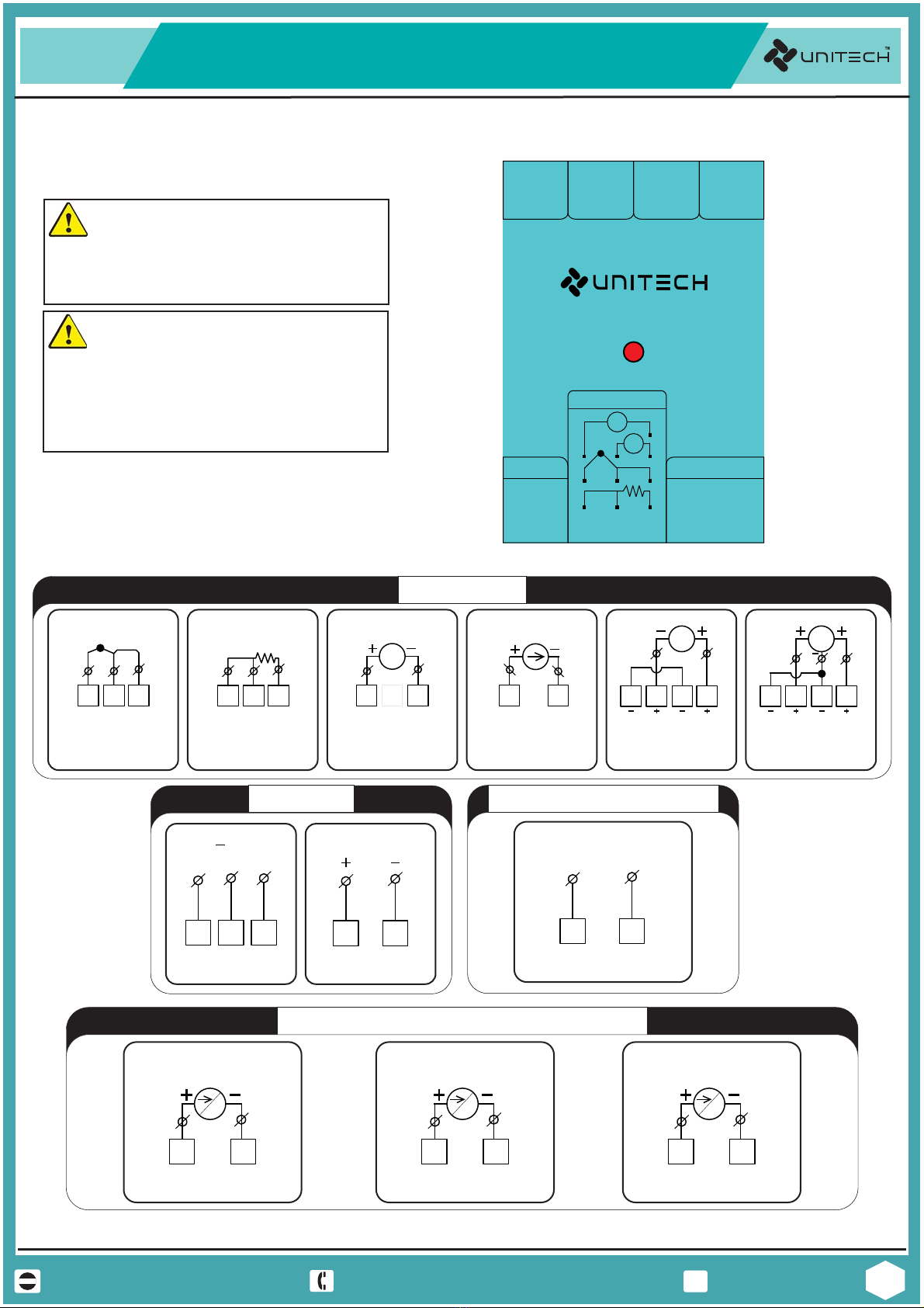
Shielded twisted pair cable is required for all Analog Input & Output, Process Variables,
RTD, Thermocouple, DC volts-mV, low level signal, mA, Alarm Outputs, and Computer
communication interface circuits.
CAUTION
FAILURE TO COMPLY WITH THESE INSTRUCTIONS MAY RESULT IN PRODUCT DAMAGE.
Power Supply / Wiring Requirements
Applying 240V AC to a controller rated for 12-24VDC will severely damage the controller
and is a fire and smoke hazard.
This controller is suitable for connection to 230 15% VAC, 50 Hz power mains.+
It is the user responsibility to provide the following
230 15% VAC - a switch, fuse (1/2A, 250V) or a circuit breaker.+
The above items should be installed together with UT-1412 for the products electrical protection.
The switch, Fuse or circuit-breaker should be located close to the controller, within easy reach
operator. The switch or Circuit-breaker should be marked as the disconnecting device for the
controller. applying power to Multiple instruments, make sure that sufficient current is supplied,
Otherwise, the instruments may not start up normally due to the voltage drop caused by the in-
rush current.
FAILURE TO COMPLY WITH THESE INSTRUCTIONS MAY RESULT IN PRODUCT DAMAGE.
Disposal action of Instruments follows as per country and regional law and rules & regulation also same in
international. Company might be follows as per rules.
DISPOSAL ACTION
PRE CAUTIONS, WARNING AND DISPOSAL ACTION
Line voltage Wiring