Uniteck UNIMPPT 80.15/24 User manual

EN
24/65 www.uniteck.fr
Dear customers, thank you very much for purchasing one of our Uniteck products. Please read carefully
and thoroughly all the instructions before using the product.
DESCRIPTION
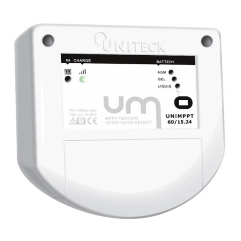
UNIMPPT is an advanced MPPT technology solar charge controller for autonomous photovoltaic system.
Through its integrated microprocessor, UNIMPPT provides an optimal charging current (voltage/current) for your
12 or 24V battery based on:
- battery technology (Gel/Liquid/AGM)
- the battery state of charge (advanced charging algorithm ALGOTECK)
- Voltage drops caused by battery wiring (remote sensor in option)
- ambient temperature which influences battery voltage (integrated temperature sensor or remote sensor in
option)
Thanks to its ALGOTECK load curve in 6 steps unique in the market, in addition to charge batteries at 100%,
UNIMPPT prevent them from all stratification phenomena, sulfation and improving their lifespan (Reconditioning
steps and Life+).
MPPT (Maximum Power Point Tracking) technology last generation, its MPPT algorithm optimized combined
with one of the fatest microprocessor on the market, researches in real time (refresh every 100 ms) the
maximum power point of solar panel, even under changing weather conditions (cloudy sky). Relative to a
standard regulator (PWM technology), UNIMPPT uses all the voltages of the at least one panels thereby enabling
to provide UP TO 40% more energy.
Moreover, UNIMPPT 80-15.24 incorporates a 12/24V controlled output avoiding deep discharges of your battery
and preserves their lifespan.
MPPT + ALGOTECK TECHNOLOGY
MPPT technology last generation combined with it’s at 6 steps new charging algorithm ALGOTECK in, UNIMPPT
has advantages below:
-Energy collection optimization relative to a PWM. UNIMPPT reconverts in charge intensity the unused
differential voltage from panel/battery with a standard regulator (PWM). This technology difference
results in 15% power gain of in the summer period and of 40% in winter sunny period when the voltage
it’s at its maximum (no decrease in voltage due to the increase in temperature of the panel).
-Energy collection optimization of during cloudy periods. Light intensity changes quickly and UNIMPPT
research in real time (refresh every 100 ms, among the fastest MPPT regulators on the market), the
point of power optimum of panel for more electricity production.
-Battery lifespan optimization. UNIMPPT constantly monitors the battery health status and charge status
to calculate and to deliver every day the best charge curve for the battery (voltage level, current level,
pulse rate, temperature ...)

EN
www.uniteck.fr 25/65
ADVANTAGE MPPT TECHNOLOGY VS PWM
MPPT FUNCTION EXPLANATION
Unlike a standard PWM regulator which lowers voltage panel at voltage battery based on the thresholds of
voltage define per his charge algorithm, a MPPT regulator (converter/regulator) uses all panels voltage and
reconvert the excess of voltage panel/battery in charge intensity (cf. patterns below)
PWM Regulator
Voltage = 18,7 V
Intensity = 5,43 A
generated power
100W
Voltage
Intensity
Vmp 12,5V
Imp 5,43 A
Output power
67W
MPPT Regulator
Voltage = 18,7 V
Intensity = 5,43 A
Power generated
100W
Voltage
Intensity
V 12,5V
I 7,6 A
Output Power
95 W*
* MPPT efficiency 95%
The MPPT gain unlike a PWM varies in function of:
- The battery state of charge
- The panel voltage
More battery is discharged and/or the panel voltage is high, more the MPPT regulator advantage over a PWM
regulator is important.

EN
26/65 www.uniteck.fr
ADVANTAGE TECHNOLOGY MPPT VS PWM (SUITE)
MPPT GAIN A MPPT OVER PWM
On a panel dedicated to battery charging (36 cells –voltage panel about 18V), an MPPT enables a gain in
production as a daily mean value 10-15% for summer until 30-40 % in winter.
Panel 100W in winter period (panel temperature 5 degrees)
Panel
voltage
(Vmp =
18,7V)
Voltage
drop due
to the
cables
(5%)
Voltage
battery
charge
Theorical
gain in
value
Theorical
gain in
%
Gain
rectified
MPPT**
Solar radiation
10H
20,2 V*
19,2 V
12,2 V
7 V
+ 57%
+ 53%
20,2 V*
19,8 V
12,5 V
7,3 V
+ 58%
+ 54%
20,2 V*
19,8 V
13 V
6,8 V
+ 52%
+ 48%
12H
19,2 V*
18,8 V
13,5 V
5,3 V
+ 39%
+ 36%
19,2 V*
18,8 V
14 V
4,8 V
+ 34%
+ 32%
16H
19,2 V*
18,8 V
14,6 V
4,2 V
+ 29%
+ 27%
Mean
40%
* Vmp at 25°C cell –rectified at 5°C with a temperature coefficient Vmp 0,34%/°C either 20,2V and with a
decrease of the battery voltage of 1V due to an increase in warmth of the panel when the full load (sun at
12H)
** MPPT efficiency 95%
Panel 100W in summer period (panel temperature 50 degrees)
Panel
voltage
(Vmp =
18,7V)
Voltage
drop due
to the
cables
(5%)
Voltage
battery
charge
Theorical
gain in
value
Theorical
gain in
%
Gain
rectified
MPPT**
Solar radiation
7H
17,11 V
16,3 V
12,2 V
4,1 V
+ 33%
+ 31%
17,11 V
16,3 V
12,5 V
3,8 V
+ 30%
+ 28%
17,11 V
16,3 V
13 V
3,3 V
+ 25%
+ 23%
12H
16,11 V
15,3 V
13,5 V
1,8 V
+ 13%
+ 12%
16,11 V
15,3 V
14 V
1,3 V
+ 9%
+ 12%
16H
16,11 V
15,3 V
14,6 V
0,7 V
+ 5%
+ 4%
Mean
+ 15%
* Vmp à 25°C cell -rectified à 55°C with temperature coefficient Vmp 0,34%/°C. until 17,11V and an increase
of the battery voltage of 1V due to an increase in warmth of heat from the photovoltaic panel when the full
load (sun at 12H)
** MPPT efficiency 95%

EN
www.uniteck.fr 27/65
ADVANTAGE TECHNOLOGY MPPT VS PWM (SUITE)
UNITECK MPPT ADVANTAGE
UNIMPPT research in real time (refresh every 100 ms, one of the fastest MPPT solar charge controller among on
the market), the optimum power point of panel, thus verifying if the voltage /intensity couple has changed to
modify its conversion parameters in input and thus to optimize the out power.
UNIMPPT thus ensures the power maximum even in changing weather conditions (cloudy sky).
V
A
1 2 3 4 5 6 7 8 9 10
25V
20V
15V
Maximum power point tracking
all the 100ms

EN
28/65 www.uniteck.fr
TECHNICAL ADVICE
Before connection, please consult the following points:
BATTERY
UNIMPPT has an automatic voltage detection. For its correct functioning, please check:
- the battery voltage is higher than 6V (required voltage for the startup of the solar charge controller)
- For 24V batteries, the voltage cannot be lower than 18V.
For flooded batteries, check the electrolyte level. If necessary, complete before charging.
For coupling, proceed as follows:
Some pieces of advice
In case of parallel
connection, favour
diagonal wiring for a
standardization of the
charge/discharge
Do not couple
batteries with
different capacities,
different age or
different technologies
Prefer a high-capacity
battery to 2 small
connected in parallel, for
equal capacity
PHOTOVOLTAIC PANEL
Check that the photovoltaic panel power or the panel photovoltaic park does not exceed 80V.
Refer to pages 10 and 22.
ELECTRICAL CONSUMERS
Before connecting your consumers to the solar charge controller and to prevent the solar charge controller
snapping into overload protection, check that the consumers do not exceed the Unimppt power rating
(Refer to the 12V/24V controlled output part for more details).
IN SERIES IN PARALLEL IN SERIES AND IN PARALLEL

EN
www.uniteck.fr 29/65
FRONT DEVICE - QUICK START
Solar energy (photovoltaic panel):
- Steady light, panel does supply current
- Blinking light, panel overvoltage
Command button/switch:
- On/Off 12V/24V controlled output:
push 1 second
- Battery selection: push 5 secondes -
then selection 1 sec.
Battery status:
- Blinking green: Full battery
- Green: charging
- Red: battery deeply discharged
Solar panel connection (12V or 24V)
External temperature sensor
Battery connection (12V ou 24V)
Battery selection:
- AGM: sealed lead-acid battery, maintenance-free,
VRLA.
- Gel : Gel cell battery
- Liquid: liquid electrolyte battery (with plug)
Solar panel connection
Controlled output light:
- On: light switches on
- Off : light off

EN
30/65 www.uniteck.fr
LATERAL FACES
Protection fuses against reverse battery polarity
Fuse 20A –Rapide Miniblade Type
Connexion Unisensor remote sensor.

EN
www.uniteck.fr 31/65
INSTALLATION - FIXING
UNIMPPT has been designed for an indoor use.
It incorporates an external temperature sensor which adjusts the load voltage according to the ambient
temperature for an optimal load (refer to the protection part for more details). Installing it near the battery
is recommanded. If it’s not possible, we recommended to use Unisensor remote sensor (page 11).
Fixing the solar charge controller can be made on a solid, stable and dry appropriate flat surface.
Standard wiring
Bulkhead adapter wiring
To provide the required air circulation for cooling the solar charge controller, let a 5-cm free space
(minimum) all around the product.
Break the 2 caps of the cover
with a pliers
Cables go out via the 2
orifices of the cover
Break the cap
Cables go through the
bulkhead
Close the cover by
pushing from the bottom to
the top
Close the cover by
pushing from the bottom to the
top
5cm
5cm
5cm
5cm

EN
32/65 www.uniteck.fr
COMPATIBILITY PANEL
UNIMPPT is Buck Synchrone technology. It converts panel voltage in more lower value voltage for the battery.
Generator powered on happens is if the PV voltage (Voc) exceeds the battery voltage more than +5V.
The charger will turn off when voltage PV (Voc) will be less than Vbat +1V.
Check before connection
Maximum PV voltage in open circuit of the at least one panel in series (Voc) do not excess
80V.
A superior voltage can damage the regulator.
This damage is not covered by the warranty.
His charge intensity is 15 A with 12V and 24V. Upon exceeding in input, UNIMPPT will limit, without damage
for the regulator, its input power at this value.
Panel power
The production solar panel values are given according to conditions test normalized (STC): 1000W/m² solar
radiation, cell temperature at 25°C.
In basic using, normal operating cell temperature is 45°C +/- 2% (Normal Operating Cell Temperature: NOCT)
and solar radiation is 800W/m². A 300W panel produce as show the table below in reality 200W. UNIMPPT
80.15/24 which can be converted in input until 200W in 12V and 400W in 24V, is perfectly suited for panel
power up to 300W* with a 12V battery or 600W* with a 24V battery.
*Voltage Uocv of the at least one panel = 80V max.
UNIMPPT 80.15/24 uses all panel power up to 300W peak.
Panel power
(norme STC)
Real power rectified with
temperature
(8% decrease)*
Real power rectified at 800W
solar radiation
(25% decrease)**
Power with increase
wiring
(2 to 5 %)
250W
230W
170W
165W
260W
240W
180W
175W
270W
250W
170W
180W
280W
255W
190W
190W
290W
265W
200W
195W
300W
275W
205W
200W
*Rectification temperature = 0,4%/ degree above 25°C either 8% increase for 45°C (NOCT)
*** Sunny rectification = CF explanation below
Panel power delivered at real solar radiation maximum compared to solar radiation theoretical STC
!
!
8 A
10V
6 A
15V
20V
25V
7 A
5 A
4 A
3 A
2 A
1 A
1000W/m² (normative)
800W/m²
500W/m²
250W/m²
25 % power in less
between normative sunny and
maximum sunny in France
Lille 300W/m² 700W/m²
Marseille 500W/m² 800W/m²
Winter Summer
Solar radiation in France

EN
www.uniteck.fr 33/65
COMPATIBILITY PANEL (SUITE)
Panel compatibility overview
With 12V battery
With 24V battery
1 panel
5W ►300W
5W ►300W
Panel 24V
(72 cells)
+
2 panels
5W ►150W
(x2)
Series or parallel*
5W ►300W
(x2)
Series
+ +
3 panels
5W ►100W
(x3)
Series or parallel*
5W ►200W
(x3)
Series
+ + +
4 panels
Not compatible
5W ►150W
(x4)
Series or parallel
Series or parallel* connexion
In case of multi-panel configuration, prefer parallel connexion which ensures an optimum production
especially in shading situation.
Series Parallel
In case of parallel coupling, the power panel adds up.
In case series coupling, the total power equals to the lowest power panel.
Advantages / Disadvantages
Series
Parallel
Advantages
Connection simplified
No power decrease when panel is
shaded.
Disadvantages
Power decrease if a panel is shaded (tree,
building, chimney, sail, ... )
Cf schema above
Use derivation connectors and
cable section more important
Cf schema above
1A + 5A
= 6A
1A + 5A
= 1A

EN
34/65 www.uniteck.fr
CONNECTION
For solar regulator connection, we advise you to be surrounded by qualified person in accordance with
standards in force in your country.
Connect each component to symbols established for this purpose (cables not included).
Please follow the connection order in accordance with the polarities.
In case of non-compliance, your solar charge controller as well as your battery may be damaged.
Connect your battery to the solar charge controller (+ and -)
Battery indicator lights on
Connect your solar panel to the charge regulator (+ and -)
Refer to pages 6 and 20.
Select your battery technology:
- Press and hold the switch for 5 seconds, the active light flinkers
- Select your battery technology by pressing the switch
Liquid: Open lead/acid liquid battery
Gel: Gel battery
AGM: Lead battery (maintenance-free), AGM…
- To confirm your selection, wait for 5 secondes. The light becomes
fixed again. Unimppt memorises your last setup.
Connect your consumer to the solar charge controller (+ and -)
In case of disconnection, follow the opposite order

EN
www.uniteck.fr 35/65
12 OR 24 V DC CONTROLLED OUTPUT
The controlled output is controlled by an electronic switch that can switch off or switch on the consumers
of your installation. You can connect DC consumers:
12V or 24V, depending on the battery that is connected, such as a light, a pump, a motor…
The maximum continuous power accepted is is 15A (either 200W in 12V or 400W en 24V).
For starting up, some consumers have a current inrush that can be higher than the indicated rating power.
UNIMPPT allows those temporary overconsumptions, subject to a limit of 40A during 1s.
Nevertheless, you can directly connect the consumers to the battery without going through the connection
of the Unimppt, thus use more the battery. However, the overload protections and more importantly the
battery undervoltage will not be ensured. You will have to ensure, by yourself, the surveillance of the
installation thanks to battery status lights and to cut off the consumers if necessary.
GROUNDING –INSTALLATION CLASS
The grounding of solar charge controller is not regularly necessary. If you want anyway achieve a grounding,
always do on the negative pole of the battery.
If the no-load voltage of your solar panels is higher than 75 V (throughout the temperature range of using),
the whole solar system must be installed according to the class of protection II.

EN
36/65 www.uniteck.fr
VOLTAGE AND TEMPERATURE REMOTE SENSOR (OPTION)
ADVANTAGES
The intern battery voltage varies according to ambient temperature. (30mV per degree).
To deliver the best voltage and avoid overloading or under loading of the battery UNIMPPT is originally
equipped with a temperature sensor integrated on regulator gear. With this, UNIMPPT measures the ambient
temperature to adjust charging voltage according to battery manufacturer’s recommendations. (30mV in 12V
and 60mV in 24V per °C under and over the reference temperature at 25°C).
However, when there is a temperature difference
between the regulator environment and the battery (ex.
regulator located in a technical room and battery stocked
in a block), it is recommended to use Unisensor remote
sensor. In this case, UNIMPPT will use as the temperature
reference, no the ambient temperature measured by the
regulator but the temperature measured by the remote
sensor.
UNISENSOR allows too to optimize voltage
measurement for more charge precision. Thanks,
Unisensor, the voltage measurement doesn’t do
that anymore at across the regulator, but directly
on the battery to avoid voltage drops cause by
wiring. In order to measure and control the charge
more precisely.
INSTALLATION AND CONNECTION
•Fix the sensor thanks 2 bolts or double-sided
sticker to the nearest of the battery.
Warning: Do not theard it in the battery
•Connect 2 measure wires on Unisensor.
and
•Ensure that green light is correctly turned
on. If the yellow light is turned on, a polarity
reversal occare. Modify wiring until flash
green turn on.
•Connect cable between the regulator and the
sensor. and
Red wire
Red
cable
Black
cable
Black wire

EN
www.uniteck.fr 37/65
FUNCTIONNING –CONTROL PANEL
PHOTOVOLTAIC PANEL DISPLAY
Steady green :
Photovoltaic panel supplies
electricity
Blinking green :
Batterty in overvoltage
BATTERY CHARGE DISPLAY
Steady green :
Charging
Blinking green :
Battery charged
Steady orange:
Battery discharged
Advice: If you do not use the
controlled output, reduce or
switch off your consumers.
Steady red :
Battery deeply discharged
Advice: If you do not use the
controlled output, imperatively
switch off your consumers until
the light becomes green again.
12V/24V CONTROLLED OUTPUT DISPLAY (ACCORDING TO THE BATTERY)
Red light on:
Active output
Blinking read :
Overconsumption or short
circuit
Off :
Inactive output
Green +Flash
Green
Green + Flash
Green
Orange
Red
Red
Red + Flash

EN
38/65 www.uniteck.fr
ALGOTECK CHARGING CURVE
BATTERY CHARGE STEPS
Its charge algorithm ALGOTECK, unique on the market, is composed of 6 steps.
1
TEST
UNIMPPT determines on a daily basis health status and
charge status of your battery and attach steps and charge
levels required for the maintenance of your battery.
2
BOOST CHARGE
(I)
UNIMPPT uses 100% of energy from solar panel, until this
voltage reaches the equalization voltage. The battery is
charged at 80%.
3
EQUALISATION
(max. 4 heures)
UNIMPPT equates the charge on all battery elements
(battery charged at 100%)
4
RECOND.
Only in liquid mode, this step can stir, thanks a pulsed
current, the electrolyte of your battery for to avoid all
stratification or sulfation phenomena.
5
100%
The battery charge is over. The green flash "loads"
blinking. UNIMPPT continues to deliver the current lowest
for to compensate the battery self discharge.
6
LIFE+/STORAGE
UNIMPPT compensates the natural battery self discharge,
with a pulse charge for more battery lifespan.
Voltage threshold
Gel
AGM
Liquid
Boost
Absorption
14,2 V
-
14,4 V
14,4V
14,5 V
14,5V
Equalization
-
-
14,8V
Floating
13,9V
13,9V
13,9V
Nb: the voltage levels above are ajusted per ALGOTECK conditions

EN
www.uniteck.fr 39/65
ALGOTECK CHARGING CURVE (NEXT)
CHARGE CURVE REGULATION DEPENDING ON THE BATTERY TECHNOLOGY
To perfectly recharge all lead acid batteries, Unimppt adapts its load curve according to the " battery technology"
previously selected:
"Liquid" Batteries Mode:
Liquid electrolyte batteries require higher loads to avoid any stratification of the electrolyte. Stratification is a
non-homogenous blend of the electrolyte. Acid is concentrated at the bottom and the water at the top (due to
its lower density). This phenomenon leads to freezing risks or oxidation of the plates. To avoid this, Unimppt
makes (in liquid batteries mode) an equalisation charge that mixes the electrolyte, which is essential to preserve
the lifespan of your battery.
"AGM" Batteries Mode/ "GEL" Batteries Mode :
Waterproof batteries (AGM or GEL) require a precise control of the charge voltage to avoid bleeding
phenomenons. Bleeding is an electrochemical reaction that leads to the release of oxygen and hydrogen gases
inside the battery when the battery voltage reaches a point named "gasification voltage".
This voltage changes according to the type of the batteries (AGM or GEL). Depending on the selected mode,
Unimppt releases a voltage level adapted to the technology of your battery for a recharge up to 100%.
Regulation by external temperature
Chimical characteristics of the battery vary depending on the ambient temperature.
With its external temperature sensor, Unimppt adapts precisely its charge voltage in relation with the reference
temperature of 25°C, of +/- 30mV (+/-60mV - 24V by °C), which avoids overloads and under loads.

EN
40/65 www.uniteck.fr
INTEGRATED PROTECTIONS
For a safe use, Unimppt has several protections that preserve the solar charge controller, the battery and the
consumers in output:
-Panel polarity reversal protection,
- Protection against panel short-circuits,
- Protection against reversed current: prevents reversed current towards the solar
panel during the night.
- Battery polarity reversal protection,
- Protection against battery overconsumptions (controlled output),
- Battery overvoltage or under voltage protection (controlled output),
- Protection against deep discharges (controlled output).
- Consumers polarity reversal protection (protects the solar charge controller, not
the consumer),
- Protection against short circuits in output.
- Thermal protection.

EN
www.uniteck.fr 41/65
TROUBLESHOOTING, CAUSES, REMEDIES
Error message
Causes
Solution
No light switch on
The solar charge controller
needs the battery voltage to
be higher than 6V to be able
to start when connecting the
battery
Check the battery voltage,
recharge it if necessary.
Battery polarity reversal
Check fuse battery
Battery connection problem
(cables, terminals...)
Check connections
Defective battery
Replace your battery,
following the disconnection
and connection order (refer
to the installation and
connection part)
Panel light off while sun
is present
Solar panel disconnected, not
properly connected, or short
circuit
Check connections (polarity
and connection)
Normal functionning: The
panel voltage is lower than
the battery voltage or too low
sunshine.
The panel gets its charge
back as soon as the panel
voltage is higher than the
battery voltage.
One or several cells of your
panel are hidden.
Check the cleanliness of your
solar panel and make sure
none of the cells are hidden.
Green +
Flash
Blinking panel light
(green)
Battery overvoltage or
undervoltage
Disconnect the solar panel,
then make sure the battery is
not in a overvoltage state or
that the voltage of your
battery coupling does not
exceed the voltage accepted
by the solar charge controller
(12V/24V)
Orange
Voyant charge orange
Battery discharged
Usual charge, light goes
green as soon as the battery
is charged.

EN
42/65 www.uniteck.fr
TROUBLESHOOTING, CAUSES, REMEDIES (NEXT)
Error message
Causes
Solution
Red
Red charge light.
Consumers are cut
(12/24V light off).
Battery deeply discharged.
Usual behaviour,
Light goes green as soon as
the battery is charged.
Red + Flash
12V output light :
Blinking red
Solar charge
controller in a
protection state,
cut the 12V/24V
output.
Over-consumption.
The total consumption of
consumers exceeds the rating
power of the solar charge
controller.
Reduce consumers. Refer to
“The controlled output part”.
Then restart the output. The
consumers will be powered
within 3 seconds.
Short circuit output
Check connections.
In the case of first short-
circuit, the solar charge
controller will automatically
recharge consumers within
10 seconds.
In case of second short-
circuit, you need to restart
the 12V output, by pressing
the button. The consumers
will be recharged within 3
seconds.
Red + Flash
Battery lights :
Blinking
simultaneously
Thermal protection: internal
solar charge controller
temperature exceeds 60°C.
Solar charge controller in a
protection state. Charge and
consumers are cut
Wait the end of the cooling-
off period (<55°C)
Control the source of the
overheating (mounting
location, other heat sources).
Provide an adequate
ventilation to the solar
charge controller
As soon as the solar charge
controller gets back to its
normal functionning
temperature, it will restart
automatically.

EN
www.uniteck.fr 43/65
WARNINGS AND PIECES OF ADVICE
•UNIMPPT is designed to be exclusively used with photovoltaic systems and lead acid batteries with
liquid electrolyte, gel cell (Gel), sealed AGM types.
•Do not attent under any circumstances to charge other batteries than acid-lead batteries (non-
rechargeable batteries for example).
•Use UNIMPPT in a well-ventilated area, sheltered from rain, humidity, dust and condensation.
•Follow manufacturer’s instructions and safety procedures of the battery. In case of doubt, consult
your retailer or installer.
•Batteries can produce flammable gas. Avoid flames, sparks.
•During battery maintenance (except GEL), there is a risk of acid leaks so protect yourself.
•Never short circuit + and - of the battery or cables: risk of explosion or fire.
•Maintenance: check the wiring and all connections at least once a year.
•All tasks must be realised in compliance with the country regulations in force regarding electricity.
•The device used in your installation such connectors, cables, fuse, disconnectors, … must be adapted
and in conformity with law and regulations in force in the country for application regarded.
•This device is not designed to be used by people (including children) whose physical, sensory or
mental abilities are reduced, nor by people lacking of experience or knowledge unless they have
benefited of supervision or prior instructions concerning the use of the device given by a person
responsible for their safety.
•IPlease keep an eye on children to ensure that they do not play with the device.
PICTOGRAMS
Device conform to applicable
European Union directives
For indoor use, do not expose to the rain
Caution! Before using, read the
instruction manual utilisation
Caution explosive gases, avoid sparking and
naked flames.
Product under selective
collection- Do not throw it in a
household waste.
Choose a sheltered local with adequate
ventilation or especially equipped.
IP32
Protected against foreign bodies larger than 2,5 mm and against rain striking at angles up to
15° from vertical
Table of contents
Other Uniteck Controllers manuals
Popular Controllers manuals by other brands

Allen-Bradley
Allen-Bradley MicroLogix 1400 user manual

Digital Equipment
Digital Equipment DEC LANcontroller 601 Problem Solving

Morningstar
Morningstar SUNSAVER MPPT Series Installation and operation manual

ACME
ACME VD-T XLR user manual

DH Instruments
DH Instruments MPC1-1000 user manual

Banner
Banner XS26-2 Series manual