MERRICK MC3 User manual

MC³ Controller
Hardware Manual
Revision 2
MERRICK INDUSTRIES, INC.
10 Arthur Drive
Lynn Haven, FL 32444 U.S.A
Tel:+1 850.265.3611
Fax+1 850.265.9768
www.merrick-inc.com

Revisions
0 06/08/04 RGB Initial Release
1 06/30/04 RGB
2 01/05/05 RGB
All trademarks referenced are the property of their respective owners.
PROPRIETARY NOTE
The information in this manual, including technical data and copies of drawings, embodies information proprietary to Merrick
Industries, Incorporated. This manual is provided to the user of equipment purchased from Merrick Industries, Inc. for use only in
operation or maintenance of such equipment. Such information in this manual is not to be used, disclosed, copied, or reproduced in
whole or part for any use other than that indicated above, or for any other purpose detrimental to the interests of Merrick Industries,
Inc. Patents owned by Merrick Industries, Inc. have been issued or are pending on at least some of the information in this manual,
and unauthorized use of this subject matter of such patents is a violation of such patents and is prohibited

Table of Contents
Introduction ...................................................................................................................................... 4
Controller Enclosures ...................................................................................................................... 5
Panel Mount................................................................................................................................. 5
Wall Mount ................................................................................................................................... 5
Door Mount .................................................................................................................................. 6
Installation........................................................................................................................................ 7
Physical Installation ..................................................................................................................... 7
Panel Mount ............................................................................................................................. 7
Wall Mount................................................................................................................................7
Door Mount............................................................................................................................... 7
Card Stack Assembly ...................................................................................................................... 8
Connections ................................................................................................................................. 8
Card Stack with Revision 11 or newer CPU Board .............................................................. 9
Card Stack with Revision 10 or older CPU Board .............................................................. 10
Controller Disassembly .............................................................................................................. 11
Controller Reassembly............................................................................................................... 11
CPU Board..................................................................................................................................... 12
New CPU Board (Rev 11 or Newer) .......................................................................................... 12
Communication Ports ............................................................................................................. 12
COM 1 RS-232 J7 .............................................................................................................. 12
COM 1 RS-485 4 WIRE J6................................................................................................. 12
COM 2 RS-232 J4 .............................................................................................................. 13
COM 2 RS-485 4 WIRE J5................................................................................................. 13
Board Features .......................................................................................................................... 13
Option Switch Settings ........................................................................................................... 14
LED Display............................................................................................................................ 14
JTAG/Service Port (J8) .......................................................................................................... 14
Old CPU Board (REV 10 or older) ............................................................................................. 15
Communication ports ............................................................................................................. 15
Comm 2 (RS-232)............................................................................................................... 15
Board Features....................................................................................................................... 16
Jumper Settings.................................................................................................................. 16
Printer Operation (Old CPU Only) ...................................................................................... 16
HPAD Board .................................................................................................................................. 18
Straps......................................................................................................................................... 18
HPAD 1/2 Determination............................................................................................................ 18
PCIO Board ................................................................................................................................... 20
PCIO 1/2 Determination............................................................................................................. 20
Connections ............................................................................................................................... 21
Analog I/O Current/Voltage Strapping ....................................................................................... 21
Analog Input............................................................................................................................... 21
AIN Adjustments..................................................................................................................... 22
Analog Outputs .......................................................................................................................... 22
MC3 Hardware Manual i

AOUT Adjustments................................................................................................................. 22
Adding an additional PCIO board to a MC3controller ............................................................... 22
LTI Board ....................................................................................................................................... 23
Connections ............................................................................................................................... 23
Serial Communications (for Older CPU Boards).................................................................... 23
Encoder .................................................................................................................................. 24
EMT ........................................................................................................................................ 24
Backplane Boards ......................................................................................................................... 25
DC Style Backplane Board - BKPN ........................................................................................... 26
AC Style Backplane Board - BPAC ........................................................................................... 27
Power Supply Assemblies............................................................................................................. 28
MC3DC Power Cables............................................................................................................... 28
MC3DC Power Cable Details .................................................................................................... 30
Power Receptacle and Switch............................................................................................ 30
Display Assembly .......................................................................................................................... 32
LCD Board ................................................................................................................................. 32
Brightness and Contrast Adjustments.................................................................................... 32
LCD Display ............................................................................................................................... 33
Replacing Backlight Assembly ............................................................................................... 33
Touch Keypad ........................................................................................................................ 33
Touch Screen Location Codes................................................................................................... 34
MC3Troubleshooting ..................................................................................................................... 35
MC³ Crash screens .................................................................................................................... 35
Start-Up Crash ....................................................................................................................... 35
Parameter Corruption ......................................................................................................... 35
Controller Firmware Upgrade ............................................................................................. 35
Fatal Error Crash.................................................................................................................... 36
Forcing a Parameter Reset ................................................................................................ 37
Controller Reboots and Displays Ram Reset Screen ........................................................ 37
Unit does not power up –........................................................................................................... 37
LCD too dark/light or out – ......................................................................................................... 38
No Belt Load or Weight.............................................................................................................. 38
No Speed Detected.................................................................................................................... 39
Analog Output Problem.............................................................................................................. 39
Analog Inputs ............................................................................................................................. 39
MC3 Flashloader Programming (appLication upgrade) ................................................................ 41
Procedure for Rev 10 or earlier CPU boards............................................................................. 42
Procedure for Rev 11 or Later CPU boards............................................................................... 43
Sample Session ......................................................................................................................... 44
STORAGE ..................................................................................................................................... 45
STORAGE ON RECEIPT FROM FACTORY ............................................................................ 45
Storage Longer than 6 Months............................................................................................... 45
Storage up to 6 Months .......................................................................................................... 45
MC3 Hardware Manual ii
Storage Following Use............................................................................................................... 45
Operation After Storage ............................................................................................................. 45
SPARE PART LIST ....................................................................................................................... 46
MC³ Controller Spare Parts List................................................................................................. 46
MC³ Panel Mount A30685...................................................................................................... 46
MC³ Wall Mount A30833, A31534, A37244 ........................................................................... 46
MC³ Door Mount A33432 (Hitachi)......................................................................................... 47
MC³ Door Mount A39307 (Hantronix) .................................................................................... 47
Accessories................................................................................................................................47
I/O System.............................................................................................................................. 47
Options (Communication)....................................................................................................... 48
Spare I/O Plugs and Miscellaneous ....................................................................................... 48
Feeder Connection Board (FCB)............................................................................................ 48
APPENDIX A ................................................................................................................................. 49
Panel Mount (A30685) – Dimensions ........................................................................................ 49
Wall Mount (A30833, A31534) – Mounting Dimensions............................................................ 51
Wall Mount – Mounting Dimensions cont .................................................................................. 52
Door Mount (A33432, A39307) - Dimensions............................................................................ 53
Door Mount Power Supply Mounting Dimensions (S60213, 19-102-32402)............................. 54
Door Mount Power Supply (VL30) Mounting Dimensions (A36539) ......................................... 54
Backplane Mounting Dimensions (M21882, M22108, M22535)................................................ 55
Watchdog Timer Board Mounting Dimensions (N41215) .......................................................... 55
IOC Input Connection Board (M22536) ..................................................................................... 56
MC3 Hardware Manual iii

INTRODUCTION
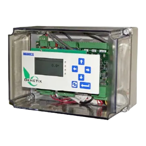
Merrick MC³ controllers are used in industrial weighing applications, typically handling a material
feeder, conveyor belt scale or flow meter. This manual describes the MC³ hardware. It is a
microprocessor based system, with support for:
•Isolated Analog I/O, 4..20 ma or 0..10V,
•Digital I/O, dry contacts or 110V AC,
•Special Isolated Load Cell inputs,
•Special inputs for Quadrature Encoders,
•Special outputs for External Totalizers.
The MC³ hardware is a platform for different Firmware Applications, which can be changed and
upgraded in the field.
The major components in the MC³ are
•Mechanical enclosure. There are three different versions, Panel, Wall and Door mount.
•Card Stack. Printed circuits boards in a standard PC/104 configuration.
•Graphical Display and Touch Screen.
•Power Supply, providing +5, +12 and -12V DC to components, inputs and outputs.
•I/O racks for digital I/O
The controller is scalable and configurable by means of cards in the card stack and I/O racks.
MC3 Hardware Manual 4

CONTROLLER ENCLOSURES
PANEL MOUNT
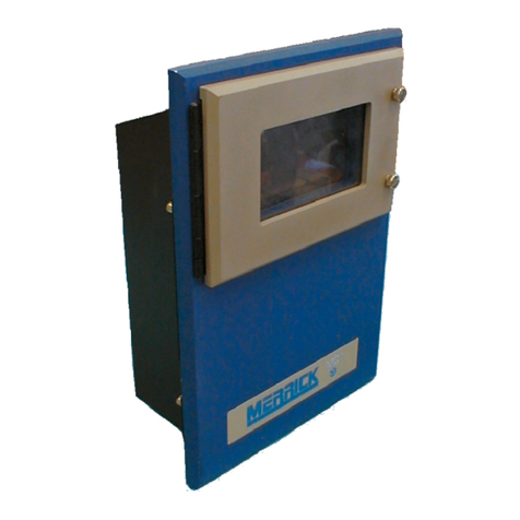
The Merrick MC³ Panel Mount Controller is
designed for mounting in a control cabinet.
It is suitable for use in environments that
are generally clean, and within the
temperature range of 32oto 104oF (0oto
40oC). It must be protected from water or
significant dirt or dust. See the drawings
provided in Appendix A (page 49) for exact
specifications on the controller enclosure.
The panel mount enclosure consists of a
rectangular box with a hinged door on the
rear covering the I/O connections, a
removable top cover, a system-grounding
bar and a sliding tray. The slide tray allows
the Card Stack Assembly to be slid out of
the back of the enclosure for easier
maintenance while the controller is mounted into a panel. The Display assembly is mounted on
the front bezel. The top cover may be removed for easier access to the boards. Access to the
terminal blocks for interconnection with other equipment is obtained by unscrewing the rear
cover.
WALL MOUNT
The Merrick MC³ Wall Mount Controller
is designed to be weatherproof, and can
be mounted most anywhere. The
temperature range of this controller is
within 14oto 122oF (-10oto 50oC).
Merrick recommends that the controller
should be located out of direct sunlight
and away from dripping water and must
be protected from heavy rain. Refer to
the drawing in Appendix A on page 51
for detailed specifications of the
controller enclosure.
The wall mount enclosure is available in
NEMA-4, NEMA-4X or NEMA-12 boxes.
NEMA-4 box includes gaskets and a
window kit over the touch screen to
provide extra protection. NEMA-4X will
provide a stainless steel enclosure and
window kit.
MC3 Hardware Manual 5

DOOR MOUNT
The Merrick MC³ Door Mount Controller is designed
for mounting on the door of a control cabinet. It is
suitable for use in environments that are generally
clean, and within the temperature range of 32oto
122oF (0oto 50oC). It must be protected from all
but incidental water or significant dirt or dust. See
the drawings provided in Appendix A (page 53) for
exact specifications on the controller enclosure.
The door mount enclosure is mounted separately
from the power supply and Backplane boards of the
controller. This style includes a window for
protection from the elements. It also adds two fans
to the cover of the enclosure to improve air
circulation for better cooling for use in warm
environments.
MC3 Hardware Manual 6

INSTALLATION
Carefully unpack the controller and inspect it for obvious damage because of shipping or
handling. If the unit appears to be damaged in any way, contact the Merrick Service Department
for assistance.
Insure that the power is disconnected from the power supply. Make the wiring connections to the
controller, following the instructions on the electrical connection diagram. In order to maintain the
weatherproof integrity of the Wall Mount enclosure, liquid-tight conduit and conduit connectors
must be used when running the wires. It is recommended to penetrate the enclosure from the
bottom. This will insure a watertight environment for the electronics. Verify all wiring connections
before applying power to the controller.
NOTE: Before any deviation from the supplied wiring diagrams, Merrick must first be consulted
to insure safe and proper operation of the controller. See cover page for contact information
regarding the Merrick Support.
PHYSICAL INSTALLATION
Panel Mount
Cut panel to dimensions provided in APPENDIX A (Panel Mount (A30685) – Dimensions) on
page 49. Care must be used when cutting due to tight tolerances for the panel mount bezel.
Also, insure there is adequate clearance around the controller for maintenance and ventilation.
Install the controller into panel using the mounting brackets provided.
There are two screws on each side of the top cover. Remove them before putting the controller in
the panel if you will not be able to get to them because of space restrictions.
Wall Mount
Mount the controller on a vertical surface, Use dimensions provided in APPENDIX A (Wall
Mount (A30833, A31534) – Mounting Dimensions) on page 51 for placement of hardware used
to secure enclosure to surface. Make sure there is adequate clearance around the unit for
swinging open the door and for maintenance.
Door Mount
Cut cabinet door to dimensions provided in APPENDIX A (Door Mount (A33432, A39307) -
Dimensions) on page 53. Insure there is adequate clearance around the controller for
maintenance and ventilation. Install the controller into cabinet door using the mounting brackets
provided. The Power Supply should be mounted on the Cabinet panel in the cabinet. Make sure
the cable supplied is long enough to reach the intended mounting location. Mount any
Backplanes on the cabinet panel, using standoffs, to keep the back of the board from shorting
against plate. Again, make sure the ribbon cables are long enough to go from the controller to
the boards. Route the ribbon cables away from any power cables or switching circuits, which
could induce a signal into the ribbon cables.
MC3 Hardware Manual 7

CARD STACK ASSEMBLY
The Card Stack is a grouping label for the
primary boards of the controller which
consists of one (1) CPU Board, one (1) or
two (2) HPAD boards, one (1) or two (2)
PCIO boards and one (1) LTI board. The
Card Stack Assembly in the panel mount
enclosure is mounted to the slide tray. The
slide tray is kept in place by a pair of
guides that are mounted on the enclosure
and with catch screws on the back of the
enclosure. In the wall mount and door
mount enclosures; the Card Stack
Assembly is securely attached to the
mounting plate. All boards are connected
electronically by way of an industry
standard PC-104 interface bus.
CONNECTIONS
The MC³ is capable of processing many different types of inputs and outputs. Most of the
connections necessary for the inputs and outputs are located on the Backplane Boards which are
plugged into the PCIO boards at the connectors labeled “Racks”. The diagram below shows the
card stack as seen from the back, with additional optional boards in the card stack. If an older
revision CPU is present, then the diagram on the following page should be used.
MC3 Hardware Manual 8

Card Stack with Revision 11 or newer CPU Board
LEGACY NOT USED ABAB
G
N
D
ENC 1 ENC 2 +
12
V
D
C
+
5
V
D
++--+-
OUT 3 OUT 4 IN 2
ISOLATED ANALOG
ISOLATED ANALOG
OUT 2OUT 1
+- +- -
IN 1
+
RACK 4 DIGITAL I/O RACK 3 DIGITAL I/O
C
DC EMT AC EMT
+-
+- +-
TX RX DB9-P (MALE)
COMM 1
TX
+- +-
RXDB9-S (FEMALE)
COMM 2
SIMM SOCKET
(PROGRAMMING)
CABLE
DC POWER
LTI BOARD
PCIO #2
(OPTIONAL)
PCIO #1
(OPTIONAL)
HPAD #2
HPAD #1
LOAD CELL #2
LOAD CELL #1
CPU
RACK 2 DIGITAL I/O RACK 1 DIGITAL I/O
S
H
D
L
+
E
X
C
+
S
E
N
E
-
X
C
-
S
E
N
S
I
G
S
I
G
-+
N
/
C
H
L
D
S
SE
C
X
N
E
++
SS
G
I
G
I
+-
SE
N
E
C
X
--
N
C
/
Back Panel Rear View
MC3 Hardware Manual 9

Card Stack with Revision 10 or older CPU Board
COMM 1 ABAB
G
N
D
ENC 1 ENC 2 +
12
V
D
C
+
5
V
D
++--+-
OUT 3 OUT 4 IN 2
ISOLATED ANALOG
ISOLATED ANALOG
OUT 2OUT 1
+- +- -
IN 1
+
RACK 4 DIGITAL I/O RACK 3 DIGITAL I/O
C
DC EMT AC EMT
+-
DB9-S (FEMALE)
COMM 2
SIMM SOCKET
(PROGRAMMING)
CABLE
DC POWER
LTI BOARD
PCIO #2
(OPTIONAL)
PCIO #1
(OPTIONAL)
HPAD #2
HPAD #1
LOAD CELL #2
LOAD CELL #1
CPU
BUTTON
RESET PROGRAMMING
JUMPER
RACK 2 DIGITAL I/O RACK 1 DIGITAL I/O
S
H
D
L
+
E
X
C
+
S
E
N
E
-
X
C
-
S
E
N
S
I
G
S
I
G
-+
N
/
C
H
L
D
S
SE
C
XN
E
++
SS
G
IG
I
+-
SE
N
EC
X
--
N
C
/
Back Panel Rear View
MC3 Hardware Manual 10

CONTROLLER DISASSEMBLY
•Remove the top enclosure or door for access to the Card Stack.
•Remove the ribbon cable going to the Display, and the standoffs from the top board (LTI).
•Remove the top board (LTI) from the card stack gently, taking care not to bend the pins.
CONTROLLER REASSEMBLY
•Insert the new board (PCIO #2) on top of the existing PCIO board, make sure the pins all line
up and the standoffs are lined up with the holes.
•Add the 5 additional standoffs to secure the board.
•Replace the LTI board and the 5 small standoffs. Again make sure the pins and the holes
line up properly.
•Replace the ribbon cable and cover.
MC3 Hardware Manual 11

CPU BOARD
The CPU Board contains the Intel 386EX Embedded
Microprocessor and associated support circuitry for a bus
interface, serial interface and memory support. The newest
CPU board includes two serial ports providing RS-232 and
RS422/485 for both ports. The CPU board is the bottom
board of the card stack.
The RS-485 Serial Communications port is a feature that
provides the circuitry necessary for the MC³ Controller to
communicate with other serial devices such as DF-1 and
Modbus, and adapters for DeviceNet, EtherNet/IP and
Profbus. For more information on MC³ connectivity, see
http://www.merrick-inc.com/mct
NEW CPU BOARD (REV 11 OR NEWER)
+-+-
TX RX DB9-P (MALE)
COMM 1
TX
+-+-
RX
DB9-S (FEMALE)
COMM 2
SIMM SOCKET
(PROGRAMMING)
CABLE
DC POWER
CPU
Communication Ports
COM 1 RS-232 J7
Pin Signal
2 Rx
3 Tx
4 DTR (+5VDC) Not Fused
5 Com (DC GND)
7 RTS (OUT)
8 CTS (IN)
The RS-232 serial port is not isolated.
COM 1 RS-485 4 WIRE J6
Pin Signal
1 TX +
2 TX -
3 RX +
4 RX -
The 4 wire RS-485 serial port is not isolated, but may float ± 50 V with respect to MC³ ground.
MC3 Hardware Manual 12

COM 2 RS-232 J4
Pin Signal
2 Tx
3 Rx
5 Com (DC GND)
6 DSR (+5VDC) NONFUSED
7 RTS (IN)
8 CTS (OUT)
The RS-232 serial port is not isolated.
COM 2 RS-485 4 WIRE J5
Pin Signal
1 TX +
2 TX -
3 RX +
4 RX -
The 4 wire RS-485 serial port is not isolated, but may float ± 50 V with respect to MC³ ground.
BOARD FEATURES
ON OFF
SW4
SW1
COM2
J4
RS232 COM2
J5
RS485
COM1
J6
RS485
COM1
J7
RS232
F1
JP1
1
L
N
60HZ
U53
U14
DALLAS
SRAM
U16
U11
J8
U7
J3
+5V RED
PF GREEN
+5V RED
+12V YELLOW
-12V BLUE
COM BLAC
K
COM BLAC
K
J2
J1
J9
IrDA
10/J
9/I
1/
A
U54
P
R
O
G
R
A
M
M
I
N
G
S
I
M
S
O
C
K
E
T
COM 2
RS-232
Printer Port
DF-1
RS-485
COM 1
RS-485
Scalenet
Modbus ASCII
Modbus RTU
RS-232
2/B
C
7/G
H8/
F
6/
5/E
D4/
3/
Flashldr.exe
DNI
ENI
WinMerik
A
nybus
Ehthernet IP
Profibus
MC3 Hardware Manual 13

Option Switch Settings
SW1 Flash Programming Lockout
OFF – Program when SIMM installed
ON – Normal Operation
SW2 Power Fail Detection Level
ON – High Level Detection (Old Style)
Modified Power Supplies
OFF - Low Level Detection
Unmodified Power Supplies
SW3 Test Pin 1 (Led 5/E)
SW4 Test Pin 2 (Led 6/F)
LED Display
LED # Description
1/A Com 2 Receive
2/B Com 2 Transmit
3/C Com 1 Receive
4/D Com 1 Transmit
5/E Test Pin 1
6/F Test Pin 2
7/G Test Pin 3
8/H Test Pin 4
9/I Power Fail
10/J Power ON
8/H, Test pin 4 has a status blink pattern with most firmware applications.
•Two blinks start the sequence (normal)
•A third blink indicate an application fault condition
•A fourth blink indicates a problem with the LCD display.
9/I The Power Fail indicator Blinks once momentarily when the MC³ is powered off. If it is on
during normal operation, this is an indication that the DC power fail cable between the Power
Supply and the CPU board is not connected, or that SW2 is in incorrect position.
JTAG/Service Port (J8)
Pin Description
1 +5VDC
2 Test Pin 1/LED 5/E
3 GND
4 Test Pin 2/LED 6/F
5 TCK
6 Test Pin 3/LED 7/G
7 TDO
8 Test Pin 4/LED 8/H
MC3 Hardware Manual 14

Pin Description
9 TDI
10 NMI (/Debug Break)
11 TMS
12 CPU Reset
13 TRST# (Normal operation 13/14 are jumpered)
14 PWRGD (Normal operation 13/14 are jumpered)
15 No Connection
16 Flash Lockout (see SW1)
OLD CPU BOARD (REV 10 OR OLDER)
DB9-S (FEMALE)
COMM 2
SIMM SOCKET
(PROGRAMMING)
CABLE
DC POWER
CPU
BUTTON
RESET PROGRAMMING
JUMPER
Communication ports
Comm 2 (RS-232)
Pin # Description
1 N/C
2 TX Data
3 RX Data
4 N/C
5 Ground
6 N/C
7 Clear to send
8 N/C
9 N/C
The RS-232 serial port is not isolated. There is no RS485 port for Com 2.
The Com 1 serial interface has a 4 wire RS485 port located on the LTI Board (page 23). This port
is isolated from the rest of the MC³ circuits. There is no RS-232 port for Com 1.
MC3 Hardware Manual 15

Board Features
COM 1
RS-232
COM 2
RS-485
TO LTI BOARD
RESET
U53A
U14
DALLAS
SRAM
CR1
JP1
FLASHLDR
JUMPER
J1
J2
JP4
JP5
JP6
JP3
PROGRAMMING SIM SOCKET
PF GREEN
+5V RED
+12V YELLOW
-12V BLUE
COM BLACK
COM BLACK
Jumper Settings
Jumper Description
JP1 FLASH PROGRAMMING
Strap to program
Un-strap for Normal operation
JP4 Memory Size
Strap 1 & 2 for 1 to 2 Meg Simm
Strap 3 & 4 for 4 to 8Meg Simm
Strap 5 & 6 for 16+ Meg Simm (may not recognize larger)
JP6 NMI INPUT
Older power supplies connect power fail to pins 3 & 4
Printer Operation (Old CPU Only)
MC³ CPU board must be specifically configured for Printer operation. Call Merrick for details to
verify your CPU board configuration.
MC3 Hardware Manual 16

MC3 Hardware Manual 17

HPAD BOARD
The High Performance Transducer A/D Board (HPAD) contains
the circuitry needed to convert the analog input (mV) signal from
the load cells into digital data. The Analog to Digital Converter
(A/D) used on the HPAD Board is a 20-bit converter, with a
resolution of about 1,000,000 counts. As an option, the MC³
Controller has the ability to utilize two (2) HPAD boards.
There are no switches on the HPAD Board for setting parameters
such as Gain, Zero Offset or Electronic Calibration. The HPAD
Board contains specialized circuitry for dynamically adjusting
these parameters through software. There is one (1) set of
jumpers to select Zener Barrier Protection and Normal Operation
of the HPAD.
STRAPS
The transducer (load cell) connections are on the HPAD Board. There is a strap (S1) on this
board to switch between normal operation and Zener Barrier operation.
HPAD 1/2 DETERMINATION
Note the chips in sockets on the image below. If a “second” HPAD Board is added to the card
stack, the chip (U1) labeled in blue “E2” should be labeled “2nd”. If the second HPAD board is not
marked in this manner, it is most likely a first board and will not work with another first board.
All load cell connections, including the Guard terminal, are isolated from the rest of the MC³
circuitry. Connect the load cell cable shield to the guard terminal, not to the ground strip. The load
cell cable shield should be grounded at one point, as close to the load cell as possible.
MC3 Hardware Manual 18
Other manuals for MC3
1
Table of contents
Other MERRICK Controllers manuals