United Technologies Carrier XARIOS Series User manual

1UTC Climate, Controls & Security
PROPRIETARY 62-61661-00 Rev B
29th maI 2013
INSTALLATION MODULE
XARIOS RANGE
2UTC Climate, Controls & Security
PROPRIETARY 62-61661-00 Rev B
29th maI 2013
GENERAL INSTALLATION RECOMMENDATION
CONDENSOR INSTALLATION 3
CONDENSOR: PREPARATION 4
REFRIGERATION HOSES PREPARATION 5
HOSES: MOUNTING 6
BOX: HARNESS & HOSE 7
OIL RETURN FITTING 9
COMPRESSOR INSTALLATION
COMPRESSOR: PREPARATION 10
COMPRESSOR: KLIXON INSTALLATION 11
CHECKS & SETTINGS
PRESSURE CHECK: MANIFOLD GAUGES LOCATION 12
PRESSURE CHECK: MANIFOLD GAUGES CLEANING 13
PRE-LEAK CHECKING 14
UNIT VACUUM 15
REFRIGERANT CHARGE 16
COMMISSIONNING: CPR ADJUSTMENT 17
COMMISSIONNING: SUPERHEAT 19
COMMISSIONNING: OIL CHARGE 20
TABLE OF CONTENT
3UTC Climate, Controls & Security
PROPRIETARY 62-61661-00 Rev B
29th maI 2013
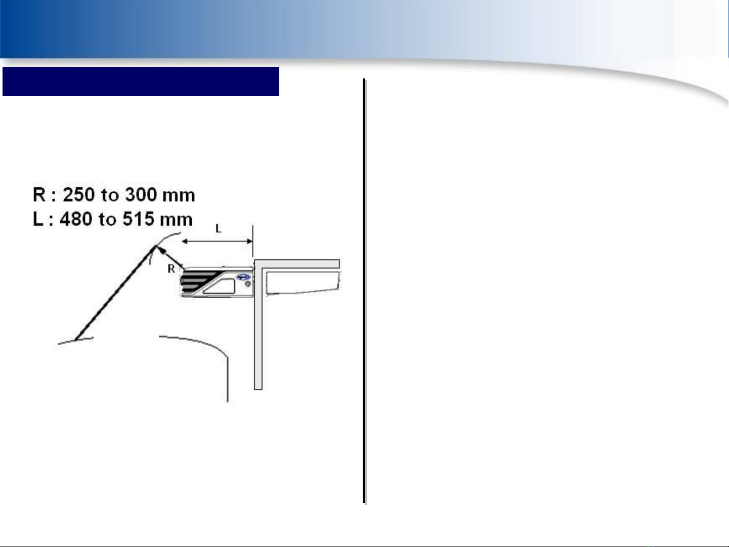
The installation of the deflector on the vehicle
cab should not interfere with the functioning
of the refrigeration equipment
The deflector must not be installed within a
radius of less than 250 mm to 300mm from the
unit
The length between the box and the spoiler
must be at least 480 mm for a Xarios 150 to
515 mm for a Xarios 600
The installation of the deflector must not hinder
accessibility to to the refrigeration unit for
mainenance visits
Access to the power and control boxes must
comply with standard safety conditions
CONDENSOR INSTALLATION
GENERAL INSTALLATION RECOMMENDATION

4UTC Climate, Controls & Security
PROPRIETARY 62-61661-00 Rev B
29th maI 2013
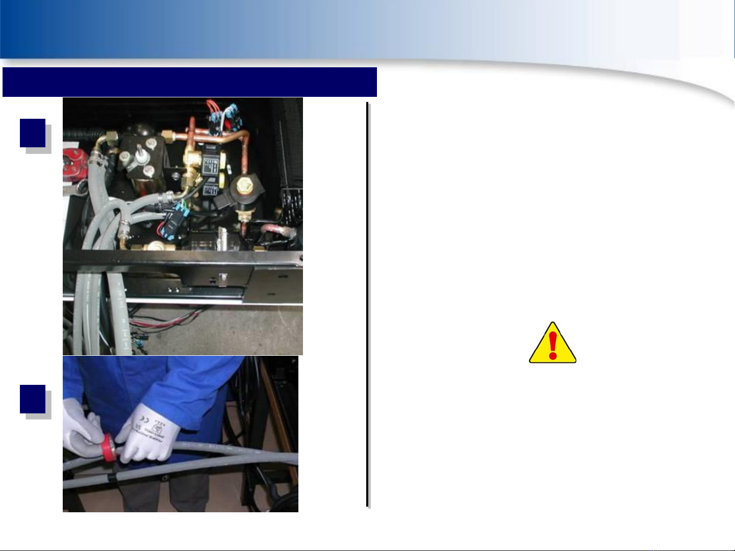
Condenser inlet and outlet
1. Oil separator inlet (« Road » H.P
compressor)
2. « Road » compressor oil return
3. Liquid line
4. Hot gas line
5. Hot gas line N°2 (only for MT° unit)
6. Remove the blanks
7. Warning !
Don’t forget to lubricate the ORS joints with
Carrier POE 68 oil and to put them in their
respective groove
CONDENSER: PREPARATION
1
2
3
4
5
6
7
GENERAL INSTALLATION RECOMMENDATION
5UTC Climate, Controls & Security
PROPRIETARY 62-61661-00 Rev B
29th maI 2013
1. Connect the refrigeration hoses
Low and high pressure lines
Liquid line
Hot gas line
Pass the electrical harnesses and the hoses
inside or outside of the body. (Chose one
option depending on the vehicle
configuration)
2. Important :
Don’t forget to mark the liquid line and the
hot gas line
REFRIGERATION HOSES PREPARATION
1
2
GENERAL INSTALLATION RECOMMENDATION
6UTC Climate, Controls & Security
PROPRIETARY 62-61661-00 Rev B
29th maI 2013
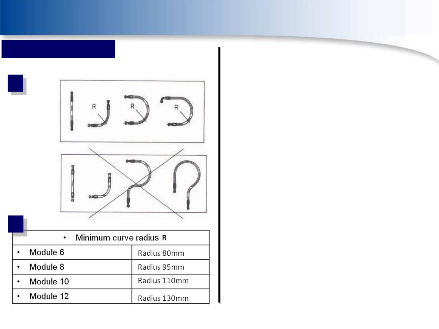
1. Do not twist or curve the hoses.
2. Keep enough length for movement
when the pipes are under pressure.
3. Pipes length can vary between -2% to
+4%.
4. Using elbows and fittings make the
installation easier and increase hose
life.
5. Always insure that minimum radius are
respected. Provide a radius as large as
possible to avoid a restriction in the
hose.
HOSES: MOUNTING
OK
NOT OK
1
5
GENERAL INSTALLATION RECOMMENDATION

7UTC Climate, Controls & Security
PROPRIETARY 62-61661-00 Rev B
29th maI 2013
1. Anti thermal bridge method
By migration and fixing of the refrigeration lines,
please avoid when it’s possible the contact
between both H.P and L.P lines (to reduce heat
transfer phenomenom)
2. Fixing and protecting the lines and
harnesses from the inside and the
outside of the partition
To protect the refrigeration lines and the
electrical harnesses, use trunking
Secure the lines with clamps (RSGU)
Secure the trunking with rivnuts, protect the
trunking termination with conduit
BOX: HARNESS & HOSE
1
2
GENERAL INSTALLATION RECOMMENDATION
8UTC Climate, Controls & Security
PROPRIETARY 62-61661-00 Rev B
29th maI 2013
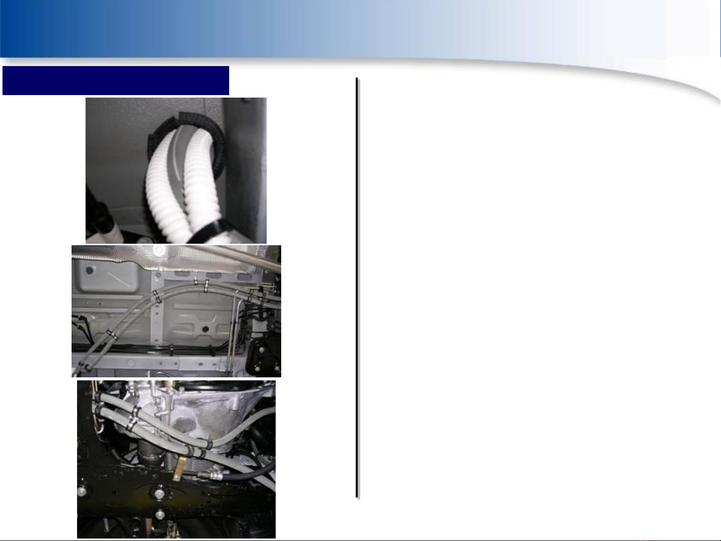
Pipes under the vehicle :
Refrigeration lines have to be :
Fixed at regular intervals with rubber clamps
Kept away as far as possible from each other
to prevent heat transfer
Kept away from any heat source
Protected by grommets (Insulation) were
they pass through the vehicle bodywork
BOX: HARNESS & HOSE
GENERAL INSTALLATION RECOMMENDATION
9UTC Climate, Controls & Security
PROPRIETARY 62-61661-00 Rev B
29th maI 2013
1. Warning !
After the installation of the service valve
connections, please fit service valve caps to avoid
any contamination.
The service valve connections have to be as near
as possible to the road compressor.
2. Road compressor refrigeration
connections
Install the connections on the HP and LP
compressor valves and oil return
OIL RETURN FITTING
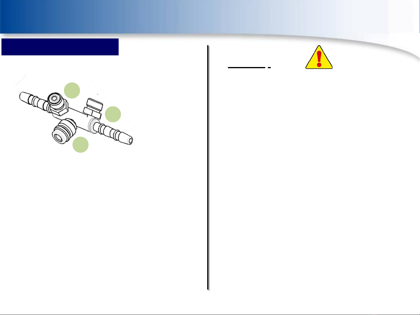
3 ways suction fitting
1
2
3
Oil return recommended location (position 1)
Use the 3 ways fitting corresponding to your
installation instead of the usual LP connection fitting:
•40-60291-50 : IDN 16.1
•40-60291-60 : IDN 12.7
There are 3 ways on this fitting:
1. Oil return connexion
2. Schrader valve for LP manifold
3. Not yet used, put a cap + Oring
GENERAL INSTALLATION RECOMMENDATION

10 UTC Climate, Controls & Security
PROPRIETARY 62-61661-00 Rev B
29th maI 2013
1
2
COMPRESSOR: PREPARATION
COMPRESSOR INSTALLATION
Refrigeration oil is very hygroscopic !
The compressor is under a nitrogen
pressure
•Before the compressor mounting, make sure that
the compressor has an adhesive label fitted,
proof that it is charged with Carrier oil type (no oil
change to do)
•Never leave a compressor crankcase opened
If one of these two points is not respected, it is
imperative to do a compressor oil change and to
restore the right level (see the table ) with Carrier
POE 68 oil from a brand new tank.
This manual suits for next models
9
Table of contents


