UNITED TC250 Manual

United Surface Solutions | 11919 Burke St, Santa Fe Springs, CA 90670 | info@unitedusa.com | (877) 837-4623
Operation & Maintenance Manual
TC250

United Surface Solutions | 11919 Burke St, Santa Fe Springs, CA 90670 | info@unitedusa.com | (877) 837-4623
Table of Contents
1.0 Introduction.........................................................................................................................................................................3
1.1 Method .............................................................................................................................................................................3
2.0 Overview ...............................................................................................................................................................................4
2.1 Components ...................................................................................................................................................................4
2.2 Specifications..................................................................................................................................................................5
3.0 Setup ......................................................................................................................................................................................6
3.1 Placement ............................................................................................................Error! Bookmark not defined.
3.2 Connections ........................................................................................................Error! Bookmark not defined.
4.0 Operation..............................................................................................................................................................................6
4.1 Operation –With Sink ...............................................................................................................................................10
4.2 Operation –Without Sink ........................................................................................................................................10
5.0 Cleaning ..............................................................................................................................................................................11
5.1 Valves ..............................................................................................................................................................................11
5.2 Tanks................................................................................................................................................................................11
6.0 Process Troubleshooting ..............................................................................................................................................11
6.1 Problem: Solution won’t floc...................................................................................................................................11
6.2 Problem: Floc won’t float. ........................................................................................................................................12
6.3 Problem: Sludge clogs filter. ...................................................................................................................................13
6.4 Problem: Sludge seeps through filter..................................................................................................................14
7.0 Preventive Maintenance................................................................................................................................................15
7.1 Shift Inspections ..........................................................................................................................................................15
7.2 Weekly Maintenance .................................................................................................................................................15
7.3 Bi-Weekly Maintenance............................................................................................................................................16
7.4 Monthly Maintenance ...............................................................................................................................................16

United Surface Solutions | 11919 Burke St, Santa Fe Springs, CA 90670 | info@unitedusa.com | (877) 837-4623
1.0 Introduction
All Advanced Water Recycling Systems offered by United Surface Solutions use a chemical process to
remove unwanted contamination from your water so it may be safely recycled. This is different from
purely physical pre-treatments such as clarifiers or osmosis-type systems because we are actually
affecting a chemical change that transforms heavy metals and other toxic substances back into safe
solids, much as they normally occur in nature. Wastewater is comprised of a wide variety of
substances in many different states. Most of these can be determined by looking at the source of the
water. If you are in a deburring shop that is finishing products made of chrome, zinc, and nickel, then
you will have those metals in your wastewater.
United’s units typically use a floc and drop system. A flocculent agent clumps together the solids
floating in the process tank and drops it to the bottoms of the tank for easy removal.
1.1 Method
A dry agent “GR-20” is automatically metered into the processing tank for a simple, and single,
automated process. This is the recommended method of wastewater recycling.
Wastewater treatment with GR-20 takes only minutes, yet several complex chemical reactions occur.
First, the acidic component of the GR-20 causes oily contaminants to coalesce and separate from the
wastewater. Next, the polymeric cationic portion of the formulation attracts any remaining oils and
larger, more highly charged anions. Finally, the basic component activates, precipitating metallic
hydroxides and driving the system to a fully flocculated condition where the cationic polymer
molecules (with any adsorbed oil), metallic ions, and positively charged contaminants are attracted to
the GR-20’s clay particles. Heavy metal cations remaining in solution will exchange with the sodium
on the clay and will bond to the clay platelets by electrostatic forces. The fully reacted mass is a
complex mixture of encapsulated contaminants and waste solids held together by Van der Waals
(weak), as well as electrostatic (strong) forces. The clay particles agglomerate, entrapping and
surrounding suspended solids completely. Pozzolanic reactions also occur, forming cementitious
particles which settle to the bottom of the vessel. The entire microencapsulation process is completed
in just minutes, leaving clear and in most cases sewerable, water.

United Surface Solutions | 11919 Burke St, Santa Fe Springs, CA 90670 | info@unitedusa.com | (877) 837-4623
2.0 Overview
2.1 Components
3-Button
Controls
55 Gallon Process Tank
Notification
Beacon
Optional
Drainage Valves
Optional Sink
55 Gallon Clean Water Tank

United Surface Solutions | 11919 Burke St, Santa Fe Springs, CA 90670 | info@unitedusa.com | (877) 837-4623
2.2 Specifications
Model
TC250
Description
Closed-loop automated water recycling system.
Maximum Capacity
55 Gallons (250 Liters)
Controls
Valves and simple three-button controls.
Average Process Time
25 Minutes
System Type
Closed-loop.
Sewer Connection
Not required.
Machine Construction
304 Stainless steel.
Power Requirements
230-240 VAC ONLY| Single-Phase | 20 Amps
Compressed Air
80 psi (550 kPa) –Dependent on options.
Country of Origin
USA
Warranty
Up to 3 years, determined by component type.
Height
84”
Width
56”
Depth
44.25”
Clearance
2’ Rear+Sides
4’ Front

United Surface Solutions | 11919 Burke St, Santa Fe Springs, CA 90670 | info@unitedusa.com | (877) 837-4623
3.0 Setup
Overview:
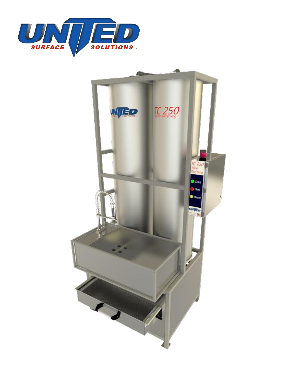
The TC250 is a stand-alone closed loop parts rinsing station. Once filled with fresh water it will recycle
the water many times by utilizing a polymer reactant to remove any suspended solids and cleanse the
water. It is not intended to remove all surfactants, oils or to purify the water. The system consists of a
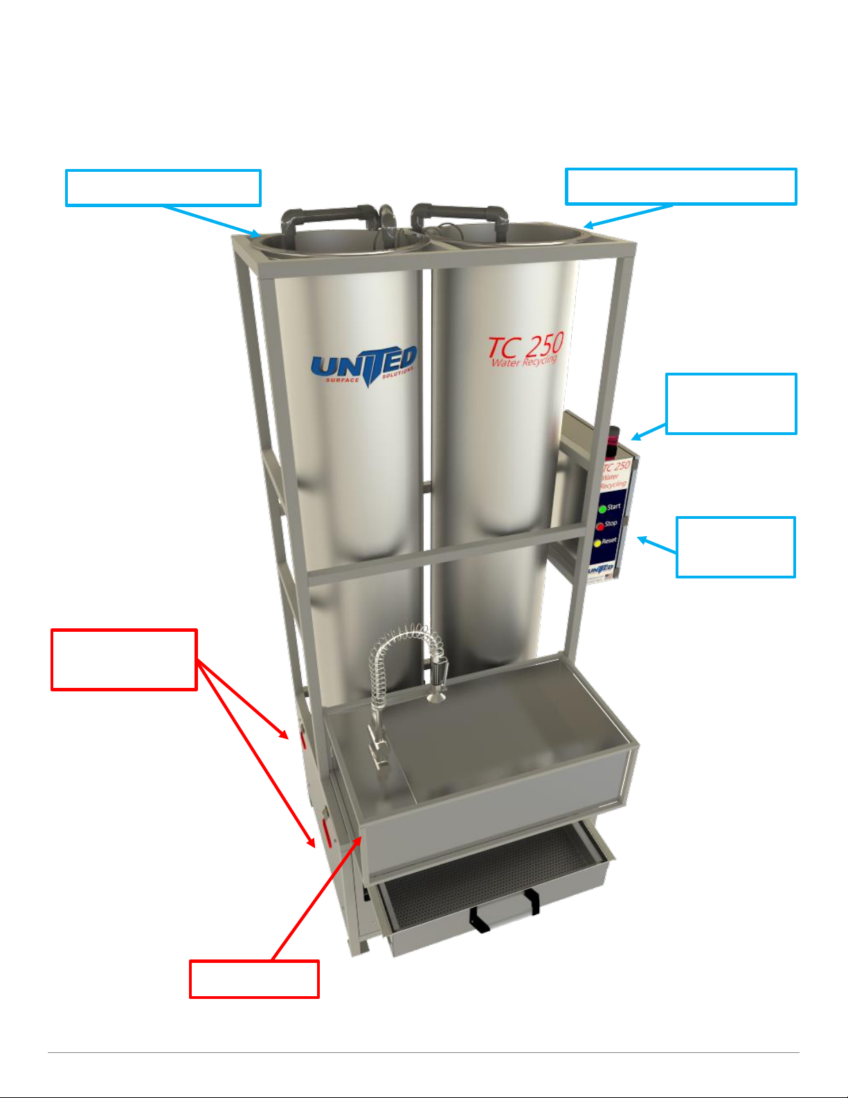
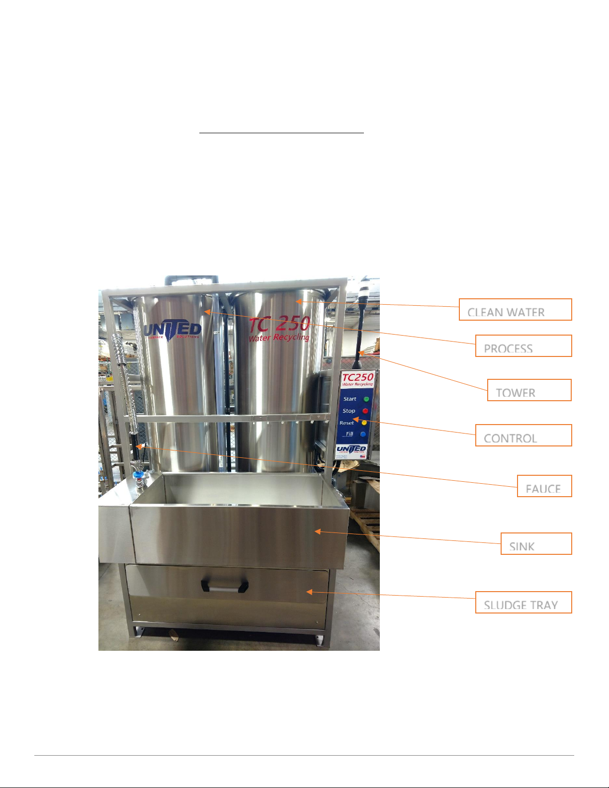
clean water holding tank, pressurized well pump, sink basin with faucet and process tank. When the
spray handle is pressed the water is pumped from the clean water tank to the faucet via the pressure
pump. The water rinses the parts, passes through the sink basin to a gray water sump and then is
pumped into the process tank. The process tank fills and starts the cleaning process. The water is
mixed while a granular reactant is added. This creates a floc gathering suspended solids and cleansing
the water. Microbubbles are added to the floc to causing it to float. After mixing, a rest period is
needed to allow the floc to float to the top and separate from the clean water. The Clean water drains
through a filter media and is pumped back into the clean water tank. The filter media then traps the
floc and allows the sludge to dewater in the sludge tray. Once completely dewatered the floc, now
sludge, can be disposed of. The unit can also be plumbed to include a finishing system in a closed
loop type of configuration.
Start Up:
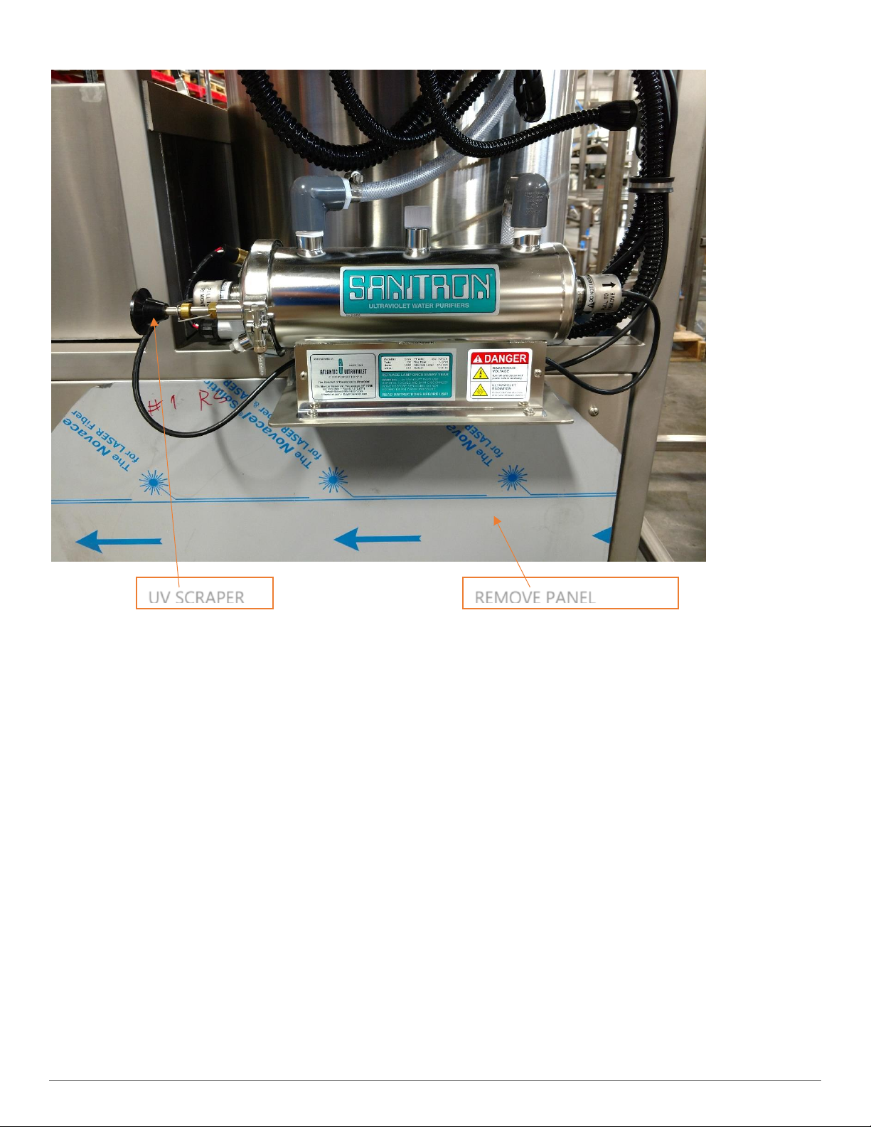
1. Remove all packing material, panel protectors. Cut ties on float switches and hang inside tanks
2. Connect power to 240VAC/60Hz, 1ph, 20-amp source
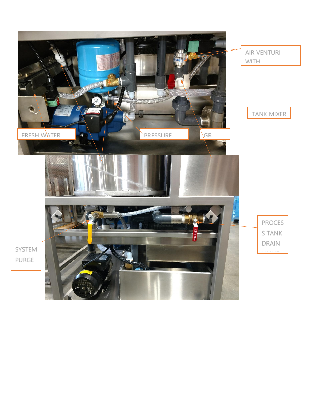
3. Plumb closed loop system according to P&ID
4. Press the Blue Fill button to fill the clean water tank
5. Test run with clean water to prime all pumps and check for leaks
6. Install filter paper in the tray
7. Insert the Intake hose into the box or bucket of GR
Operation:
1. As you use the Sink the TC250 will automatically fill up the Left/Process tank, when it is full the
Red light will come on - this indicates you need to start the process. NOTE: There is a small
reserve of clean water to continue rinsing parts while processing. The clean water pump will
shut off and RED light will activate when the reserve is depleted. NOTE: Flashing Green light
plus RED steady light indicates system processing & reservoir depleted.
2. Press the Start button to begin the process, the Tower Light will turn Flashing Green.
3. Once the batch is complete (approximately 20 mins) the Tower Light will turn Steady Green.
Check that the filter paper is placed properly in the sludge tray.

United Surface Solutions | 11919 Burke St, Santa Fe Springs, CA 90670 | info@unitedusa.com | (877) 837-4623
4. Start draining the tank by opening the Drain Valve approximately 30% allowing the clean water
to drain through the filter paper. After the water is drained and gray sludge start to appear on
the filter paper turn the valve to 100% open until all sludge is drained.
5. When drain is complete turn valve to its closed position and press the Reset button to turn off
the Green Light and reset the system. The Sink is now available for rinsing. NOTE: After the
system is Reset the Start button can be pressed at any time, the process will automatically start
when the process tank becomes full. Green light will Flash to show that the system is active.
Maintenance:
1. Once a week process and drain all clean water from system and replace with fresh water.
2. Flush Process Tank with clean water to remove all sludge and debris.
3. Clean UV Light daily using scraper rod on UV tank.
TOWER
CLEAN WATER
CONTROL
PROCESS
FAUCE
SINK
SLUDGE TRAY

United Surface Solutions | 11919 Burke St, Santa Fe Springs, CA 90670 | info@unitedusa.com | (877) 837-4623
CHECK
AIR VENTURI
WITH
PRESSURE
TANK MIXER
FRESH WATER
GR
SYSTEM
PURGE
VALVE
PROCES
S TANK
DRAIN
VALVE

United Surface Solutions | 11919 Burke St, Santa Fe Springs, CA 90670 | info@unitedusa.com | (877) 837-4623
UV SCRAPER
REMOVE PANEL

United Surface Solutions | 11919 Burke St, Santa Fe Springs, CA 90670 | info@unitedusa.com | (877) 837-4623
4.0 Operation
Processing wastewater with the TC250 is easy and requires very little operator time. Processing a
batch of wastewater is done automatically, except for the quality check and the manual draining
sequence.
4.1 Operation –With Sink
After pouring wastewater into the sink, wastewater pumps into the wastewater holding tank, then into
the process tank. When the process tank reaches capacity, the system alerts the operator that the
process is ready to begin by illuminating its notification beacon. The operator must now press the Start
button to begin the process The system will begin circulating the wastewater while pumping in the
required compounds and adjusting the air and pump flow to separate all suspended and dissolved
solids from the water (this process takes 15-20 minutes).
The system will notify the operator once the process is complete. At this point, it is time to drain the
process tank.
1. Ensure filter paper is in place in the sludge tray.
2. Open the valve underneath the process tank to the half-way point.
3. Slightly dirty water may flow before clean water.
4. After clean water finishes flowing, sludge begins to flow.
5. Fully open the valve and allow the tank to empty into the sludge tray.
6. Open sprinkler valve in process tank to rinse excess dirt.
7. Close all valves.
8. Press Reset on the control panel. Once the sludge has dewatered enough, fold the filter paper
and dispose of the waste.
4.2 Operation –Without Sink
1. Pump wastewater into the left bottom holding tank.
a. Ensure wastewater being pumped in does not exceed 30 GPM (gallons per minute).
2. When the process tank fills, the alert beacon will illuminate like usual. Start the process as
described in “With Sink” operation.

United Surface Solutions | 11919 Burke St, Santa Fe Springs, CA 90670 | info@unitedusa.com | (877) 837-4623
5.0 Cleaning
5.1 Valves
Valves can be flushed out by inserting a hose into a valve and opening it as water flows through.
Valves can also be removed at unions and cleaned manually.
5.2 Tanks
Due to the stainless steel construction, the TC250 will not corrode due to moisture. Tanks can be
rinsed periodically.
6.0 Process Troubleshooting
If you are having trouble processing your water, please refer to the following troubleshooting guide.
6.1 Problem: Solution won’t floc.
If you are having problems getting a floc, lowering or raising the pH will help resolve the issue. For
best results, the PH level should be between 5 and 9 pH. Levels can be adjusted by adding pH+ or
pH- compounds (consult with your United representative). However, if you have determined that
you have a stubborn batch that does not allow easy adjustment of pH, and are having additional
difficulties with the floc, it is likely your wastestream will need re-evaluation by our laboratory.
Please follow these steps.
Cause
Insufficient quantities of GR-20.
Verification
Experimentation.
Correction
Add more GR-20.
Cause
Not enough, or poor mixing.
Verification
Check the bottom of the Process Tank for buildup of excess dry product.
Correction
1. Clean bottom of Process Tank.
2. Allow batch to mix longer.
3. Always add GR by sprinkling into turbulent water, not on top of foam or into
still water.

United Surface Solutions | 11919 Burke St, Santa Fe Springs, CA 90670 | info@unitedusa.com | (877) 837-4623
6.2 Problem: Floc won’t float.
If you have acceptable floc size, but the flakes do not rise to the surface within the usual amount of
time (averages 30 minutes), the following steps may be taken:
Cause
Improper air mixture, or air inlet clogged.
Verification
Disassemble the air intake located next to the pH probe. Always have the
recirculating pump running while the intake is removed to prevent water from
shooting out.
Correction
Clean and inspect the ball check valve, spring and housing for damage or clogging.
Rebuild if able or replace the unit.
Cause
Air Injector solenoid inoperative or clogged.
Verification
Ensure the solenoid valve is operational. Check for intake.
Correction
Clean the solenoid intake or replace the solenoid valve.
Cause
High volume of sludge. If you had to add more product to adjust the pH levels, or
if your waste stream is unusually full of contamination, you may have simply
produced more sludge than usual.
Verification
Visual inspection.
Correction
Give the solution additional time to float. If practical, leave overnight.

United Surface Solutions | 11919 Burke St, Santa Fe Springs, CA 90670 | info@unitedusa.com | (877) 837-4623
6.3 Problem: Sludge clogs filter.
When you begin to drain the clean water, it is important to drain the first 1-3 gallons into a bucket.
A certain amount of floc is trapped in the recirculation piping and must be drained into a bucket
before draining the process tank. By draining this water off, you reduce the danger of clogging the
filter and will increase the amount of time required to drain the entire system. If you have done this
and the Filter still clogs, or you still have dirty water after draining 3 gallons, please read the
following suggestions:
Cause
Attempting to drain before the floc has had a chance to float.
Verification
Visual inspection.
Correction
Experimentation. Allow an additional 15 minutes after addition of flocculent before
attempting to drain.
Cause
Solution did not break completely.
Verification
Observe the water drained into the bucket. If you do not see an identifiable floc, or
the water around the floc looks dirty, then the batch did not break completely.
Correction
See “Solution won’t floc.”
Cause
Solution did not floc completely.
Verification
Check the water drained into the bucket. If you did not get mostly clear water, then
part of the floc did not float. Check again to endure water around the floc is clear.
Correction
If water around the flock is not clear, see “Solution won’t floc.” If water looks clear,
but there seems to be too much floc on the bottom, see “Floc won’t float.”
Cause
Attempting to use a filter more than once.
Verification
Visual inspection. Does the Filter look used?
Correction
Replace the filter. One use per filter is recommended.
Cause
Using a filter device other than one recommended by United Surface Solutions.
Verification
Check with your purchasing department or contact United Surface Solutions.
Correction
Order supplies from United Surface Solutions or its distributors.

United Surface Solutions | 11919 Burke St, Santa Fe Springs, CA 90670 | info@unitedusa.com | (877) 837-4623
6.4 Problem: Sludge seeps through filter.
There will usually be a small amount of floc collecting on the sides of the recycling reservoir; should
this amount become excessive, or if the sludge is moving through the filter, follow these steps:
Cause
Solution did not break completely.
Verification
See “Solution won’t floc.”
Correction
See “Solution won’t floc.”
Cause
Filter damaged.
Verification
Visual inspection. Look for tears, leaks, or other deficiencies.
Correction
Replace filter.
Cause
Incorrect filter.
Verification
Check with your purchasing department or contact United Surface Solutions.
Correction
Order supplies from United Surface Solutions or its distributors.
Cause
Attempting to drain too quickly.
Verification
If the solution has broken well and the filter is in good condition, you may be
draining too quickly and forcing the sludge through the filter.
Correction
Reduce the flow by closing the drain valve to approximately 15 degrees.
Cause
Excessive oil content in wastewater and sludge. An oil content of over 2% is NOT
acceptable and will not process.
Verification
Inspect the sludge for “soupy” or oily appearance and consistency. Inspect dirty
water for oils floating on the surface.
Correction
Install or repair your oil separator device prior to treatment in United Surface
Solutions Advanced Water Recycling Systems, or contact United Surface Solutions
for feasibility of emulsifying oils more completely.
WARNING: This will involve a decrease in the safety of the system due to powerful
acid-base reactions needed for emulsification. If possible, eliminate the oils before
treating.

United Surface Solutions | 11919 Burke St, Santa Fe Springs, CA 90670 | info@unitedusa.com | (877) 837-4623
7.0 Preventive Maintenance
The TC250, like all other state-of-the-art piece of equipment, requires some periodic preventive
maintenance. The preventive maintenance can be performed by the operator assigned to the
equipment or by the maintenance department. Only simple hand tools are required to perform the
required maintenance and it will not be necessary to remove electrical power from the unit.
The one major pre-inspection requirement is that the Process Tank be empty of all water.
There are several specialty items that will be required to perform some of the inspections and tests.
Those items will be listed with the inspection and test requirements.
This manual is broken down by time inspection and maintenance requirements: at the beginning of
each shift, the weekly, the twice-monthly, and the monthly cleanings, inspections, and tests.
7.1 Shift Inspections
1. Check products in each of the containers.
Do not allow the unit to run out of liquid products in mid-process. Always have a spare
container of each type of liquid or dry products on hand so your operation will not have to be
halted while another container is procured.
2. Check all of the product pick-up tubes.
Check for twisted, kinked, or deteriorated tubing. Also, check for signs of leakage or blockage.
Replace any tubing that is suspect.
7.2 Weekly Maintenance
1. Inspect each float switch for freedom of movement.
If needed, clean any residue from the float mechanism and ensure there is complete freedom
of movement.
2. Inspect for sludge buildup on bottom of tanks.
All three tanks (the Holding Tank, the Process Tank and the Clean Water Tank) will need to be
empty for this inspection. The sludge buildup can affect the pH Probe and the Recirculation
Pumps. If needed, clean this sludge residue from all tanks using fresh water only. DO NOT use
any type of liquid or paste cleaners.

United Surface Solutions | 11919 Burke St, Santa Fe Springs, CA 90670 | info@unitedusa.com | (877) 837-4623
7.3 Bi-Weekly Maintenance
The Process Tank will need to be empty for these maintenance procedures, therefore it is
recommended that all of the inspections and cleaning be accomplished simultaneously. Before any
disassembly, lay out clean Filter paper over the Sludge Tray to catch any small parts that may be
dropped.
1. Clean and Inspect the Ball Check Valves (5)
a. The five Ball Check Valves are screwed into the Process Tank Recirculation Manifold.
The four product and one air tube are connected to these valves. They are exposed to
the Process Tank water and therefore will have a tendency to get dirty.
b. The Ball Check Valve can be disassembled without removing it from the manifold. The
tube-check valve connector fitting can be unscrewed from the manifold fitting, leaving
the manifold fitting installed in the manifold. This is recommended to prevent wear on
the fitting and possible leakage. The cap, spring and ball are installed within the tube-
connector check valve fitting.
c. When the tube-connector check valve fitting is loosened and removed, the cap, spring
and ball can be removed from the fitting for easy inspection and cleaning. Cleaning is
done with only clean fresh water and a soft non-abrasive cloth. Also inspect and clean
the o-ring inside and the o-ring on the outside of the tube - connector check valve
fitting.
d. The tube cap can be loosened to inspect the tube end if signs of leakage are present.
As corrective action, the tube can be trimmed and reinstalled.
7.4 Monthly Maintenance
1. Tank Cleaning
All of the tanks need to be rinsed at least monthly to remove any residue on the bottom and
sides of the tanks. The Clean Water Reservoir drain has a screen installed that needs to be
cleaned monthly to ensure sufficient flow of clean water. The pressure from a water hose is
sufficient to clean the tanks. Do not use any type of liquid or paste cleaners.
2. Clean Water Reservoir Pressure Pump Check Valve
The check valve can be removed from the unit by loosening the two couplings, one up-stream
and one down-stream of the check valve. Flush the valve with fresh water to clean and ensure
good flow. Also, inspect to ensure that a back-flow of water will push the check valve close
and not allow the water to pass.
Table of contents
Other UNITED Industrial Equipment manuals