Project Specications
6
United Industries, Inc.
P.O. Box 58
Sterling, KS 67579
800-835-3272 • 620-278-3160
Fax 800-500-3115 • 620-278-3115
www.towerflo.com
Form TFH-PSP-1/3:2/17
Data presented here is the best available at the
time of publicaton. United Industries and/or its
representatives assume no liability for its use.
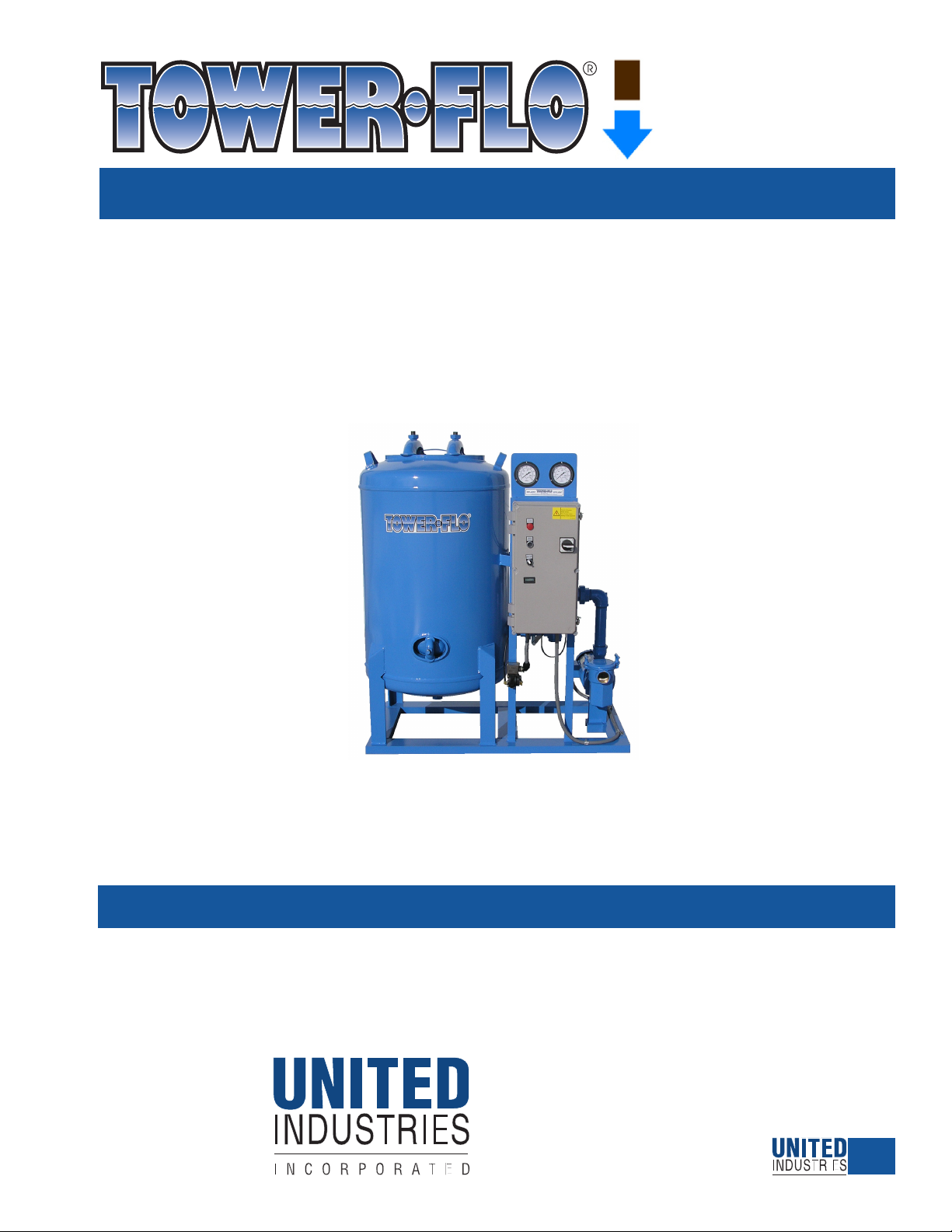
Series
TFH
TOWER-FLO® Series TFH self-contained filter plants shall consist of the following major components: base, pump, motor,
strainer, facepiping, valve, controls, and filter vessel. The system shall be shipped as a complete factory assembled and tested
unit. Filter media shall be shipped with the unit for field installation.
Project: ________________________________________________________ Date: ______________________
The TOWER-FLO Series TFH Model being specified for this project is a TFH-____ with a maximum filter rate of _____ GPM.
___ unit(s) is(are) specified and each unit shall be equipped with the following components:
COMPONENT SPECIFICATION
BASE ___ Standard: Structural steel channel and plate, primed and coated.
PUMP ___ Standard: TFH-18, -24, -30: Self-priming, close grain cast and machined brass volute, impeller, and pump-to-
motor coupling; close coupled to the motor; and capable of ____ GPM at ____ feet TDH.
___ Standard: TFH-36: Flooded suction, machined cast iron volute, bronze fitted, close coupled to the motor
and capable of ____ GPM at ____ feet TDH.
___ Option: TFH-36: Self-priming pump, machined cast iron volute, bronze fitted, close coupled to the motor
and capable of ____ GPM at ____ feet TDH.
MOTOR ___ Standard: TFH-18, -24, -30: TEFC, heavy gauge rolled steel case, NEMA 56C frame, Class F insulation,
double shielded prelubricated ball bearings; UL®and CSA®listed; ____ HP; and at the follow-
ing VAC, phase and Hz: ___________________.
___ Standard: TFH-36: TEFC, heavy gauge rolled steel case, NEMA 145JM frame, Class F insulation, double
shielded prelubricated ball bearings; UL®and CSA® listed; ____ HP; and at the following VAC,
phase and Hz: ___________________.
___ Option: 575V.
STRAINER ___ Standard: TFH-18, -24, -30: Basket type, brass body, ABS basket, brass cover with o-ring, held in place
by two brass lockhandles.
___ Option: TFH-18, -24, -30: Delete strainer on installations where inlet pressure exceeds 30PSI.
___ Standard: TFH-36: Cast iron body; stainless steel basket; cast iron cover with gasket, held in place with a
yoke and bolt clamp (60 PSI @ 150˚ F).
FACEPIPING ___ Standard: Steel; backwash sight glass; influent / effluent pressure gauges, 0-160 psi, liquid-filled
___ Option: Type 304 Stainless Steel (with brass or stainless steel valves).
___ Option: Fresh water backwash from municipal water supply; includes facepiping modifications, flow
control valve for field installation; end-user responsible for the addition of pressure regulator
(maximum 30 psi) and/or backflow preventer, if required.
___ Option: Fresh water backwash from static water supply using pump to assist.
VALVES ___ Standard: Brass, 3-way ball valves, with electric actuation.
___ Option: Stainless steel (with steel or stainless steel facepiping).
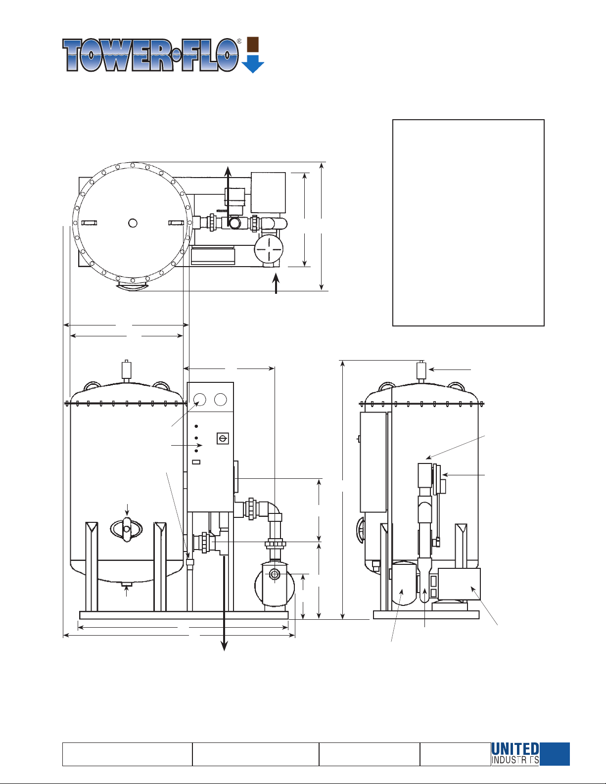
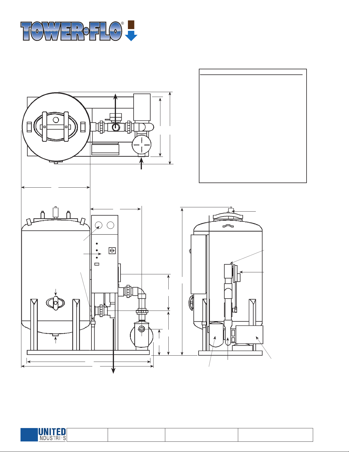
141 GPM MAX FLOW RATE 100 PSI WORKING PRESSURE
Model Base HP Max TDH Full Load Amp Draw Media Operating
Number Dimensions GPM Ft. Single Phase Three Phase Area Vol Weight
S.F. 115V 208V 230V S.F. 208V 230V 460V SqFt CuFt* in Lbs
TFH-18 16.75" x 38" 1 35 65 1.15 12.0 6.6 6.0 1.15 3.2 3.6 1.8 1.8 4.0
TFH-24 22" X 46" 1.5 65 50 1.0 17.0 8.8 8.5 1.15 4.4 4.2 2.1 3.14 7.0 2488
TFH-30 26" X 52" 3 100 45 1.0 - 14.0 14.2 1.15 8.1 8.0 4.0 5.0 9.0 2957
TFH-36 30" X 58" 3 141 45 1.15 - - - 1.15 9.1 8.3 4.1 7.0 14.0 3910
*1 Cubic foot of media = 100 lbs.