Unitek 9100 Series User manual

USER’S MANUAL NO. 990-606
REVISION B: February 2000
OPERATION AND MAINTENANCE MANUAL
FOR THE
9100 SERIES SEMI-AUTOMATIC
HIGH PRECISION
REFLOW SOLDERING SYSTEM

9100 SERIES REFLOW SOLDERING SYSTEM
ii 990-606
Copyright © 1999-2000, Unitek Miyachi Corporation
The engineering designs, drawings and data contained herein are the proprietary work of
UNITEK MIYACHI CORPORATION and may not be reproduced, copied, exhibited or
otherwise used without the written authorization of UNITEK MIYACHI CORPORATION.
Printed in the United States of America
Revision Record
Revision EO Date Basis of Revision
A 17789 2/99 Original publication
B 18118 2/00 Production release

9100 SERIES REFLOW SOLDERING SYSTEM
990-606 iii
FOREWORD
Thank you for purchasing a Unitek Precision System 9100 Series Semi-Automatic High Precision Reflow
Soldering System.
Upon receipt of your equipment, please thoroughly inspect it for shipping damage prior to its installation.
Should there be any damage, please immediately contact the shipping company to file a claim, and notify us
at:
Unitek Precision Systems
1820 South Myrtle Avenue
P.O. Box 5033
Monrovia, CA 91017-7133
Telephone: (626) 303-5676
FAX: (626) 358-8048
e-mail: info@unitekprecisionsystems.com
The purpose of this manual is to supply operating and maintenance personnel with the information needed
to properly and safely operate and maintain Unitek Precision System's 9100 Series Reflow Soldering
System.
The System consists of three major units: the workstation, the Uniflow® Pulsed Thermode Control
(Uniflow), and the Bonding Head. The latter two items have their own manuals. (See table 1-1) Therefore,
you will need both the Uniflow and Bonding Head manuals, in addition to this manual, to operate and
maintain the system. (The Bonding Head, referred to here, is called a Weld Head or Reflow Solder Head in
its manual.)
We have made every effort to ensure that the information in this manual is accurate and adequate.
Should questions arise, or if you have suggestions for improvement of this manual, please contact us at the
above location/numbers.
Unitek Miyachi Corporation is not responsible for any loss due to improper use of this product.

9100 SERIES REFLOW SOLDERING SYSTEM
iv 990-606
SAFETY NOTES
This instruction manual describes how to operate, maintain and service the 9100 Reflow Soldering System,
and provides instructions relating to its SAFE use. Two companion manuals, as listed in table 1-1, provide
detailed information for the Uniflow and the Bonding Head. Procedures described in these manuals MUST
be performed, as detailed, by QUALIFIED and TRAINED personnel.
For SAFETY, and to effectively take advantage of the full capabilities of the workstation, please read these
instruction manuals before attempting to use the workstation.
Procedures other than those described in these manuals or not performed as prescribed in them, may expose
personnel to electrical, burn, or crushing hazards.
After reading these manuals, retain them for future reference when any questions arise regarding the proper
and SAFE operation of the workstation.
Please note the following conventions used in this manual:
WARNING: Comments marked this way warn the reader of actions which, if not followed, might result in
immediate death or serious injury.
CAUTION: Comments marked this way warn the reader of actions which, if not followed, might result in
either damage to the equipment, or injury to the individual if subject to long-term exposure to the indicated
hazard.

9100 SERIES REFLOW SOLDERING SYSTEM
990-606 v
CONTENTS
CHAPTER 1: System Description....................................................................................................... 1-1
Section I: Features ...................................................................................................................... 1-1
Features............................................................................................................................ 1-1
Section II: System Components.................................................................................................. 1-2
Major Components........................................................................................................... 1-2
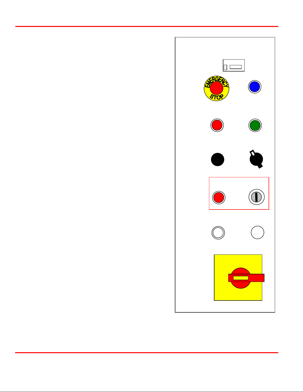
Controls and Indicators.................................................................................................... 1-4
Control Panel ....................................................................................................... 1-4
Tabletop Controls ................................................................................................ 1-5
Access Doors ................................................................................................................... 1-6
Electrical Connectors....................................................................................................... 1-6
CHAPTER 2: Getting Started............................................................................................................. 2-1
Section I: Planning for Installation............................................................................................. 2-1
Space Requirements......................................................................................................... 2-1
Power Requirements........................................................................................................ 2-1
Compressed Air Requirements........................................................................................ 2-1
User Manufactured Jigs, Mounting Hole Requirements ................................................. 2-1
CHAPTER 3: Operating Instructions ................................................................................................ 3-1
Section I: Operating Precautions ................................................................................................ 3-1
General Operator Safety .................................................................................................. 3-1
Set-Up Safety................................................................................................................... 3-1
Section II: Preparing for Operation ............................................................................................ 3-1
Pre-Operational Checks................................................................................................... 3-1
Turning the Equipment On .............................................................................................. 3-2
Section III: Operation ................................................................................................................ 3-2
Set-Up.............................................................................................................................. 3-2
Installing the Jigs................................................................................................. 3-2
Aligning the Bonding Head................................................................................. 3-3
Establishing the Reflow Schedule ....................................................................... 3-5
Operation ......................................................................................................................... 3-5
Section IV: Shutdown................................................................................................................. 3-6
Emergency Shutdown...................................................................................................... 3-6
Normal Shutdown............................................................................................................ 3-6

9100 SERIES REFLOW SOLDERING SYSTEM
vi 990-606
CHAPTER 4: User Maintenance ........................................................................................................ 4-1
Section I: Precautions ................................................................................................................. 4-1
General Operator Safety .................................................................................................. 4-1
Section II: Operator Maintenance............................................................................................... 4-1
Preventive Maintenance Schedule................................................................................... 4-1
Clean Vacuum Generator Filter...................................................................................... 4-2
Grease Rotary Table Ring Gear and Refill Lubricators .................................................. 4-2
Check Play in Unislide and Adjust.................................................................................. 4-4
Clean Bonding Edge of Thermode .................................................................................. 4-4
APPENDIX A: Specifications.............................................................................................................. A-1
INDEX.....................................................................................................................................................Index-1
ILLUSTRATIONS
Figure Title Page
1-1 9100 Series Reflow Soldering System, Major Components........................................................ 1-2
1-2 Control Panel .............................................................................................................................. 1-4
1-3 Workstation Tabletop .................................................................................................................. 1-5
1-4 Location of Access Panels and Electrical Connectors................................................................. 1-6
3-1 Installing a Typical Jig................................................................................................................. 3-3
3-2 Making the Unislide Adjustments ............................................................................................... 3-4
3-3 Making Co-Planarity Adjustment................................................................................................ 3-5
3-4 Aligning Items to be Bonded with Micrometer........................................................................... 3-6
4-1 Removing Vacuum Generator from Workstation........................................................................ 4-2
4-2 Removing Filter Assembly from Vacuum Generator.................................................................. 4-2
4-3 Removing Filter from Filter Assembly........................................................................................ 4-2
4-4 Removing Vacuum Generator Hose to the Hub.......................................................................... 4-3
4-5 Removing Rotary Table............................................................................................................... 4-3
4-6 Lubricating Gears and Lubricators .............................................................................................. 4-3
4-7 Adjustment of Gib Strip............................................................................................................... 4-4
A-1 Outline Drawing of Workstation ................................................................................................. A-3
A-2 Hole Pattern for Typical Segment of Rotary Table..................................................................... A-4
TABLES
Figure Title Page
1-1 Technical Manuals for Use with the 9100 Series Reflow Soldering System.............................. 1-3
4-1 Preventive Maintenance Schedule............................................................................................... 4-1
A-1 Specifications .............................................................................................................................. A-2

9100 SERIES REFLOW SOLDERING SYSTEM
990-606 1-1
CHAPTER 1
SYSTEM DESCRIPTION
Section I: Features
Features
The 9100 Series Semi-automatic High Precision Reflow Soldering System, herein called the reflow
soldering system, is a stand-alone workstation designed for high-volume, repeatable reflow soldering
operations, with the following features:
Rotary turntable allows simultaneous loading and bonding operations.
Flexible programming for up to six product nests and three different product types.
Software is configured to allow automatic changeover between product types or variants.
Uniflow®pulse-heated soldering control provides temperature and timing control for the thermode
heating.
Optimized thermode heating and automatic cooling allow for fastest production rates.
Twin start operator controls and interlock guard for operator safety.
Precision slide head adjustment and manual override for ease of set-up.

CHAPTER 1: SYSTEM DESCRIPTION
9100 SERIES REFLOW SOLDERING SYSTEM
1-2 990-606
Section II: System Components
Major Components
The 9100 Series Semi-automatic High Precision Reflow Soldering System comprises three major units: the
actual workstation with its rotary turntable (workstation), a Uniflow Pulsed Thermode Control (Uniflow),
and a bonding head. (In the separate manual for the bonding head, it is usually referred to by the more
generic term “weldhead.”) The location of these major units is shown in figure 1-1.
Figure 1-1. 9100 Series Reflow Soldering System, Major Components

CHAPTER 1: SYSTEM DESCRIPTION
9100 SERIES REFLOW SOLDERING SYSTEM
990-606 1-3
The workstation with its rotary turntable is described in this manual.
The Uniflow Pulsed Thermode Control brings precise temperature and time control to heat the thermodes.
Depending on which configuration you ordered, you may have the standard Uniflow or the Remote
Operation Control (ROC) unit. The manual for those units are listed in table 1-1 and is considered part of
the technical manual suite for your equipment.
Depending on which configuration you ordered, you will have one of three Bonding Heads, 87SA/24,
84SA/24, or 180SA/24. You will receive the respective manual for your module, as shown in table 1-1, as
part of your technical manual suite.
Related manuals, which you may wish to procure from Unitek Precision Systems, are Uniflow Advanced
Serial Datacom Communications Interface, Manual No. 990-341; and Pulse Heated Thermode Selection
Guide, No. 991-410. Please consult your Unitek Precision Systems representative to obtain these manuals.
Table 1-1. Technical Manuals for Use with the 9100 Series Reflow Soldering System
Component Type Technical Manual Number
Workstation 990-606
Uniflow Remote or Manual 990-225
Bonding Head 87SA/24 or 84SA/24 990-121
180SA/24 990-125
Optional Reference Manuals
(see above)
Communications Interface 990-341
Thermode Selection Guide 991-410

CHAPTER 1: SYSTEM DESCRIPTION
9100 SERIES REFLOW SOLDERING SYSTEM
1-4 990-606
Controls and Indicators
Control Panel
The control panel, shown in figure 1-2, contains the
following controls and indicators.
1BONDING CYCLES COMPLETED indicator -
(Grey LCD indicator with built-in reset button)
Indicates number of bonded parts.
2 EMERGENCY STOP switch - (Red mushroom-head
pushbutton) Turns off power in an emergency. Not
intended for normal use.
3 RESET switch/indicator - (Blue pushbutton with built-in
indicator) Used to reset guard switches on initial startup or
after an emergency stop. The blue indicator lights when
resetting is required; the light goes out after the RESET
switch is pressed.
4 CONTROL OFF switch - (Red pushbutton) Used to
remove power to the control circuits and electrical sensors
and switches.
5CONTROL ON switch/indicator - (Green pushbutton with
built-in indicator) Used to apply power to the control circuits
and electrical sensors and switches.
6 MONITOR/CAMERA Not used.
7JIGS IN PLACE switch - (Four-position rotary switch)
Used to select either jig sets 1, 2, or 3, or all three jig sets.
8GUARD OVERRIDE indicator - (Red indicator) Lights
when override is in effect.
9GUARD OVERRIDE key switch - Allows operation of the
rotary table and jigs (for indexing) when the guard door is
open. Permits access to MANUAL BOND switch for set-up.
COUNTS
BONDING CYCLES
COMPLETED
RESET
CONTROL ON
CONTROL OFF
MONITOR/CAMERA
ON/OFF
JIGS
IN PLACE
1
23
ALL
GUARD OVERRIDE
TABLE
INDEX MAINS ON
MAIN ISOLATOR
1
O
Figure 1-2. Control Panel

CHAPTER 1: SYSTEM DESCRIPTION
9100 SERIES REFLOW SOLDERING SYSTEM
990-606 1-5
10 TABLE INDEX switch - (White pushbutton) Used in conjunction with the left hand READY TO INDEX
switch (see workstation controls) to index the table without activating the bonding head. Is useful for
removing the last unit from the workstation at the completion of a job.
11 MAINS ON indicator - (White indicator) Lights to indicate that the MAIN ISOLATOR switch is on and
power is applied to the workstation.
12 MAIN ISOLATOR switch - (Red rotary switch) Used to apply main power to the workstation (1). The (0)
position removes the power.
Tabletop Controls
There are three controls on the workstation tabletop, one of which is a pair, as shown in figure 1-3.
Figure 1-3. Workstation Tabletop
1READY TO INDEX switches/ indicators - (Green pushbuttons with built-in indicators) The two
green indicators light when the bonding head is clear of the jig. At this time the turntable may be
safely rotated to the next station. This is done by the operator simultaneously pressing both switches
(thus preventing injury to the operator’s hands from the motion of the rotary table).
2BOND FAULT indicator - (Red indicator) Indicates a bonding failure due any one of several
faults, as set up with the Uniflow, such as the temperature of the Bonding Head not being within set
limits
3MANUAL BOND switch - (Blue pushbutton) Used to cycle the Bonding Head without turning the
rotary table. Usually used only for set-up.
NOTE: It is advisable to set the Uniflow HEAT/NO HEAT switch to NO HEAT during set-up to
prevent damage to the jig.

CHAPTER 1: SYSTEM DESCRIPTION
9100 SERIES REFLOW SOLDERING SYSTEM
1-6 990-606
Access Doors
The workstation has three points of access, as shown in figure 1-4. The work area enclosure can be
accessed for servicing by either lifting the front half of the enclosure, or opening the access door in the rear
of the closure. These access points are monitored with interlock switches to prevent operation of the unit
when they are opened (unless the GUARD OVERRIDE key switch is activated).
On the right-hand side of the workstation, a pair of lockable doors allow access to the electronics for
installation and servicing.
Electrical Connectors
Figure 1-4 shows the location of external connectors for connecting equipment (including the Uniflow and
the Bonding Head).
Figure 1-4. Location of Access Panels and External Electrical Connectors
110 VOLT CONNECTOR

9100 SERIES REFLOW SOLDERING SYSTEM
990-606 2-1
CHAPTER 2
GETTING STARTED
Section I: Planning for Installation
NOTE: Installation will be done by a Unitek Precision Systems representatives, but you must have the
following accommodations in place to permit installation.
Space Requirements
We recommend that the workstation be installed in a well ventilated area that is free from excessive dust,
acids, corrosive gasses, salt and moisture. Allow adequate space around the workstation for power cabling
runs, and additional space in front for the operator.
Outline drawings of the workstation are included in Appendix A. The approximate dimensions of the
workstation are:
Width: 49 in. (1245 mm) + 17 in. (432 mm)*
Depth 43 in. (1092 mm) + 17 in. (432 mm)*
Height 60 in. (1524 mm) + 28 in. (702 mm )*
* Additional space required to open access doors.
The floor surface must be able to support the weight of the workstation and the operator. The workstation,
with all options, weighs 483 lbs (1064kg).
Power Requirements
Power requirements will vary depending on your configuration. The minimum voltage requirements are:
120 VAC (±5%), 16A, single phase, 50/60Hz (for 120V Uniflows)
240 VAC (±5%), 16A, single phase, 50/60Hz (for 240V Uniflows; 120V ac power is also required)
Compressed Air Requirements
The workstation requires a source of 80-100 p.s.i. (5.6-7.0kg/cm2) compressed air. The workstation is
equipped with a c” NPT – 3inch tube push-in fitting
User Manufactured Jigs, Mounting Hole Requirements
To assist the user in making specific jigs, a hole pattern of the rotary table is provided in Appendix A.


9100 SERIES REFLOW SOLDERING SYSTEM
990-606 3-1
CHAPTER 3
OPERATING INSTRUCTIONS
Section I: Operating Precautions
General Operator Safety
WARNING: Do not wear loose clothing or jewelry when operating the workstation. It could be caught in
the rotary table or other moving parts.
The workstation is provided with an interlock system that prevents the operator from coming into contact
with most hazards. The requirement for using both hands to move the rotating table, prevents the hands
from being hurt during that action.
Set-Up Safety
WARNINGS
Set-up should only be done by an experienced and trained individual. During set-up, the GUARD
OVERRIDE key switch may be activated. (The GUARD OVERRIDE red indicator will warn the operator
of this condition.) With the GUARD OVERRIDE activated, the safety shields may be lifted with full
operation unhindered. Therefore, the operator is in danger of burning, crushing, and entanglement hazards.
Wear safety goggles any time you are operating the workstation with the safety shield open.
Do not wear loose clothing or jewelry when working around the workstation whether the safety shield is
open or closed
Before performing set-up, read the separate manuals on the Uniflow and the Bonding Head, listed in table 1-
1. Particularly note the specific hazards associated with those components.
Section II: Preparing for Operation
Pre-Operational Checks
Before operating the equipment, verify that the power and compressed air connections are made as
described in Chapter 2.
Verify that the Uniflow is connected to the appropriate connector at the rear of the workstation.

CHAPTER 3: OPERATING INSTRUCTIONS
9100 SERIES REFLOW SOLDERING SYSTEM
3-2 990-606
Turning the Equipment On
NOTE: Be sure all shields are closed prior to applying power.
To apply power to the unit, perform the following steps. If any of the indicators do not light or go out, as
described, contact your Unitek Precision Systems representative.
1At the bottom of the control panel, turn the red MAIN ISOLATOR switch fully clockwise to the 1
position. Observe that the white MAINS ON indicator lights.
2Press the green CONTROL ON pushbutton near the top of the control panel. The green CONTROL ON
and blue RESET indicators will light.
3Press and hold the blue RESET pushbutton until the rotary table begins to turn. The blue RESET
indicator will go out, and the rotating table will turn until it finds the appropriate jig position (as set by
the JIGS IN PLACE switch). If all conditions are correct, the Uniflow will also turn on at this time.
(See Uniflow manual for conditions that would keep it from turning on.) The workstation is now ready
for set-up adjustments.
Section III: Operation
Set-Up
WARNING: Set-up is done with the safety guards open. It should only be done by a trained individual
wearing safety glasses and no loose clothing or jewelry.
Set-up consists of three actions: installing the necessary jigs, aligning the Bonding Head and thermode to
the correct bonding position, and establishing the reflow schedule on the Uniflow.
To perform set-up, use the key to turn the GUARD OVERRIDE key switch clockwise. Verify the red
GUARD OVERRIDE indicator lights.
Installing the Jigs
The workstation rotary table can hold three pairs of jigs, allowing quick changeover from one operation
to another. After determining what jigs will be used, mount a pair of jigs in opposing jig mounts.
To mount a jig, perform the following steps:
1 Set the JIGS IN PLACE switch to the appropriate position, depending on what your jig set-up will
be.
2Turn on the unit power, as described above.
NOTE: Any time the position of the JIGS IN PLACE switch is changed, you must reset the unit.
This is done by pressing and holding the blue RESET pushbutton until the rotary table begins to
turn.
3Simultaneously press the white TABLE INDEX pushbutton and the left-hand green READY TO
INDEX pushbutton. The rotary table will move to the next position, as determined by the setting of
the JIGS IN PLACE switch. Continue to do this until the position at which you will be mounting the
first jig is in front of you.

CHAPTER 3: OPERATING INSTRUCTIONS
9100 SERIES REFLOW SOLDERING SYSTEM
990-606 3-3
4Align the jig on the rotating table using alignment pins, if present. Mount the jig with four socket
head cap screws. (See figure 3-1)
NOTE: Set-ups are customized for each customer; alignment pins may not be present and you may not
use four screws for attaching your jig.
Figure 3-1. Installing a Typical Jig
NOTE: There are three paired positions on the rotary table, marked JIG 1, JIG 2, and JIG 3. You may
mount up to three pairs at any one time and use any set pairs. Just be sure that the identical jigs (pairs)
are opposite each other in identically marked locations.
5Repeat step 1 until the next location at which a jig will be installed is in front of you. Repeat step 2.
6Continue as in steps 3 and 4 until all jigs are mounted.
Aligning the Bonding Head
The Bonding Head adjustments are found in the appropriate Bonding Head technical manual, cited in
table 1-1 of this manual.. Alignment of the Bonding Head for your specific bonding task is performed
as follows.
1 Place a sample piece to be bonded into the nest of one of the jigs, and move it into position under the
Bonding Head. As indicated above, this is done by simultaneously pressing the white TABLE
INDEX pushbutton and the left-hand green READY TO INDEX pushbutton.

CHAPTER 3: OPERATING INSTRUCTIONS
9100 SERIES REFLOW SOLDERING SYSTEM
3-4 990-606
2Release the black Unislide locking knob on the side of the Bonding Head (figure 3-2), and turn the
Unislide adjustment knob that moves the Bonding Head forward and backward until the thermode is
aligned in that axis. After alignment is complete, re-lock the Bonding Head.
Figure 3-2. Making the Unislide Adjustments
NOTE: Alignment can be visually checked by releasing some of the air pressure on the “up” air valve
to allow the thermode to lower to the workpiece.
3Place a piece of pressure-sensitive paper on the workpiece in the jig.
NOTE: Be sure the HEAT/NO HEAT switch on the bottom right-hand side of the Uniflow front panel
is in the NO HEAT position.
4Press the blue MANUAL BOND pushbutton to cycle the Bonding Head. Remove the pressure-
sensitive paper and observe if the pressure was equally distributed from left to right (figure 3-3).
5If the pressure is not equally distributed, adjust the co-planarity of the Bonding Head, as described
below, and repeat step 4, until equal pressure distribution is attained (figure 3-3).
aPlace a prop under the Bonding Head so it does not fall when the attaching bolts are loosened.
bSlightly loosen the two attaching bolts of the Bonding Head.
cLoosen the locking nut on each of the two co-planarity adjustment knobs (one on each side of
the Bonding Head).
dAdjust the two co-planarity knobs (one inward, the other outward) to adjust the co-planarity.
eTighten the two locking nuts and the two Bonding Head attaching bolts, remove the prop, and
repeat steps 3 and 4.

CHAPTER 3: OPERATING INSTRUCTIONS
9100 SERIES REFLOW SOLDERING SYSTEM
990-606 3-5
Figure 3-3. Making Co-Planarity Adjustment
Establishing the Reflow Schedule
The reflow heating schedule is found in the Uniflow User’s Manual, cited in table 1-1 of this manual.
Operation
To operate the workstation, perform the following steps:
1Verify with your supervisor that all set-up procedures have been performed, as described above and in
the Uniflow User’s Manual, cited in table 1-1 of this manual.
2Set the JIGS IN PLACE switch to the appropriate position depending on the set-up.
3If the unit is not currently turned-on, perform the turn-on procedure described above.
4Turn on the Uniflow, as described in the Uniflow User’s Manual.
5If you wish to keep track of the number of items bonded, press the reset switch on the BONDING
CYCLES COMPLETED LCD display.
NOTE: Each jig set up is customized. Workpieces may be held in place by nests, alignment pins, or
vacuum. Some jigs may have micrometer alignment controls. Your supervisor will instruct you on the
appropriate procedure for your set-up.
6Place the two items to be bonded together into the respective places in the jig.
7If required, use the jig micrometer to align the two items (figure 3-4).
Co-planarity requires adjustment
(The Adjustment Knob on the side
that is lighter needs to be turned
counterclockwise, and the other side
clockwise.)
CW
CCW
Good co-planarity adjustment

CHAPTER 3: OPERATING INSTRUCTIONS
9100 SERIES REFLOW SOLDERING SYSTEM
3-6 990-606
8Verify that the two green READY TO INDEX indicators are lit, and press both of them simultaneously.
The rotary table will rotate the pieces to be bonded to the reflow position under the Bonding Head, and
the Bonding Head will cycle to bond the items.
9While the items are being bonded, repeat steps 6 and 7, above, at the opposing jig. When the bonding
process is complete, the two green READY TO INDEX indicators will re-light. As soon as you are
ready, again press the two READY TO INDEX pushbuttons. The rotary table will rotate the two new
pieces to be bonded to the position under the Bonding Head, and the Bonding Head will cycle to bond
the items.
10 During this time, remove the two bonded items, inspect them, and insert two new items to be bonded.
11 Continuously repeat steps 9 and 10 until your job is complete. To remove the final piece,
simultaneously press the white TABLE INDEX switch on the control panel and the green left-hand
READY TO INDEX switch on the worktable.
Section IV: Shut Down
Emergency Shutdown
For any emergency the unit can be quickly shut down by pressing the red EMERGENCY STOP switch.
After clearing the problem, the unit must be reset by pressing the blue RESET pushbutton. If necessary,
turn the MAIN ISOLATOR switch counterclockwise to the O position. If you do this, you must perform a
complete system turn-on cycle.
Normal Shutdown
For normal shutdown, perform the following steps:
1Remove the last bonded unit from the workstation.
2Press the red CONTROL OFF pushbutton.
3Set the MAIN ISOLATOR switch counterclockwise to the O position.
Figure 3-4. Aligning Items to be Bonded with Micrometer
Table of contents