Pace HW 100 HeatWise User manual

Operation and Maintenance Manual for the
HW 100 HeatWise & TW 100 TempWise Soldering
Systems
5050-0512 Rev E
Voltage Part Number
HW 100 HEATWISE™System 115 VAC 8007-0387-B
HW 100 HEATWISE™System 230 VAC 8007-0388-B
TW 100 TEMPWISE™System 115 VAC 8007-0389-B
TW 100 TEMPWISE™System 230 VAC 8007-0390-B

©2004 PACE Inc., Annapolis Junction, Maryland
All Rights Reserved Page 2 of 17
Table of Contents
General Information
Introduction..........................................................................................3
Specifications.......................................................................................3
Parts Identification ...............................................................................4
Safety
Safety Guidelines..............................................................................................5
System Set-Up.....................................................................................5
Mounting Options.................................................................................5
Tip & Tool Stand..................................................................................5
Adjusting the Angle of the Cubby ........................................................6
Handpiece Connection ........................................................................6
System Power-Up .............................................................................................6
Operation...........................................................................................................7
Definitions............................................................................................7
HW 100 System...................................................................................7
TW 100 System ...................................................................................8
LED Display, Normal Operation.............................................9
LED Display, Temperature Adjust Mode................................9
LED Display, Temperature Setback Mode.............................9
Auto Off Mode........................................................................10
Using the TW 100 Calibration Procedure..........................................................10
Programming Your System...............................................................................11
Entering the Programming Menu.........................................................11
Password.............................................................................................11
Temperature Scale ..............................................................................12
Temperature Limits..............................................................................12
Temperature Setback..........................................................................12
Auto Off................................................................................................13
Exiting Programming Menu .................................................................13
Factory Settings ................................................................................................13
Corrective Maintenance
Handpieces..........................................................................................14
Power Source ......................................................................................14
Packing Contents.................................................................................15
Replacement Power Modules ..........................................................................15
Service...............................................................................................................15
PACE World Wide Limited Warranty Statement...............................................16
Contact Information...........................................................................................17

©2004 PACE Inc., Annapolis Junction, Maryland
All Rights Reserved Page 3 of 17
General Information
Introduction
Thank you for purchasing the HW 100 and/or the TW 100 system. This manual will provide you with
the information necessary to properly set up, operate, and maintain your new system. The HW 100 &
TW 100 systems are available in either 115 VAC or 230 VAC versions, which incorporate a highly
responsive, closed loop control system providing up to 55 Watts of total output power. The 230 VAC
version system bears the CE Conformity Marking, which assures the user that it conforms to EMC
89/336/EEC.
The 115 VAC version systems conform to FCC Emission Control Standard, Title 47, Subpart B, Class
A. This standard is designed to provide reasonable protection against harmful interference when the
equipment is operated in a commercial environment.
Specifications
Specification HW 100 TW 100
Power
Requirements 97-127 VAC 50/60 Hz, 80 W Max
or
197-253 VAC 50/60 Hz, 80 W Max
97-127 VAC 50/60 Hz, 80 W Max
or
197-253 VAC 50/60 Hz, 80 W Max
Dimensions 184mm H x 107mm W x 122mm D
(7.25” H x 4.2” W x 4.8” D) 184mm H x 107mm W x 122mm D
(7.25” H x 4.2” W x 4.8” D)
Tip & Tool Stand
Dimensions 71mm H x 88mm W x 195 mm D
(2.8” H x 3.5” W x 7.7” D) 71mm H x 88mm W x 195 mm D
(2.8” H x 3.5” W x 7.7” D)
Weight 1.6 Kgs (3.5 lbs) 1.6 Kgs (3.5 lbs)
TD 100 Handpiece
Weight 88.2 g (3.1 oz) 88.2 g (3.1 oz)
Tip to Ground
Resistance < 2 Ohms < 2 Ohms
Temperature
Stability Within +/- 5 °C (9 °F), idle tip
temperature Within +/- 5 °C (9 °F), idle tip
temperature
Absolute
Temperature
Accuracy
N/A Within +/- 15 °C (27 °F)
Heat
Level/Temperature
Range
260 °C - 454 °C (500 °F – 850 °F)
Available Power Module Heat Levels:
5, 5.5, 6, 6.5, 7, 7.5, 8, & 8.5
260 °C - 454 °C (500 °F – 850 °F)

©2004 PACE Inc., Annapolis Junction, Maryland
All Rights Reserved Page 4 of 17
Parts Identification
Front Panel LED
Power Switch
Power Module/
Receptacle
Power Receptacle
Scroll Down Ke
y
Scroll U
p
Ke
y
Pro
g
ram Ke
y
LED Display
Front Panel LED
Auto Off (located on the
botto
m
o
f
t
h
e
u
ni
t)
TW 100
HW 100

©2004 PACE Inc., Annapolis Junction, Maryland
All Rights Reserved Page 5 of 17
Safety
Safety Guidelines
The following are safety precautions that personnel must understand and follow when using or
servicing this product.
1. POTENTIAL SHOCK HAZARD - Repair procedures on PACE products should be performed
by Qualified Service Personnel only. Line voltage parts may be exposed when the
equipment is disassembled. Service personnel must avoid contact with these parts when
troubleshooting the product.
2. To prevent personnel injury, adhere to safety guidelines in accordance with OSHA and other
applicable safety standards.
3. Heater Cartridge Tips are hot when the handpiece is powered on and for a period of time
after power off. DO NOT touch the cartridge. Severe burns may result.
4. PACE Tip & Tool Stands and handpiece cubbies are designed specifically for use with the
associated handpiece and houses it in a manner that protects the user from accidental burns.
Always store the handpiece in its holder. Be sure to place the handpiece in its holder after
use and allow for cooling before storing.
5. Always use PACE systems in a well ventilated area. A fume extraction system such as those
available from PACE are highly recommended to help protect personnel from solder flux
fumes.
6. Exercise proper precautions when using chemicals (e.g., solder paste). Refer to the Material
Safety Data Sheet (MSDS) supplied with each chemical and adhere to all safety precautions
recommended by the manufacturer.
System Set-Up
Set up the HW 100 or TW 100 systems using the following steps and associated
images.
1. Store the shipping container in a convenient location. Reuse of these
containers will prevent damage if you store or ship your system(s).
2. Place the Power Switch in the “OFF” or “0” position.
Mounting Options
The HW 100 and TW 100 can be placed directly on a work surface or can be
mounted under a workbench or shelf to conserve space using the optional power-
source mounting bracket. To mount the system in this way:
1. Mount the bracket in the desired location (fasteners not supplied).
2. Remove the top two screws from the power source case.
3. Fit power-source to mounting bracket
4. Replace power source screws and tighten by hand.
Tip & Tool Stand
The Tip & Tool Stand is usually placed on the workbench next to the power
source. It can also be mounted to the power source using the optional Power
Source/Tool Stand Interlock (P/N 1335-0251-P1).
When the Interlock bracket is used, the Tool Stand
may be attached to a power-source that has been
mounted under a workbench or shelf. It is important to
note that the Interlock can be mounted on either side
of the power-source. In the examples below, the Tool
On/Off
Switch

©2004 PACE Inc., Annapolis Junction, Maryland
All Rights Reserved Page 6 of 17
Stand has been mounted on the left of the power-source. To mount the Tool Stand on the right side
of the power-source, simply flip the Interlock over.
1. To attach the Tool Stand to the power-source:
a) Remove the two outside feet from the power source.
b) Remove the two outside feet from the Tool Stand.
c) Place the Interlock bracket over the base of the power source so the remaining feet
pass through large holes
d) Reinstall the removed power-source feet through the small holes in the Interlock.
e) Place Tool Stand on Interlock bracket and align remaining feet with large holes in
Interlock bracket
f) Reinstall removed Tool Stand feet through the small holes in Interlock bracket.
2. Place the handpiece into its Tip & Tool Stand.
Adjusting the Angle of the Cubby
The angle of the Handpiece Cubby may be adjusted by loosening the angle thumb screw slightly,
adjusting the cubby to the desired angle, and tightening the thumb screw.
Handpiece Connection
Connect the handpiece connector plug into the Power Receptacle in the following
manner.
1. Align guide on the connector with slot on power receptacle.
2. Insert connector into power receptacle.
3. Turn the connector housing clockwise to lock in place.
System Power Up
1. Insert the female end of the power cord into the AC Power
Receptacle on the rear panel of the power source.
2. Plug the prong end (male end) of the power cord into an appropriate 3 wire grounded AC
supply receptacle.
CAUTION: To insure operator and ESD/EOS safety, the AC power supply receptacle must be
checked for proper grounding before initial operation.
NOTE: Ensure that the system is placed in a well-ventilated area. Fume extraction equipment
is recommended
Thumb Screw

©2004 PACE Inc., Annapolis Junction, Maryland
All Rights Reserved Page 7 of 17
Power
Module
LED
Indicator
Operation
Definitions
Please read and become familiar with the definitions of each of the following terms that are used
repeatedly in the following operational procedures.
Auto-Off: Safety feature that turns power off (10-90 minutes, settable in 10 minute increments)
after the system has entered Temperature Setback.
Normal Operation: Normal operating mode of the system in which the Operating Tip
Temperature is displayed.
Password: The Password feature of the TW 100 system will prevent unauthorized alteration of
stored system temperature parameters and feature settings. If a Password has been installed,
the LED Display will display an instruction to enter the Password (a 3 digit number selected using
the scroll up/down keys on the system front panel) when a setting change is attempted.
Programming Menu: The interface used to program the system features parameters (e.g.,
temperature limits, password, setback time).
Set Tip Temperature: The operator selected idle tip temperature entered into the system
memory.
Temperature Adjust Mode: Mode of operation where the Set Tip Temperature may be
adjusted.
Temperature Setback: System feature that will independently set back the Set Tip Temperature
to 177°C (350°F) after a user selected or preset period of handpiece inactivity.
HW 100 Heat Wise System
The HW 100 requires the use of a Power Module. The Power Module
selects the desired heat level for operation. The HW 100 comes
standard with three Power Modules, Heat Levels 6.5, 7, & 7.5.
Additional Power Modules are available in heat levels of 5, 5.5, 6,
8, and 8.5. Please refer to the Accessory Section for Power Module
part numbers. A heat level of 5 corresponds to a nominal temperature
of 500 °F; a heat level of 6.5 corresponds to a temperature of 650 °F,
etc. Actual temperatures may vary slightly due to tip geometry.
Verify the following:
1. Handpiece connection to the power source.
2. Power cord connection between an appropriate AC supply
receptacle and the power source.
If the power is turned on while a Power Module is not installed, or if the Power Module is removed
during operation, the system will turn itself off and the LED indicator light on the front panel will turn
red.
To operate the unit, please make sure the set-up procedure has been followed. Then follow the
procedure below.
1. Install the desired Tip Cartridge.
2. Install the desired Power Module into the Power Port on the front of the unit.
3. The LED indicator will turn amber while the tip is heating to the desired performance level.

©2004 PACE Inc., Annapolis Junction, Maryland
All Rights Reserved Page 8 of 17
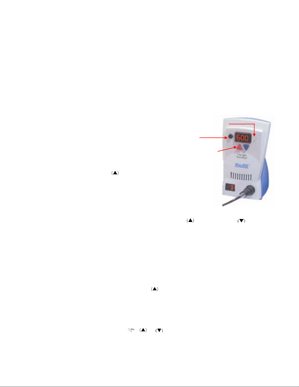
Program/
Menu Button
4. Once the tip has reached the desired heat level, the LED indicator will turn green and the
system is ready to use.
The HW 100 system comes standard with an Auto-Setback and Auto-Off Features. These are pre-
programmed for 30 minute SetBack and 30 minute Auto Off, which can be turned off by the switch on
the bottom of the unit. When Setback mode has been entered, the heat level will be adjusted to 3.5.
Setback can be exited by either thermally shocking the tip by placing it in a dampened sponge or by
simply switching the unit off for a brief moment. Auto Off can be reset by switching unit off then on.
TW 100 TempWise System
The TW 100 system is very easy to adjust and operate. The following instructions detail system
features and operation of the system. Information regarding changing of system options (e.g.,
Temperature Setback time, Auto Off) is contained in the "Programming Your System" portion of this
manual.
1. Ensure that the Set-Up procedure has been performed.
Verify the following:
a) Handpiece connection to the power source.
b) Proper tip installed in handpiece.
c) Power cord connection between an appropriate
AC supply and the power source.
2. Turn the Power Switch On ("I"). The display will begin
to increase as the TD 100 handpiece heats up.
3. Press the Scroll Up Key. The Set Temperature is now
displayed, immediately perform step 4.
NOTE: If a Password has been previously programmed into the
system, "EP" will be appear on the LED Display at this point.
When this message appears, the operator must enter the
correct Password before adjusting the temperature.
4. Adjust the temperature by pressing and holding Scroll Up Key or Scroll Down key.
Observe the display as the Set Temperature increases first in increments of 5°, then in
increments of 10°. When the desired temperature is reached, release the key.
NOTE: The Set Temperature can only be within the set temperature limits. If the lower limit
is reached, the display will read off. If the upper limit has been reached, the display
will read “HiL”. Temperature limits can be adjusted in the programming menu. See
“Programming Your System” section.
5. Observe the Digital Readout as the temperature reaches and stabilizes at the Set Tip
Temperature.
6. The system can be manually forced into Temperature Setback by pressing and holding
the Scroll Down (t) Key and the Scroll Up Key.
7. When the display begins to blink, the system is in Temperature Setback mode and will
reduce the set temperature to 177°C (350°F). NOTE: If Auto Off has been enabled in
the programming menu, the system will enter Auto Off (temperature Off and LED Display
flashing "Off") after the preset time of handpiece inactivity. Auto Off can be exited by
pressing any key.
8. To exit Temperature Setback mode, perform any one of the following:
a) Press and release a Key ( ,or ). This is the preferred method.
b) Wipe the hot handpiece tip on a wet sponge to thermally load the tip.
c) Turn the Power Switch Off ("0") and then back on ("I").
LED
Indicator
Scroll Up/Down
Buttons

©2004 PACE Inc., Annapolis Junction, Maryland
All Rights Reserved Page 9 of 17
9. The system is now in normal operation. Observe the LED Display as the tip temperature
reaches and stabilizes at the Set Temperature. Allow time for the temperature to
stabilize at the Set Temperature before using.
NOTE: Read the “Programming Your System” sections of this manual to utilize the full
capabilities of the system.
LED Display, Normal Operation
The LED Display provides a 3-digit display of temperature information. The LED Display will show:
1. A display of "888" on initial power up to ensure that all LEDs on the display are
working.
2. A display of the software version of the installed microprocessor (e.g., "1-7") for 1
second on initial power up after the "888" is displayed.
3. Actual tip temperature of the connected handpiece during normal operation. The tip
temperature displayed will flash when the system is in Temperature Setback.
4. The displayed temperature will decrease and stabilize at 177°C (350°F) when the
system is in Temperature Setback.
5. "OFF" when the Set Tip Temperature has been set to Off (below minimum set tip
temperature). Refer to the "Programming Your System" portion of this manual.
6. "OFF" plus the LED Display will be flashing when the unit has entered Auto Off.
Refer to the "Programming Your System" section of this manual.
7. Error messages ("OSE" or “OCE”) if a system fault is detected. Refer to the
"Corrective Maintenance" portion of this manual.
LED Display, Temperature Adjust Mode
The LED Display will show the following when adjusting the desired Set Tip Temperature.
1. The Set Tip Temperature.
2. "HiL" (High Temperature Limit) when adjusting the set tip temperature and the
maximum allowable temperature is exceeded. Refer to the "Programming Your
System" portion of this manual.
3. "OFF" (Low Temperature Limit) when adjusting the set tip temperature and the
minimum allowable temperature is exceeded. Refer to the "Programming Your
System" section of this manual.
3. "EP" will be displayed if a Set Tip Temperature adjustment is attempted and a
Password has been stored in system memory. As the Password is entered, the
display will change to the Set Tip Temperature if the entered Password matches the
stored Password.
5. "no" will be displayed if the entered password does not match the stored Password.
Temperature Setback Mode
To preserve tip life and save energy, the TW 100 system can be programmed to automatically set back its
Tip Temperature to 177°C (350°F) after a selected period of handpiece inactivity. The LED Display will
blink “177” or “350” depending on the selected temperature scale. As received from the factory, this
feature is enabled. Refer to number 9 in the “Programming Your System” section of this manual to
disable or adjust the time-out period of this feature. The operator can also force the system into
Temperature Setback.
Activating Temperature Setback: There are two ways to activate the Temperature Setback feature.
1. AUTOMATIC ACTIVATION: The system can be programmed so that this feature will
automatically activate after a pre-selected period (10-90 minutes) of handpiece inactivity.
See the “Programming Your System” section for details on programming this feature.

©2004 PACE Inc., Annapolis Junction, Maryland
All Rights Reserved Page 10 of 17
2. MANUAL ACTIVATION: The operator can manually force the system into Temperature
Setback by performing the following procedure.
a. Press and hold the Scroll Down Key and the Scroll Up Key.
b. Release both keys.
Exiting Temperature Setback: Listed below are 3 ways to exit Temperature Setback.
1. Press and release any key on the front panel (( ), or ). This is the preferred
method.
2. Wipe the hot handpiece tip on a wet sponge to thermally load the tip.
3. Turn the Power Switch “OFF” (“0”) and then back “ON” (“l”).
Set Tip Temperature values will be restored. For optimum performance, do not attempt to use the
attached handpiece until the Set Tip Temperature is achieved and the LED indicator is green.
Auto Off Safety System Mode
When enabled, the Auto Off safety system of the TW 100 system turns off the power to the handpiece 10-
90 minutes after entering Temperature Setback. When the system has entered Temperature Setback, an
Auto Off timer within the system circuitry will start running if Auto Off is turned on. Refer to number 10 in
the Programming Menu. When Auto Off has activated, the LED Display will blink “OFF”.
1. If any key is pressed during the selected time out period, the Auto Off timer is reset. The
system will return to normal operation.
2. At the end of the time out period, the system will enter Auto Off. Power is turned off to the
heater and the LED Display will show a flashing “OFF ” and the LED indicator will turn red.
Exiting Auto Off: Auto Off can be exited; returning to normal operation by:
1. Pressing and releasing any key on the front panel. ( ,or ), or
2. By turning the Power Switch OFF (“0”) and then back ON (“l”).
Using the TW 100 Calibration Feature
The new TW 100 systems feature an all-new calibration procedure. The system is calibrated so the
display matches the measured tip temperature using your own testing method. This new PACE feature
allows any type of temperature verification device to be utilized to complete the simple procedure.
Calibration can be completed, as often or as little as you like, in order to meet your own internal
specifications.
The steps for the procedure are:
1. Remove any offset from the system by disconnecting the handpiece from the system; the
LED should go to amber.
2. Set the TW 100 to 700°.
3. Record the actual temperature of the tip from your temperature verification device.
4. Place the TW 100 into the Calibration mode. This can be achieved by starting with the
system power switch in the off position. Press and hold the Program key and the UP key
while turning the system on. Release both keys when the display reads “1-7”, once released
the display will read “tIP.” Please note that if the system has already been calibrated that the
display will read “CSO” at this time. To clear this, simply momentarily remove the handpiece
from the system.
5. Use the UP
and DOWN keys to enter the temperature that you recorded by the
temperature verification device.
6. Press the PROGRAM key to exit. Upon exiting, LED will illuminate green.
NOTE: The system will display “CSO” (Clear System Offset) if an offset exists within the system.

©2004 PACE Inc., Annapolis Junction, Maryland
All Rights Reserved Page 11 of 17
The system will prompt the user to calibrate under specific conditions, for example, when the handpiece
has been removed. The system indicates whether calibration is required or not through the color of the
LED Indicator Light. When the LED Indicator is Green, the system is calibrated and ready for use, when it
is Amber, the system may need to be calibrated, and when it is Red, the system should be calibrated.
The following chart explains the function of the LED Indicator Light.
LED Indicator
Activity
Power On Amber
Calibration Complete Green
Tip Cartridge
Removed Red
Heater Open Sensor Red
System In SetBack Amber or Green*
System in Auto-Off Amber or Green*
System reactivated
after Auto-Off Amber or Green*
*The LED will be Amber or Green depending on the color when it entered Setback, or Auto Off.
NOTE: Before calibration is attempted, the system should be allowed to reach set temperature.
After turning on the system or changing tip cartridges, wait for at least 15 seconds before
calibrating.
Programming Your System
The menu driven LED Display of the TW 100 system allows you to easily customize your system. By
accessing the programming menu, you can:
• Enter, remove or change a Password.
• Set the Default Temperature scale to °F or °C as desired.
• Change the Upper and Lower Temperature limits.
• Enable or disable the Temperature Setback feature and adjust the time-out period.
• Enable or disable the Auto Off feature and adjust the time-out period.
• Enable or disable the Calibration mode.
The following instructions should be performed to familiarize the operator with the system.
Entering the Programming Menu
1. Place Power Switch in the “OFF” (“0”) position.
2. Press and hold the Program Key ( ) while turning on the Power
Switch (“I” position).
Password
3. The LED Display will display the version of the microprocessor and change to read “P--”
or "EP".
4. If the display reads "EP", a Password has been stored in system memory. Enter the 3
digit Password (using the scroll up/down keys). If the Password entered is incorrect, "no"
appears on the display and the system then returns to normal operation. If this occurs,
repeat steps 1 through 5 and enter the correct Password.
5. The LED Display reads "P--". Choose one of the following options:
a) Press the Program Key ( ) to keep the currently stored Password (including no
Password).
b) Press and release the Scroll Up or Scroll Down Key to enter a new password.

©2004 PACE Inc., Annapolis Junction, Maryland
All Rights Reserved Page 12 of 17
c) Set the display to “000” for no password.
Temperature Scale
6. The LED Display now shows the stored default Temperature Scale (°C or °F
temperature shown on LED Display). Choose one of the following:
a) Press the Program Key ( ) to keep the stored default Temperature
Scale.
b) Press and release the Scroll Up Key to change the default Temperature Scale.
Press and release the Program Key.
Temperature Limits
7. The LED Display now shows the stored default High ("Hi") Temperature Limit
with the display alternating to show "Hi" and the stored limit. Choose one of
the following:
a) Press and release the Program Key ( ) to keep the stored High
Temperature Limit.
b) Press and release the Scroll Up Key to increase the stored High Temperature
Limit (up to 454°C, (850°F)). Press and release the Program Key to proceed to the
next step.
c) Press and release the Scroll Down Key to decrease the stored High Temperature
Limit. Press and release the Program Key to proceed to the next step.
8. The LED Display now shows the stored default Low ("Lo") Temperature Limit
with the display alternating to show "Lo" and the stored limit. Choose one of
the following:
a) Press and release the Program Key ( ) to keep the stored Low
Temperature Limit (260°C, 500°F).
b) Press and release the Scroll Up Key to increase the stored Low Temperature
Limit. Press and release the Program Key to proceed to the next step.
c) Press and release the Scroll Down Key to decrease the stored Low Temperature
Limit. Press and release the Program Key to proceed to the next step.
Temperature Setback
9. The LED Display now shows the stored Temperature Setback time as "S-X"
(x=0 thru 9). Time is shown as tens of minutes (e.g., "S-3" equals 30
minutes). A display of "S- 0" indicates that Setback is disabled. Choose one
of the following:
a) Press and release the Program Key ( ) to keep the currently stored Temperature
Setback time.
b) Press and release the Scroll Up Key to enable and/or increase the stored
Temperature Setback time. Press and release the Program Key to proceed to the
next step.
c) Press and release the Scroll Down Key to decrease or disable the stored
Temperature Setback time. Press and release the Program Key to proceed to the
next step.
Auto Off

©2004 PACE Inc., Annapolis Junction, Maryland
All Rights Reserved Page 13 of 17
10. The LED Display now shows the stored Auto Off time as "AOx" (x=0 thru 9).
Time is shown as tens of minutes (e.g., "AO3" equals 30 minutes). A
display of "AO0" indicates that Auto Off is disabled. Choose one of the
following:
a) Press and release the Program Key ( ) to keep the currently stored Auto Off
time.
b) Press and release the Scroll Up Key to enable and/or increase the Auto Off.
Press and release the Program Key to proceed to the next step.
d) Press and release the Scroll Down Key to decrease or disable the stored Auto
Off time. Press and release the Program Key to proceed to the next step.
Exiting the Programming Menu
12. The LED Display now reads "End". The Set-Up Mode procedure is now complete.
Choose one of the following steps:
a) Press and release the Scroll Up Key to exit Set-Up Mode and
return to normal operation.
b) Press and release the Scroll Down Key to return to the start of
the Set-Up Mode procedure. Go back to step 4.
Factory Settings
TW 100 systems come equipped with a number of features, which may be adjusted as desired by the
user. Listed below are the features and factory settings of each. To change and/or learn about any
of these features, refer to the applicable part of the “Programming Your System” section of this
manual.
Feature Factory Setting
Password None Entered
°F for 115 VAC SystemsDefault Temperature Scale (°C/°F) °C for 230 VAC Systems
“HI” (Upper) Temperature Limit 454 °C (850 °F)
“LO” (Lower)Temperature Limit 260 °C (500 °F)
Set Temperature “OFF”
Temperature Setback Enabled, 30 minutes
Auto Off Enabled, 60 minutes
Factory Settings

©2004 PACE Inc., Annapolis Junction, Maryland
All Rights Reserved Page 14 of 17
Corrective Maintenance
LED Display Message Codes
Listed below are message codes, which, may be shown on the LED Display if a mistake is made by
the operator (e.g., wrong Password entry) or if the system has malfunctioned.
LED Display Message Description
The incorrect password has been entered. The displayed
message will time out after 6 seconds and revert to normal
operation. Enter the correct password.
No handpiece is connected to the power receptacle. Connect
handpiece.
The handpiece heater assembly sensor is open. Tip cartridge
may not be fully seated or heater has failed. Reinstall or replace
tip cartridge
Calibration error. Indicates Calibration did not complete properly.
LED Display Message Codes
Handpieces
Please refer to the respective handpiece manual for the maintenance procedures.
Handpiece/
System
TW/HW
MTS
PS 90 x
SX 70/80 x
TT 65 x
TP 65 x
TJ 70/80 x
TD 100 x x
MT 100 x x
The above table illustrates the handpieces that can be utilized with the respective system.
Power Source
Refer to the table below. Most malfunctions are simple and easy to correct.
Symptom Probable Cause Solution
No power to
system Blown Fuse Replace the fuse (located in the AC Receptacle
Fuse Holder) with one of the same rated value.
Defective Heater Change Tip Cartridge. Refer to the TD-100/MT-
100 Handpiece manual for the maintenance
procedures.
Handpiece will
not heat
Power Source
Malfunction Contact PACE
Power Source Corrective Maintenance
CE
E

©2004 PACE Inc., Annapolis Junction, Maryland
All Rights Reserved Page 15 of 17
Packing Contents
Description HW 100 System TW 100 System
Power Supply HW 100 TW 100
Handpiece TD-100
(6010-0132-P1) TD-100
(6010-0132-P1)
Tip & Tool Stand 6019-0068-P1 6019-0068-P1
Power Module Kit
Contains 6.5, 7, & 7.5 Modules 1207-0365-P3 N/A
Hot Grip Removal Pad 1100-0307-P1 1100-0307-P1
CD Manual CD5050-0459 CD5050-0459
Replacement Power Modules
Description PACE Part Number
Power Modules
5/Green 1207-0362-01-P1
5.5/Blue 1207-0362-02-P1
6/Orange 1207-0362-03-P-1
6.5/Gold 1207-0362-04-P1
7/Red 1207-0362-05-P1
7.5/Purple 1207-0362-06-P1
8/Black 1207-0362-07-P1
8.5/Silver 1207-0362-08-P1
Service Please contact PACE or your local distributor for service and repair.

©2004 PACE Inc., Annapolis Junction, Maryland
All Rights Reserved Page 16 of 17
PACE WORLDWIDE LIMITED WARRANTY STATEMENT
Limited Warranty
Seller warrants to the first user that products manufactured by it and supplied hereunder are free of
defects in materials and workmanship for a period of three (3) years from the date of receipt by such user.
This Warranty as applied to blowers, motor pumps, x-ray tubes, lenses, optical/lighting probes and
cameras is limited to a period of one (1) year. Monitors, computers and other brand equipment supplied
but not manufactured by PACE are covered under their respective manufacturer’s warranty in lieu of this
Warranty.
This warranty does not cover wear and tear under normal use, repair or replacement required as a result
of misuse, improper application, mishandling or improper storage. Consumable items such as tips,
heaters, filters, etc. which wear out under normal use are excluded. Failure to perform recommended
routine maintenance, alterations or repairs made other than in accordance with Seller’s directions, or
removal or alteration of identification markings in any way will void this warranty. This warranty is
available only to the first user, but the exclusions and limitations herein apply to all persons and entities.
SELLER MAKES NO OTHER WARRANTY, EXPRESS OR IMPLIED, AND MAKES NO WARRANTY OF
MERCHANTABILITY OR FITNESS FOR A PARTICULAR PURPOSE.
Seller will, at its option, repair or replace any defective products at its facility or other location approved by
it at no charge to user, or provide parts without charge for installation by the user in the field at user’s
expense and risk. User will be responsible for all costs of shipping equipment to Seller or other location
for warranty service.
EXCEPT FOR THE REMEDY ABOVE DESCRIBED, UNLESS OTHERWISE REQUIRED BY
APPLICABLE LAW, SELLER WILL HAVE NO OTHER OBLIGATION WITH REGARD TO ANY BREACH
OF WARRANTY OR OTHER CLAIM WITH RESPECT TO THE PRODUCTS, OR LIABILITY FOR ANY
DIRECT, INDIRECT, CONSEQUENTIAL, OR INCIDENTAL LOSS OR DAMAGE CAUSED BY OR
OCCURRING IN CONNECTION WITH ANY OF THE PRODUCTS.
Warranty service may be obtained by contacting the appropriate PACE Company or local Authorized
PACE distributor as set forth below to determine if return of any item is required, or if repairs can be made
by the user in the field. Any warranty or other claim with respect to the products must be made with
sufficient evidence of purchase and date of receipt, otherwise user’s rights under this warranty shall be
deemed waived.
For PACE USA Customers:
PACE, INCORPORATED
9030 Junction Drive
Annapolis Junction, Maryland 20701
Tel. 301-317-3588
FAX: 301-498-3252
For PACE EUROPE Customers:
PACE EUROPE LIMITED
Sherbourne House, Sherbourne Drive,
Tilbrook, Milton Keynes
MK7 8HX
United Kingdom
Tel. (44) 1908 277666
WARRANTY SERVICE FAX: (44) 1908 277 777
All other Customers:
Local Authorized PACE Distributor

©2004 PACE Inc., Annapolis Junction, Maryland
All Rights Reserved Page 17 of 17
Contact Information
PACE Incorporated retains the right to make changes to specifications contained herein at any time,
without notice. Contact your local authorized PACE Distributor or PACE Incorporated to obtain the latest
specifications.
The following are trademarks and/or service marks of PACE, Incorporated, MD, USA:
INSTACAL™, FUMEFLO™, HEATWISE™, PACEWORLDWIDE™, PERMAGROUND™,
POWERPORT™, POWERMODULE™, TEMPWISE™, TIP-BRITE™, AUTO-OFF™,and
TEKLINK™.
The following are registered trademarks and/or service marks of PACE Incorporated, Annapolis Junction
Maryland U.S.A.
ARM-EVAC®, FLO-D-SODR®, MINIWAVE®, PACE®, SENSATEMP®, SNAP-VAC®,
SODRTEK®, SODR-X-TRACTOR®, THERMOFLO®, THERMOJET®, THERMOTWEEZ®,
and VISIFILTER®, THERMO-DRIVE®, TOOLNET®.
PACE products meet or exceed all applicable military and civilian EOS/ESD, temperature stability and
other specifications including MIL STD 2000, ANSI/JSTD 001, IPC7711, and IPC A-610.
www.paceworldwide.com
PACE USA PACE Europe
9030 Junction Drive Sherbourne House
Annapolis Junction, MD 20701 Sherbourne Drive
USA Tilbrook, Milton Keynes
MK7 8HX
United Kingdom
Tel: (301) 490-9860 (44) 1908-277666
Fax: (301) 498-3252 (44) 1908-277777
Other manuals for HW 100 HeatWise
1
This manual suits for next models
5
Table of contents
Other Pace Soldering Gun manuals

Pace
Pace MicroBenchtop MBT-100 Troubleshooting guide

Pace
Pace ST 25 User manual

Pace
Pace SODRTEK ST 125 User manual

Pace
Pace ST 45 User manual

Pace
Pace MBT250 Manual

Pace
Pace SODRTEK ST 325 User manual

Pace
Pace WJS 100 User manual

Pace
Pace SX-100 User manual

Pace
Pace 5050-0552 User manual

Pace
Pace TD-100 User manual