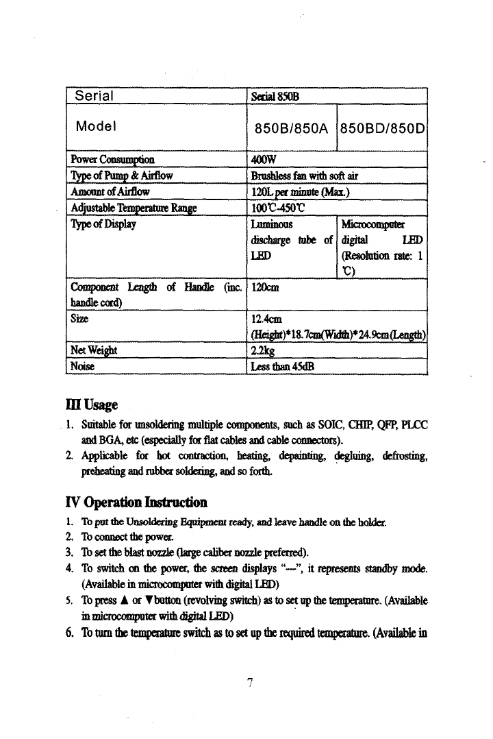
YIHUA 858 Series User manual

EJSeria1858
Brushless
Fan
with
Soft
Air
Unsoldering
Equipment
With
Hot
Air
for
SMD
-, 1M
i~
X6917
ii
U
1
,
fWc
,
Thank
you
for
choosing
this
type
of
Unsoldering
Equipment
with
HotAir.
The
product
is
designed
for
soldering
and
unsoldering
without
lead.
Please
read
the
User
Guide
thorough
ly
before
use,and
keep
it
in
a
safe
place
for
future
reference.

14
1.
1
,1
ffl
Q
Cpl
Ni
,
q
,
LED
~
T
,
T1
*,
f7~z$
Mf
r:
~iR
sul7,
-'
•
pJj~l,
i~1
Lf
JJU
3.
Fl
~
r
$$
{~
:
ryry ~~
,
i
71'7
~~T
'~K,
S
•
J\•,
nT~~x~
s~
•
q
t
r=1
~
%I
858
U
858/858+/858A
858D/858AD/858AD+
j)Jf
700W
~a~'J
JL
n
i
t
120
f/,
(
f)
t
il
l
100°C
-450°C
100°C-500°C
LED
Y
LEDt
(r}
1
°
C)
~fi
k
120cm
11,
R~
13.8cm(~)*10cmO*15cm(+~)
1.55kg
a
/J\f45dB
1

fi
r.
~1
850B
5
850B/850A
j
850BD/850D
T)j
4
I
400w
'J
PIJL
n
fit
r
C≥
120~-/~}
t(
*)
f
it
1
I
100°C
-450°C
$
LEDi~zfl
LED
S(
( )
1°C)
120cm
#JL
J
j
12.4cm(
)
*
18.7cm(
)
*24.9cm(J)
Jl
2.2kg
ij~
45dB
L.
ja
]
#
fop
:
S©IC.
CHIP.
QFP,
PLCC.
BGA
2
,
~
°
a.
#T
Fed
JF*,
,
l
pf#F
`d
I1
(LED
I
'~"
t~~T
!)
5.
1
„
A
„
Win
4
(1Er#
i
i~sf~
I
(LED1(
6
.
7
.
~q~, ~Im
/R
yG
fC
G
,
~ p
G
l~f17
1YJ~°

s,
sib
c
#L°
J
tiit~#
~,
1k
~f#iFtf
ii7J
n
,
T
1OO°
f~T "---"
ik
f '
o°C
f
7o°c,
R
IE
f'o°C
a
i
l
1
f
IE
Ifs)
#
f1
k~h'I
F,
gJLi,
a
#
1~1~#►f>~~3~~ii~ft'J~~i
7~₹1`#i'~f.~1C
~~'ft~l~~o
1.
%~
> #>
~
JJt
1
;
)t
"
V
"
1
°
C;
"A„
"Y
„
~~Ja~fu~3J
T
f
4ttI
,
a'W
~T
"---
"
n~If"t#1Lfik~-o
I
i
:
i
~A
A.
"---"
,
Tel
qi
i
f1OO°C,
B.
"S
-
E"
T
rt
f>lJi
!F
~p7
J
(
$
i~!
Wf
f
)
C.
"S—A"
r
f
~
1idJLii;
ip1~,
J
idJZ
3

ft
D.
sf~A$,
i1~f
50C,
*T31
L
r.#
id
1
un
1~
3
.
1
f
#
i$lf
iiL~~~
~
7O
4.
2'(1
cpFn,
#L°flA
#
#fiti
1*h,
L2n~zb
i
~i
7o
Ck(F
(i~Af
#fLk1F
)
11
~A&Jf
5
LI
6.
1
#
I11
,
iluf,
tJflJJ
fl
,
-
t:
.
#
z
1,
1
f1;
?.
#tA~,
#u~F
#i~Hhrpfl
o
4.
$
di
I
L
,
11q
fl
#
t
fl3fi.
5'
JL
1
h
#4
3fi
11•
~h
i~
,
?
iJ
f
4

s.
.
iJS
5"c
1f~i
#
i1ih
~
9.
#~F
1Hfl
liz
FrCl
t~$#~a
iI
.
1.
1
fl
:
u;t
,
3.
Lpl
?MI
1H#.
f~l~
fL
f~I
4
Component
handle
(
)
Heating
element
(
tM1)
Micapaper
( )
$7
5
Handle
cover
(
)

I
Feature
1.
Closed
circuit
Sensor,
m
ocomputer
zero-erossm8
soft
touch
temperature
control,
LED
visual
display,
high
power,
rapid
rise
of
temperature,
accurate
and
stable
temperature,
little
influence
of
air
outflow,
and
unsoldering
without
lead.
2.
Ac
astable
airflow,
large
and
soft
airflow
easy
adjustment
of
temperature,
suitable
for
multiple
usages.
3.
Hand
handle
with
sensor
switch,
the
system
will
turn
into
the
working
mode
while
the
handle
is
held;
and
the
system
will
standby
while
the
handle
is
pat
on
the
holder,
which
is
very
convenient
for
operation.
4.
Automatic
cooling
function
of
the
system
will
prolong
the
life
of
heating
element,
and
protect
the
hot
air
gun.
S.
Broshless
fan
with
bong
lifetime,
low
nose;
high
quality
beating
eknrnt
with
good
quality
beating
wine
and
double
efficiency
at
the
same
power
will
prolong
its
life
and
save
energy.
II
Specification
Serial
Serial
858
Model
858/858+/
858A
858D/858AD/
858AD+
Power
Consumption
700w
Type
of
Pump
&
Airflow
Brushless
fan
with
soft
air
Amount
of
Airflow
120L
per
minute
(Max.)
AdjustablelemperahueRange
100°C
-
450°C
100°C
-500°C
Type of
Display
Luminous
discharge
tube
of
LED
Microcomputer
dig!tAl
LED
(Resolution
rate:
1
C)
Component
Length
of
Handle
(inc.
handle
card)
120cm
Size
13.8cm
(lieiight}+lOcm(W'~h}'r15cm(Leugth)
1.55kg
Net
Weight
Nuise
Less
than
45dB
6

Serial
Serial
850B
Model
850B/850A
850BD/850D
Power
Cansum~ion
400W
Type
of
Pump
&
Airflow
Bnrsbless
fan
with
soft
air
Amount
of
Airflow
121N
per
minute
(Max.)
100O.450t
AdjastabkT~p..ratt.ieRange
Ty
pe
of
Display
Luminous
discharge
tube
of
LED
Mii
.0
owputct
digital
LED
(Resolution
rate:
1
G)
Component
Length
of
Handle
(mc.
handle
card)
12m
Site
12.4cm
(FIeig)nt)~18.7cm(Width)'249cm(Length)
Net
Weight
2.2kg
Noise
Less
than
45dB
II
I
Usage
1.
Suitable
for
isoldering
multiple
components,
such
as
SOIC,
CHIP,
QFP,
PLCC
and
BGA,
etc
(especially
for
flat
cables
and
cable
connectors).
2.
Applicable
fot
hot
contraction,
heating,
depainting,
degluing,
defrosting,
preheating
and
rubber
soldering,
and
so
forth.
IV
Operation
Instruction
1.
lb
put
the
Unsoldering
Bquiprnent
ready,
and
leave
handle
on
the
holder.
2.
l
connect
the
power.
3.
To
set
the
blast
nozzle
(large
caliber
nozzle
preferred).
4.
To
switch
on
the
power,
the
screen
displays
"—"
it
represents
standby
mode.
(Available
in
microcomputer
with
digital
L®)
5.
To
press
A
or
♦button
(revolving
switch)
as
to
set
up
the
temperature.
(Available
in
microcomputer
with
digital
LED)
6.
To
turn
the
temperature
switch
as
to
set
up
the
required
temperature.
(Available
in

luminous
discharge
tube
display
indication)
7.
To
hold
the
handle,
so
the
equipment
begins
to
beat.
To
adjust
the
re
volving
switch
of
airflow.
in
order
to
select
suitable
airflow,
and
begin
to
operate
normally
while
the
temperature
is
stable.
8.
To
pat
back
the
handle
on
the
holds
after
the
work;
meanwhile,
the
Unsoldering
Equipment
switch
from
heating
mode
to
cooling
heating
element
mode
automatically.
While
the
temperature
is
lower
than
100
C,
the
screen
displays
"—",
it
stands
far
switching
to
standby
mode,
and
after
the
temperature
of
heating
elemem
is
less
than
70'C,
the
equipment
is
on
standby
(If
th
erein
airflow
out,
it
means
the
itmpe
atore
is
higher
than
70t;
and
there
is
no
airflow
only
after
the
temperature
is
lower
than
70
C
).
9.
To
switch
off
the
power
and
unplug
if
there
is
no
operation
fora
long
period
of
time.
Attention:
Try
to
set
up
the
temperature
as
lower
as
possible
and
the
airflow
as
mach
as
peesible
as
to
keep
heating
dement
working
longer
and
protect
IC
chips.
V
Settrng
up
Temperatmre
I.
Unsoldering
Equipment
with
luminous
discharge
tube
display
indication
*
To
turn
the
temperature
control
switch
to
the
required
mark.
2.
Unsoldering
Equipment
with
microcomputer
digital
LID
visual
display:
*
To
press
A
or
Ybattoon
(revolving
switch),
dre
screen
displays
the
temperature
while
the
power
is
on.
*
To
press
A
once
(revolving
clockwise),
the
temperature
degree
is
added
it,
the
scree
displays
the
teaoperanue;
to
press
V
once
(revolving
anndockwdse),
the
temperature
degree
is
subtracted
it;
and
if
A
or
Ybutton
is
pressed
continuously,
the
temperature
will
8

increase
or
decrease
rapidly.
After
the
button
is
released,
the
screen
displays
set
tempaakue
for
two
seconds
and
then
displays
current
temperature
or
"—",
the
standby
mo
de.
Note:
Explanatlen
of
Symbols
A.
"---"
represents
the
temperature
is
lower
than
100G,
standby
mode,
and
the
handle
is
on
the
holder.
B.
"S
-B"
repots
there
is
problem
of
the
sensor,
so
the
heating
element
(mc.
heating
material
and
)
Mall
be
replaced.
C.
"S
-A"
represents
there
is
problem
of
th
e
memory,
so
the
memory
(it
can
save
the
set
temperature
far
100
years)
sbaf
be
replaced.
D.
The
temperatre
is
lower
than
SOG
and
no
raix
it
wlnle
it
is
woddag,
whkh
represents
there
is
problem
of
the
heating
element,
so
th
e
heating
element
(inc.
heating
material
and
)
shall
be
replaced.
Vl
Terms
Of
Use
1.
The
air
outlet
and
its
surrounding
area
maybe
very
hot.
Be
cautious
of
scald.
2.
The
treating
handle
shall
not
be
pat
on
the
working
table
or
otter
pla
a
except
its
holder.
3.
To
keep
the
air
outlet
anblocked.
4.
To
put
de
heating
handle
on
its
holder
after
the
work,
and
keep
it
cool
naturally
to
the
standby
mode,
th
en
switch
off
the
power.
5.
The
distance
between
the
air
outlet
and
the
object
shall
be
no
less
than
2mm.
6.
To
choose
suitable
blast
nozzle
in
accordance
with
working
requirements.
Different
blast
nozzles
may
have
different
temperatures.
VII
Replacement
of
feaUng
Element
1.
The
h
sting
element
shall
be
replaced
dining
its
cooling
condition.
2.
To
fasten
two
screws
fixed
on
the
handle
as
illustrated
3.
To
disassemble
the
component
of
the
handle,
and
then
take
out
the
handle cover
4.
Move
the
equipments
gently
and
screw
off
three
screws
used
for
fixing
the
tcadnal
board.
9

5.
To
turn
over
the
terminal
board
and
disconnect
the
connection
fr
om
it,
and
be
careful
of
the
connection
position.
6.
To
take
out
the
hearing
element
and
mica
paper
coving
it
fr
om
the
steel
tube,
and
not
to
break
the
ground
connection.
7.
To
wrap
the
new
heating
element
with
mica
paper,
and
insert
it
into
the
steel
tube,
and
be
careful
of
correct
installation.
8.
To
connect
the
connection
in
accordance
with
its
former
position.
9.
To
install
the
handle.
Attention:
1.
Do
not
break
the
ground
connection
on
the
steel
tube
during the
replacement
of
heating
element.
2.
Do
not
break
the
connection
on
the
Unsoldering
Equipment
during
the
replacement
of
heating
element.
3.
The
link
assembly
on
the
handle
cover
shall
be
put
in
side
of
fixing
hole
on
the
steel
tube
during
the
installation
of
handle
components.
Component
handle
(
l
ll
)
Heating
element
(
##~4r
)
Mica
paper
(
ft
)
10
Handle
cover
($1
)

y
~Pq~7~~PP'
1
Aq~
Y
7
j
nn
1 •
F,
%Q
J
~Jp~
ALL
J
HEJ
2.
#<AJT
31
J~'c
d~i~h
$1C~K
(
A.
J
)J~
3c~~r
L
Z~C
TI
u~iI
H1t
~
B.
fW~
~pq~7~nE
Y7
/X
~iTii~N'~A715 U1i~~
This manual suits for next models
5
Table of contents
Other YIHUA Soldering Gun manuals