2
ITALIANO
1
2
3
4
5
6
7
8
9
10
11
12
13
14
15
16
17
18
19
20
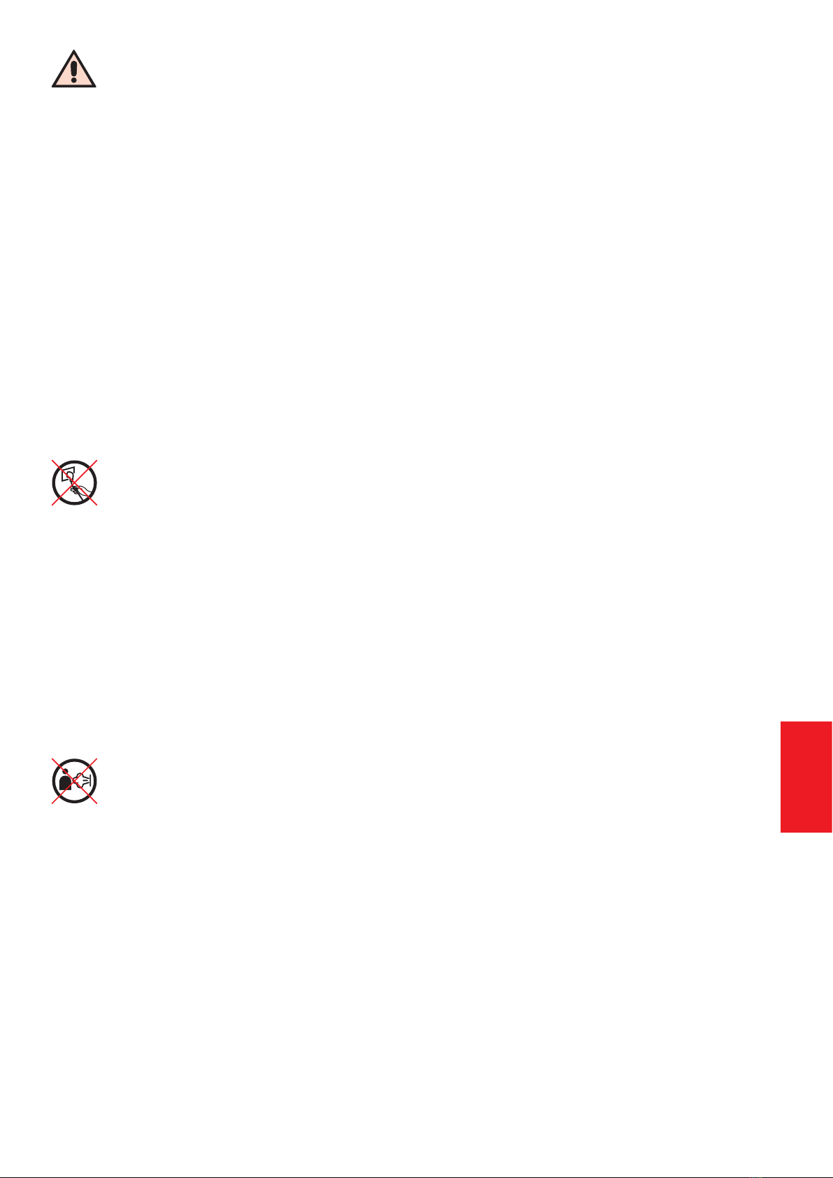
PRENDERE FAMILIARITÀ CON L’APPARECCHIO, LE SUE PARTI, I COMANDI
SERBATOIO DI RECUPERO
È il serbatoio nel quale viene recuperato lo sporco. È dotato di
sensori che consentono di rilevare il livello dell’acqua. I sensori
devono essere mantenuti puliti per una corretta rilevazione del
livello dell’acqua. Deve essere inserita in esso una certa quan-
tità d’acqua no ai livelli indicati, in entrambi i settori del serba-
toio. Se si procede alla pulizia con vapore o alla aspirazione di
liquidi, è sufciente immettere acqua nel solo settore esterno.
Senza acqua nel settore esterno l’aspirazione non può essere
attivata.
CESTELLO DI FILTRAGGIO
Posto sopra al serbatoio, garantisce l’azione di ltraggio. È do-
tato di sensori che consentono di rilevare il livello dell’acqua e
di un ltro (F1) che regola il usso d’aria. Il ltro va mantenuto
sempre pulito ed asciutto.
COPERCHIO SERBATOIO
Si apre sganciando la leva (N) e premendo leggermente sul
pulsante (P), permette di accedere al cestello e al serbatoio di
recupero per inserire l’acqua di ltraggio ed effettuare le nor-
mali operazioni di pulizia. Per chiudere il coperchio, ruotarlo
no a farlo agganciare e poi riportare la leva verso il manico.
Quando è chiuso il manico consente di trasportare agevolmen-
te l’apparecchio.
PRESA ASPIRAZIONE-VAPORE
Protetta da uno sportellino che si apre agendo sull’apposito
incavo, la presa permette di collegare alla unità i dispositivi di
pulizia e stiratura. È dotata di contatti elettrici, una connessione
vapore, un condotto aspirazione.
COPERCHIO FILTRO LATERALE
Il ltro laterale in materiale antistatico, è il dispositivo attraver-
so il quale l’aria, già ltrata dall’acqua, viene espulsa nell’am-
biente. Occorre vericare periodicamente lo stato del ltro e
sostituirlo all’occorrenza. Un ltro sporco o danneggiato non
garantisce una corretta pulizia e può diminuire la potenza aspi-
rante dell’apparecchio. Per accedere al ltro basta aprire lo
sportellino laterale nel quale è collocato.
COPERCHIO FILTRO INFERIORE
Il ltro inferiore, posto in una sede sotto all’apparecchio, serve
ad evitare che polveri in sospensione nell’ambiente, niscano
nei condotti di raffreddamento del motore. Questo ltro non
agisce nel circuito della pulizia. Occorre periodicamente ve-
ricarne lo stato e, all’occorrenza, pulirlo. Può essere lavato
con acqua. Asciugare prima di rimettere nella sua sede. Per
accedere al ltro basta ruotare il coperchio nel senso indicato
dalle frecce. Tenendo pulito il ltro inferiore, si migliorano le pre-
stazioni del motore e si prevengono malfunzionamenti.
CASSETTO PORTA CAVO ALIMENTAZIONE
Posto sotto al serbatoio di recupero, si apre tirando dalla ap-
posita ansa, serve a riporre il cavo di alimentazione dopo l’uso.
La stessa ansa consente di chiudere il cassetto con il cavo di
alimentazione estratto.
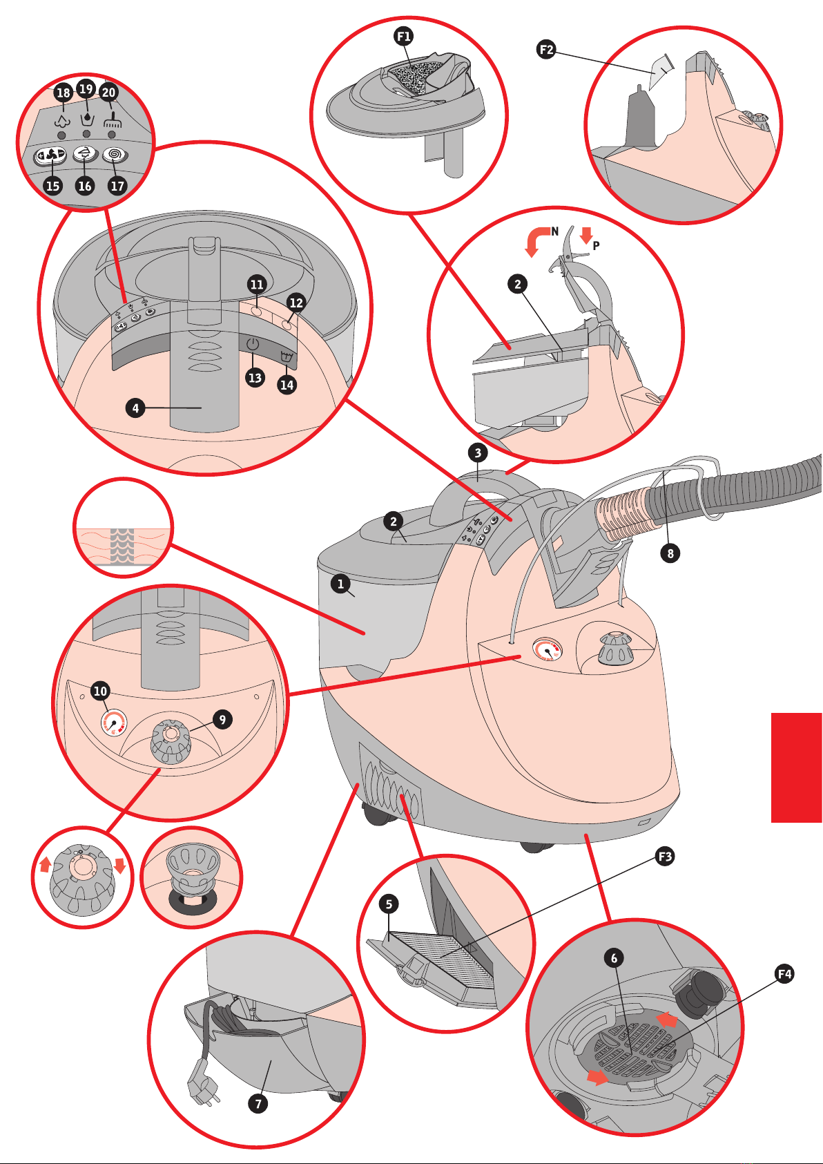
ANTENNA
È costituita da un lo di acciaio inossidabile ed è ssata all’ap-
parecchio tramite due fori. La sua funzione è quella di soppor-
tare parte del peso del essibile, alleggerendo il lavoro durante
le operazioni di pulizia. Porre il essibile sopra la apposita sede
della antenna come in gura. L’antenna può essere rimossa
per riporre l’apparecchio.
TAPPO IMBUTO
Il tappo per il riempimento della riserva di acqua può essere
aperto mentre la caldaia è in pressione. Per aprire tirare dalla
ghiera. Il tappo funziona anche come imbuto per l’immissione
dell’acqua. Girare la ghiera dalla posizione ● alla posizione ○.
Far scorrere il cannocchiale come in gura. Inserire il tappo
capovolto nell’imbocco del serbatoio. Prima di rimettere il tappo
a chiusura del serbatoio, mettere il cannocchiale in posizione
chiuso e girare la ghiera alla posizione originaria ●.
MANOMETRO
E’ un dispositivo che indica lo stato della pressione della cal-
daia. Il suo funzionamento è indipendente dalla alimentazione
elettrica della macchina.
INTERRUTTORE ACCENSIONE GENERALE
INTERRUTTORE CALDAIA
SPIA ACCENSIONE GENERALE
SPIA ACCENSIONE CALDAIA
TASTO REGOLAZIONE VELOCITA’ MOTORE
Spingendo il tasto nella zona + si attiva il motore di aspirazione
e si aumenta la potenza di aspirazione. Spingendo il tasto nella
zona - diminuisce la potenza del motore. Tenendo premuto in
una qualsiasi zona per alcuni secondi il motore si spegne. La
potenza della aspirazione è indicata da un segnalatore lumi-
noso rosso posto sotto al simbolo: intermittenza lenta = bassa
potenza, sempre acceso = massima potenza.
TASTO FERRO
Premendo il tasto ferro si ha la possibilità di utilizzare il ferro da
stiro (optional). Si accende il relativo indicatore luminoso posto
sotto al tasto. Quando è attivo il tasto ferro non è possibile azio-
nare il motore. Il ferro da stiro collegato non viene alimentato se
non è attivo il tasto ferro.
TASTO PURIFICATORE
Premendo il tasto puricatore il motore si aziona alla velocità
idonea ad effettuare la puricazione dell’aria. L’indicatore posto
sotto al tasto si accende. Premere di nuovo il tasto per fermare
il motore. Il tasto puricatore non è attivabile se la caldaia (in-
terruttore 12) è accesa.
SEGNALATORE VAPORE PRONTO
Si accende quando la caldaia ha raggiunto la pressione di
esercizio. Attendere che il segnalatore si accenda prima di co-
minciare ad utilizzare il vapore. Successivamente trascurare lo
stato della spia.
SEGNALATORE VUOTO
Quando si accende ssa e contemporaneamente interviene
il segnalatore acustico (buzzer) manca acqua nel serbatoio
freddo. Immettere acqua come indicato al passo 1. Quando
si accende ssa senza segnalazione acustica, manca acqua
nel serbatoio di recupero (1). Immettere acqua nel serbatoio
di recupero come indicato al passo 2. Quando si accende ad
intermittenza assieme al segnalatore della velocità del motore
(15) il serbatoio di recupero è pieno e deve essere svuotato.
SEGNALATORE ELETTROSPAZZOLA ABILITATA
Indica che è abilitato l’uso della elettrospazzola (optional).
L’indicatore si spegne quando si accende la caldaia.
>Corpo Macchina