Unitrol 8400 User manual

PROCESS WATER CHILLER
8400, 8401, 8406, 8450, 8451, 8456
UNITROL ELECTRONICS, INC.
702 LANDWEHR ROAD
NORTHBROOK, IL 60062
847-480-0115
info@unitrol-electronics.com


WARRANTY
PARTS: Unitrol warrants this chiller to be free of defects in materials that
effect operation, for a period of one year from date of shipment from
factory, if said equipment has not been altered or abused by customer
and is being used for the purpose that the equipment was designed for.
Parts will be shipped, FOB Northbrook, Illinois. Defective parts will be
returned to Unitrol at customer’s expense when so requested by Unitrol.
LABOR: Necessary warranty labor is covered for a period of 90 days
from the date of shipment from factory, if said equipment has not been
altered or abused by customer and is being used for the purpose that
the equipment was designed for. Parts will be replaced or repaired, at
manufacturer’s option on any parts found to be defective. Unitrol shall
not, without its prior written approval, be liable for any costs involved in
field repairs. Transportation of equipment to or returning from Unitrol
shall be at customer’s expense.
Alternately, Unitrol may elect to send a local refrigeration contractor to
do warranty service. In this case, Unitrol will pay contractor directly.
To be covered by this warranty, please follow the following procedure:
1. Contact the Unitrol service department at 847-480-0115 to discuss
the problem you are having with this chiller.
2. If Unitrol concurs that this is a warranty issue, and the chiller is
more than 90 days from date of factory shipment, a Unitrol
representative will either arrange to have a replacement part
shipped, or authorize a locally purchased replacement at a pre-
agreed price that will be reimbursed by Unitrol.
3. If Unitrol concurs that this is a warranty issue, and the chiller is
less than 90 days from date of factory shipment, a Unitrol
representative will have a factory approved service technician
dispatched to make repairs under the above terms. Alternately, the
Unitrol representative will direct that the chiller be returned to the
factory for repairs.
No other warranty, either written or implied, shall cover this equipment,
and Unitrol shall not be liable for any damage caused to other equipment
or personnel due to failure of this product. Unitrol reserves the right to
change specifications at any time.


UNITROL PROCESS WATER CHILLER
Thank you for purchasing this Unitrol process water chiller. It was manufactured
with pride in our Northbrook, Illinois factory. Unitrol also manufactures the Unitrol
line of RESISTANCE WELDING CONTROLS. This line includes controls that
include safety systems to protect the welding machine operator, as well as quality
control features that allow you to produce a large volume of weldments that will
match the highest quality requirements.
This Unitrol water chiller has been designed to operate under the most severe
industrial conditions. Please observe the installation instructions to be sure that
this chiller will provide years of superior service.
MODEL NUMBER:
SERIAL NUMBER:
DATE OF MANUFACTURE:
REFRIGERANT: R407C
OPTIONS:
CHILLER MODEL
LINE
VOLTAGE
AND PHASE
WATER PUMP
8400
480/3
3 HP, 80GPM @35PSI
8401
230/3
3 HP, 80GPM @35PSI
8406
575/3
3 HP, 80GPM @35PSI
8450
480/3
5HP, 180GPM @35PSI
8451
230/3
5HP, 180GPM @35PSI
8456
575/3
5 HP, 180GPM @35PSI
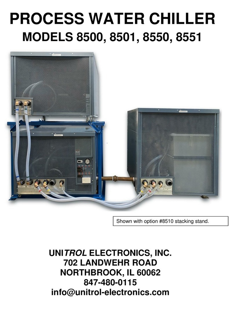
This model chiller is supplied in two MODULES:
RIGHT MODULE = First stage compressor with water pump
and control panel
LEFT MODULE = Second stage compressor, water tank.
Field connection of electrical and water circuits for the two
modules is required. All wires and hosing is provided for this
interconnection.

NOTES

TABLE OF CONTENTS
Installation……………………………………….………1
Wire and Fuse size chart…………………….………..4
Inter-module Wiring…………………………………….5
Plumbing
Pipe insulation…………………………….……......6
Pipe Size Chart……………………………….…….6
Makeup Water………………….…………………..6
Installing Y-Strainer…………….…………………..7
Interconnecting Hose Connection………………...8
Initial Startup………………………….………………....9
Setting Temperature Controller…….……….……12
Temperature Control Operation……………12
Bypassing Chiller During Service………….13
Control Panel……………………………………….14
TROUBLE SHOOTING
Diagnostic Lights
Low Water Flow…...……………………………….15
Low Freon Fault…………………………………....16
High Freon Fault………………….……………..…16
Low Water Level Fault…………………………….17
PREVENTIVE MAINTENANCE……………….….……18
DOCUMENTS:
Plumbing Installation Drawing……………………….….19
Schematic Diagram, 460/3 chillers..……………………20
Optional Dew Point controller schematic………………21
Internal Plumbing Diagram………………………………22
Optional Fault Monitor system…………………………..23

MAINTENANCE RECORD
DATE
PROBLEM
RESOLUTION

INSTALLATION
UNITROL MODEL 8400, 8401, 8406, 8450, 8451, 8456
1
1. Carefully uncrate both modules and inspect for external damage. If any damage is seen, do
not continue until a representative of the freight company views the damage, and a claim to
the freight company has been filed.
2. Remove the right side panel of the LEFT MODULE (with water tank).
3. Remove the front screens from both modules.
4. Install one of the ½” X 12” brass pipes into the water
pump on the RIGHT MODULE (with control panel).
5. Install the second ½” X 12” brass pipe into the
black bulkhead fitting on the water tank in the
LEFT MODULE.
THIS CHILLER IS DESIGNED FOR INSIDE INSTALLATION.
ONLY CHILLERS PURCHASED WITH THE –OS (OUTSIDE)
KIT CAN BE INSTALLED OUTSIDE IN AREAS WHERE
THE AIR TEMPERATURE CAN FALL BELOW 45ºF, AND
SUCH INSTALLATION WILL VOID THE WARRANTY.
USE A WRENCH ON THE BLACK BULKHEAD FITTING MOUNTED
ON THE WATER TANK WALL TO KEEP IT FROM ROTATING WHEN
INSTALLING THE BRASS PIPE.

INSTALLATION
UNITROL MODEL 8400, 8401, 8406, 8450, 8451, 8456
2
Install the chillers in a location that will keep the air intake (back of chiller with air filter) and air
exhaust (front of chiller with expanded metal plate) at least 36” from the nearest wall. This is
required to allow maximum air movement over the condenser coil.
CAREFULLY push the two modules together so that the 2” brass union mates, and tighten. If
desired, bolt the modules in place using the four mounting pads at the end of the round legs
Remove the water tank cover and untie the water float. Leave the water tank cover off for now.
RIGHT MODULE: Run a flexible cable from the service hole below the
ON/OFF switch to a local fused disconnect. The fused disconnect
should be no more than 36” from the point of entry to the chiller.
Connect the three power wires to terminal block marked L1, L2, and L3
inside the control compartment.
The order of wire connection is not important now and will be checked
later. Check the nameplate to be sure that the line voltage
matches the incoming service.
6. GROUNDING: Be sure that there is a fourth ground wire inside
this conduit. Connect this wire to the ground lug terminal on the
base pan just below this wiring compartment. This ground lug
has a green sign located next to it. This wire should be sized to
handle at least 50% of the total of both module amperage.
FAILURE TO ALLOW MINIMUM WALL CLEARANCE
WILL RESULT IN HIGH FREON TEMPERATURES AND
WILL VOID WARRANTY.
POWER ENTRY POINT
A SEPARATE LINE VOLTAGE SERVICE WILL BE CONNECTED TO EACH MODULE:
RIGHT MODULE
CONNECT GROUND WIRE HERE

INSTALLATION
UNITROL MODEL 8400, 8401, 8406, 8450, 8451, 8456
3
7. LEFT MODULE: Remove the cover from the black junction box and
run a flexible cable from a local fused disconnect through the
grommeted hole in the basepan to the left of this junction box. The
fused disconnect should be no more than 36” from the point of
entry to the chiller. Connect the three lugs on top of the contactor.
The order of wire connection is not important now and will be
checked later. Check the nameplate to be sure that the line
voltage matches the incoming service.
8. Be sure that there is a fourth ground wire inside this conduit.
Connect this wire to the ground lug terminal on the base pan
just below this wiring compartment. This ground lug has a
green sign located next to it. This wire should be sized to
handle at least 50% of the total of both module amperage.
9. Install slow blow (time delay) fuses in a customer-supplied fused disconnect and use
connecting wire size per the FUSE AND WIRE CHART on the next page.
Note that a chiller marked 480V will operate on 430V –500V. A chiller that is marked 230V
will operate on 208V –260V. A chiller that is marked 575V will operate on 500V –650V.
DO NOT OPERATE THESE CHILLER MODULES
WITHOUT A PROPER GROUND CONNECTED TO
THE GROUND LUG ON BASE PAN OF THE
RIGHT MODULE AND INSIDE THE CONTROL
BOX ON THE LEFT MODULE.
LEFT MODULE
POWER ENTRY POINT
CONNECT POWER HERE

INSTALLATION
UNITROL MODEL 8400, 8401, 8406, 8450, 8451, 8456
4
FUSE AND WIRE CHART: Each module requires a separate power line with an external 3-pole
fused disconnect installed within 3 feet from each chiller. Install slow blow (time delay) fuses in
the fused disconnect and use connecting wire per the chart below FOR EACH MODULE.
CHILLER MODEL
LINE
AND
PHASE
FUSE
SIZE
TIME DELAY
MINIMUM
WIRE
GAUGE
8400 RIGHT MODULE (10 TON W/PUMP)
480/3
30A
10
8400 LEFT MODULE (5 TON)
460/3
20A
10
8401 RIGHT MODULE (10 TON W/PUMP)
230/3
50A
8
8401 LEFT MODULE (5 TON)
230/3
40A
8
8406 RIGHT MODULE (10 TON W/PUMP)
575/3
25A
10
8406 LEFT MODULE (5 TON)
575/3
20A
14
8450 RIGHT MODULE (10-TON W/PUMP)
460/3
40A
8
8450 LEFT MODULE (10-TON)
460/3
30A
10
8451 RIGHT MODULE (10-TON W/PUMP)
230/3
75A
4
8451 LEFT MODULE (10-TON)
230/3
60A
6
8456 RIGHT MODULE (10-TON W/PUMP)
575/3
30A
10
8456 LEFT MODULE (10-TON)
575/3
25A
10

INSTALLATION
UNITROL MODEL 8400, 8401, 8406, 8450, 8451, 8456
5
INTER-MODULE WIRING
1. Route the flexible cable interconnecting cable that comes from the
RIGHT MODULE through the grommeted hole on the left of this module
to a grommeted hole in the LEFT MODULE base pan just to the left of
the junction box.
2. Connect this cable on the left side of the junction box as shown in the
photo below.
3. Do not install the junction box cover or the right-side panel until after the
INITIAL STARTUP section of this book.
BE SURE TO PROTECT THE WIRE TAGS ON
THESE WIRES DURING INSTALLATION
INTO THE JUNCTION BOX.
RIGHT MODULE
INTERCONNECT CABLE IN RIGHT MODULE
LEFT MODULE
CONTROL CABLE ENTRY POINT
CONNECT WIRES HERE
ENTER JUNCTION BOX HERE

INSTALLATION
UNITROL MODEL 8400, 8401, 8406, 8450, 8451, 8456
6
PLUMBING
PIPE SIZING CHART
CHILLER MODEL
MINIMUM HEADER SIZE
MINIMUM DOWN
RUNS
8400, 8401, 8406
2”
¾”
8450, 8451, 8456
3”
¾”
Check the plumbing hookup diagram on page 21:
1. MAKEUP WATER: Install a water line to the AUTO REFILL MAKEUP WATER port on
module 2. A 3/8” pipe or hose is sufficient for this purpose. This will be used to keep the
internal water tank filled if there are any leaks in the outside water system. A float valve is
provided in the water tank.
Because this same pipe that feeds this makeup water line will be used to circulate water to
the machinery if the chiller is taken out of service, the pipe size should be at least 1”. Install a
PIPE INSULATION
ALL PIPES FROM THE CHILLER AND RETURNING TO THE
CHILLER MUST BE INSULATED. COMMERCIAL SNAP-ON
FOAM INSULATION IS SUFFICIENT FOR THIS PURPOSE.
REASON #1: DURING WARM WEATHER THE INSULATION
WILL PREVENT CONDENSATION FROM THE PIPES.
REASON #2: EVERY SQUARE INCH OF ALL PIPES IN THE
SYSTEM WILL ACT AS AN EXCHANGE SURFACE FOR THE
CHILLER. IN OTHER WORDS, THE CHILLER WILL TRY TO AIR
CONDITION THE FACTORY. THE ENERGY USED IN THIS WAY
IS WASTED AND MIGHT LOWER THE ENERGY ABILITY OF
THE CHILLER TO A POINT LOWER THAN THAT REQUIRED
FOR THE MACHINE LOADS.

INSTALLATION
UNITROL MODEL 8400, 8401, 8406, 8450, 8451, 8456
7
TEE and shut off valve as shown in the plumbing diagram to allow the chiller to be isolated
for service purposes.
2. Y-STRAINER FILTER: A flush valve is factory installed on the Y-strainer that was supplied
loose with this chiller. This will allow easy flush out of dirt trapped in the filter without the
need to turn off the system. It is not necessary to connect this valve to a drain. Just place a
pail under the output of this flush valve when cleaning the strainer.
3. Install the “Y” filter supplied with this chiller to the black 1-1/4” bulkhead marked WATER
RETURN.
4. Install a TEE and second valve connected to a drain as shown on the plumbing diagram.
This will allow use of the chiller on city water during major maintenance.
5. Connect a return pipe from the machinery being chilled to the input of the TEE of step 3
above as shown in the plumbing diagram.
6. Connect a valve to the black 1-1/4” bulkhead fitting marked WATER OUT as shown on the
plumbing diagram.
7. Install a TEE to the other side of this valve with a valve between this TEE and a TEE from
the water makeup line per the plumbing diagram.
WARRANTY IS VOID IF CHILLER IS OPERATED
WITHOUT THE Y-STRAINER FILTER INSTALLED
ON THE WATER RETURN LINE.

INSTALLATION
UNITROL MODEL 8400, 8401, 8406, 8450, 8451, 8456
8
INTERCONNECTING HOSE CONNECTION
1. Install the three water hoses that were supplied with this chiller. The two larger hoses have
color tape installed on both ends. Connect these hoses to the hose barbs with the same
color tape.
2. Install the remaining ½” hose between the two ½” barbs.
Set outside water valves as follows: TURN ON VALVES #3, #4, and M. TURN OFF
VALVES: #1, and #2
3. Be sure that the water float was untied. Then turn water on and the tank should fill until the
water float valve closes. Be sure that the fill point is below the overflow bulkhead fitting on
the tank. While this should be factory adjusted correctly, check and adjust the float arm if
necessary for the maximum fill point without overflow. Leave the cover off.

INITIAL STARTUP
UNITROL MODEL 8400, 8401, 8406, 8450, 8451, 8456
9
See photo on page 15 to locate warning lights that are used in this
INITIAL STARTUP section.
1. Before turning system on, connect the PHASE SEQUENCE TESTER instrument provided
with this chiller to incoming power lines L1 (RED), L2 (YELLOW), and L3 (BLUE) on the
RIGHT MODULE at the power connection block.
2. Turn the ON/OFF switch to OFF.
3. Turn the customer fused disconnect bringing power into the RIGHT MODULE ONLY.
4. Check the Phase Sequence Tester. The Rrotation light should be ON, and all three phases
should be ON.
a. If the test shows the rotation to be L, Turn off the incoming power and interchange
wires L1 and L2 coming into this module.
b. Turn power on again and be sure that the rotation is R.
5. POWER UP PROCEDURE:
a. MODULE 1: Turn the ON/OFF switch to the ON position. The temperature controller
and water pump should turn on.
6. The temperature controller should be on, and the water pump should be operating. Because
you will be filling all of the outside pipes, it is possible that the water tank will drain down. If
this happens, stop the chiller until the makeup valve has filled the tank. Continue to do this
until the water tank remains full.
DO NOT ALLOW THE PUMP TO GO DRY. OPERATING A
CHILLER PUMP WITHOUT AT LEAST 15” OF WATER
DEPTH IN THE WATER TANK CAN BURN OUT THE
PUMP SEALS.
NEVER TOUCH ANY WIRE CONNECTIONS UNTIL
YOU ARE SURE POWER HAS BEEN
DISCONNECTED. USE A METER OR VOLTAGE
TESTER TO BE SURE NO VOLTAGE EXISTS ON
THESE WIRES BEFORE ENTERING THE WIRING
COMPARTMENT.

INITIAL STARTUP
UNITROL MODEL 8400, 8401, 8406, 8450, 8451, 8456
10
7. The water pump pressure gauge should be showing pressures between 25 –40psi. If lower
or higher pressures are shown, turn chiller off and contact the Unitrol service department at
847-480-0115 to discuss this problem.
8. Set the temperature controller to 65° (see page 12).
9. Be sure that the condenser fans in this RIGHT MODULE come on when the C1 light is on in
the temperature controller. This will happen if the water temperature is at least 3ºF above the
set temperature on the controller.
10.Turn the ON/OFF switch to OFF.
11.Disconnect the line power from the RIGHT MODULE.
12.Connect the PHASE SEQUENCE TESTER instrument provided with this chiller to incoming
power lines L1 (RED), L2 (YELLOW), and L3 (BLUE) on the LEFT MODULE inside the black
wiring enclosure.
13.Turn the ON/OFF switch to OFF.
14.Turn the customer fused disconnect bringing power into the LEFT MODULE ONLY.
15.Check the Phase Sequence Tester. The Rrotation light should be ON, and all three phases
should be ON.
a. If the test shows the rotation to be L, Turn off the incoming power and interchange
wires L1 and L2 coming into this module.
b. Turn power on again and be sure that the rotation is R.
16.Turn ON the power disconnect to LEFT MODULE.
17.Check the Phase Sequence Tester. The Rrotation light should be ON, and all three phases
should be ON.
a. If the test shows the rotation to be L, Turn off the incoming power and interchange
wires L1 and L2 coming into this module.
b. Turn power on again and be sure that the rotation is R.
18.Turn ON the power disconnect to the RIGHT MODULE.
19.Turn ON the ON/OFF switch on the RIGHT MODULE.
20.Be sure that the AL1 light is glowing on the temperature controller. This will happen when the
temperature in the tank goes at least 5º above the set point on the temperature controller.
a. If the water temperature is not at least 5°F above the SV value set on the controller,
push the SEL button on the temperature controller and increase the SV temperature
about 10°F and push the SEL button.
b. Wait until the water temperature reaches the value set in a.
c. Push the SEL button and lower the temperature to the original value.
d. Push the SEL button and the compressors and fans in both the RIGHT MODULE (C1
light ON) and the LEFT MODULE (AL1 light ON) should be operating.

INITIAL STARTUP
UNITROL MODEL 8400, 8401, 8406, 8450, 8451, 8456
11
21.Chiller should now be ready for operation. Contact Unitrol if there are any issues with this
chiller. Call from the chiller.
22.Turn the ON/OFF switch OFF and replace all interior covers and exterior panels.

INITIAL STARTUP
UNITROL MODEL 8400, 8401, 8406, 8450, 8451, 8456
12
SETTING TEMPERATURE CONTROLLER
The temperature displayed on the temperature controller is the water tank temperature.
1. Push the SEL button on the TEMPERATURE CONTROLLER. The SV light will glow, and
the display will show the current selected temperature set point.
2. Push the ▲ or ▼ buttons to select the desired water temperature for the chiller. This will be
the low temperature when the main compressor will turn off.
3. Push the SEL button to enter this temperature and go back to measurement of the water in
the tank.
TEMPERATURE CONTROLLER OPERATION
See the controller Dual Stage FUJI operating chart on page 11 to more easily understand the
controller sequence:
TEMPERATURE RISE:
1. When the water tank is at least 3ºF above the SV (customer set point), the C1 light on the
temperature controller will glow and the compressor and fans in module 1 will start
operating.
2. If the water temperature rises 2 more degrees (total of 5 degrees above the SV value) THE
AL1 light on the controller will glow, the module 2 compressor and fans will come on.
TEMPERATURE FALL:
1. When the water tank temperature drops to 2°F below the SV, the AL1 light will turn off and
the LEFT MODULE compressor and fans will stop operation.
2. If the water temperature drops to 3°F below the SV temperature, the C1 light will turn off,
the RIGHT MODULE compressor and fans will stop operation.
12
This manual suits for next models
5
Table of contents
Other Unitrol Chiller manuals