Unitronics 1
Vision™ OPLC™ V130-33-R2 Installation Guide
12 pnp/npn Digital, including 2 Analog, 3 HSC/Shaft-
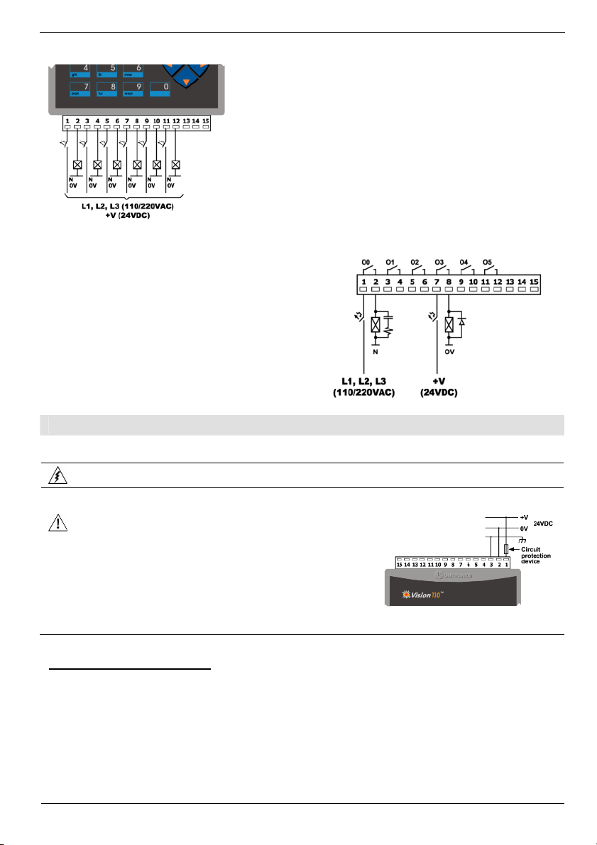
encoder Inputs, 6 Relay Outputs
This guide provides basic information for Unitronics’ controller model V130-33-R2.
General Description
V130 OPLCs are micro-OPLCs, rugged programmable logic controllers that comprise:
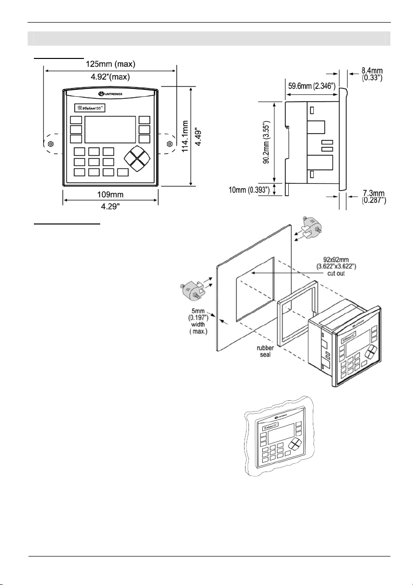
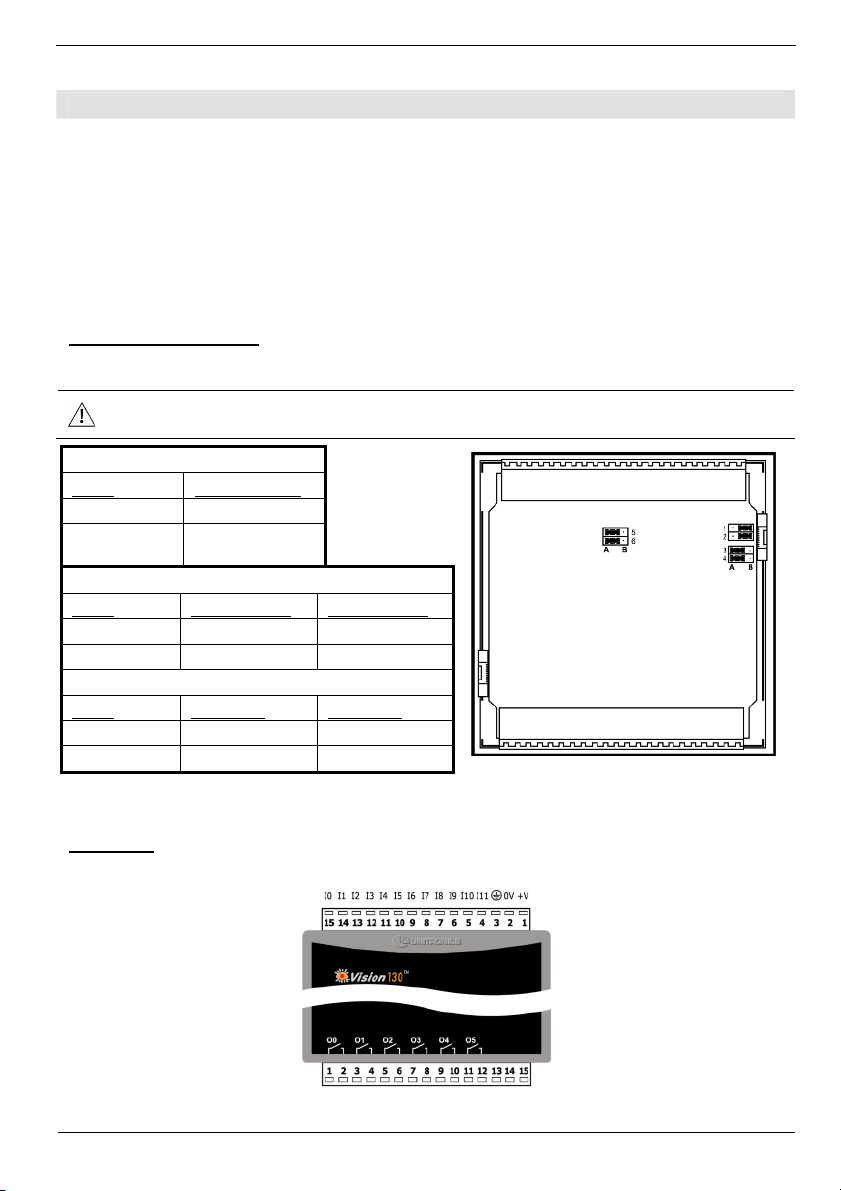
On-board I/O configuration
Built-in operating panel containing an LCD and a keypad
Communications 1built-in serial port: RS232/RS485
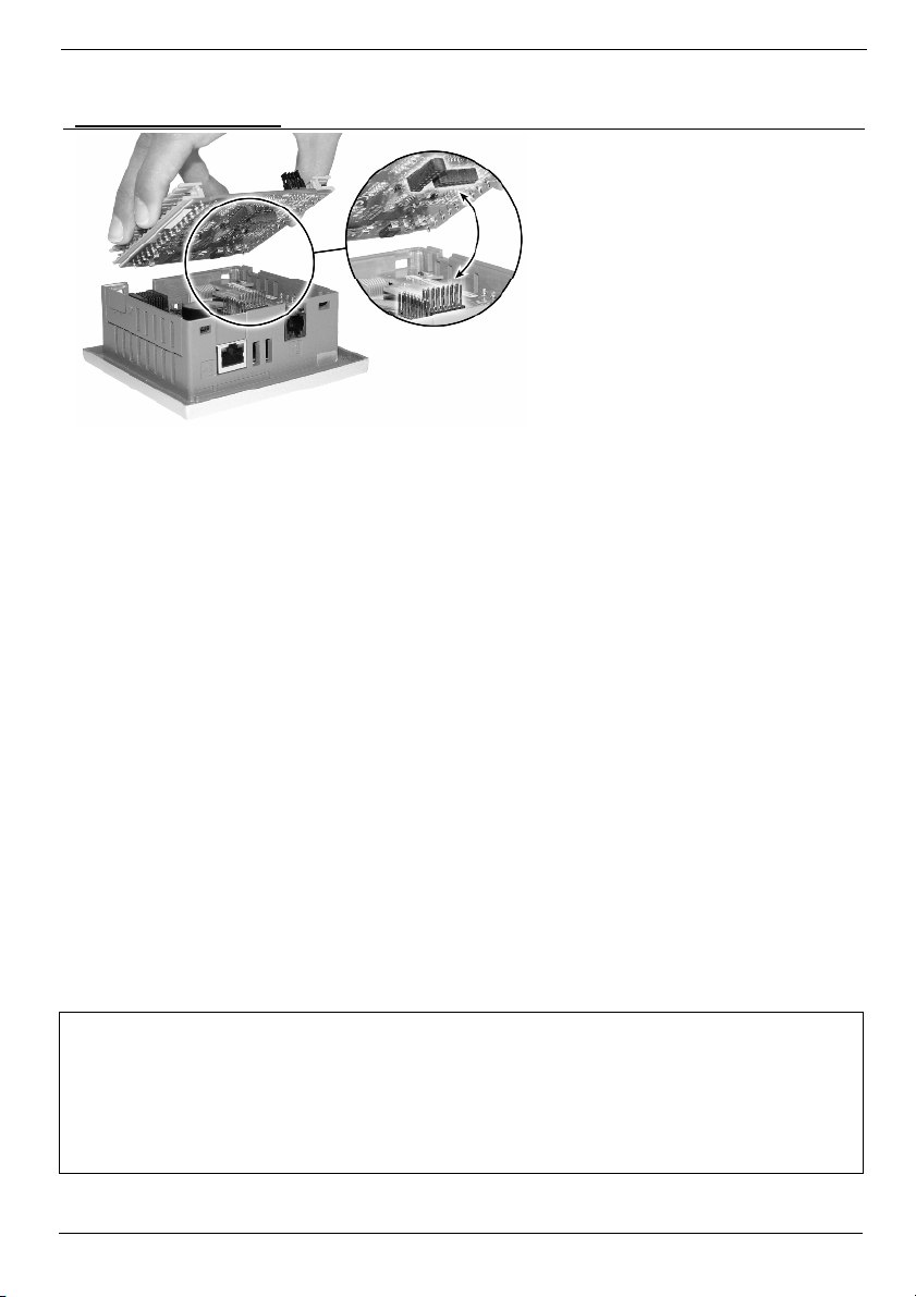
Optional: the user may order and install
one or both of the following modules:
-RS232/RS485/Ethernet
-CANbus
Communication Function Blocks include:
SMS, GPRS, MODBUS serial/IP. Protocol
FB enables PLC to communicate with
almost any external device, via serial or
Ethernet communications
I/O Options V130 supports digital, high-speed, analog,
and temperature measurement I/Os via:
On-board I/O configuration
Model-dependent
I/O Expansion Modules
Via adaptor, use up to 8 I/O Expansion
Modules, add up to 128 additional I/Os
Information Mode This mode enables you to:
View & Edit operand values, COM port settings, RTC and screen
contrast/brightness settings
Stop, initialize, and reset the PLC
To enter Information Mode, press the <i> button for several seconds.
Programming
Software,
&Utilities
The Unitronics Setup CD contains VisiLogic software and other utilities
VisiLogic
Easily configure hardware and write both HMI and Ladder control
applications; the Function Block library simplifies complex tasks
such as PID. Write your application, and then download it to the
controller via the programming cable included in the kit.
Utilities
Includes UniOPC server, Remote Access for remote programming
and diagnostics, and DataXport for run-time data logging.
To learn how to use and program the controller, as well as use utilities such
as Remote Access, refer to the VisiLogic Help system.
Data Tables 120K dynamic data (recipe parameters, datalogs, etc.),
192K fixed data (read-only data, ingredient names, etc)
Additional product documentation is in the Technical Library, located at www.unitronics.com,and on
the Unitronics’ Setup CD.
Technical support is available at the site, and from support@unitronics.com.