Universal Audio 1181 User manual

CX ENCODER/DECODER MODEL
1181
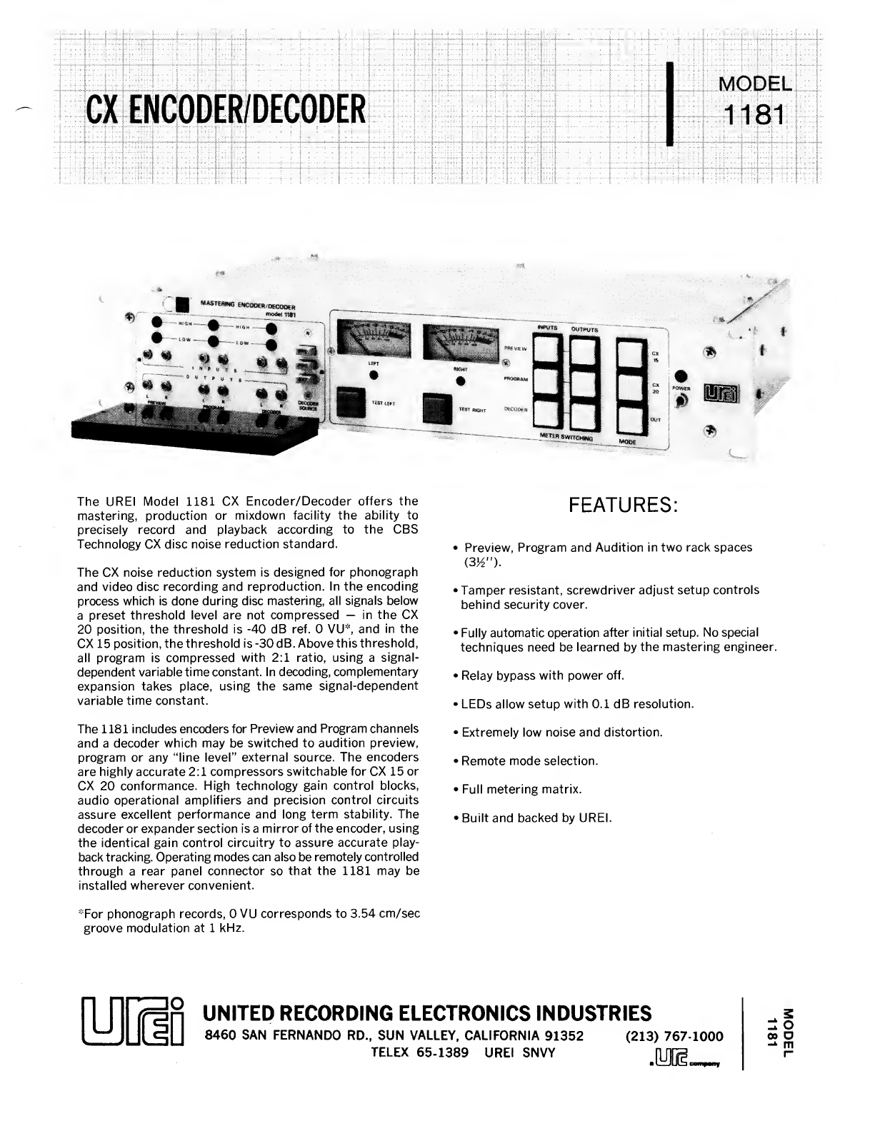
The UREI Model 1181 CX Encoder/Decoder offers the
mastering, production or mixdown facility the ability to
precisely record and playback according to the CBS
Technology CX disc noise reduction standard.
The CX noise reduction system is designed for phonograph
and video disc recording and reproduction. In the encoding
process which is done during disc mastering, all signals below
apreset threshold level are not compressed —in the CX
20 position, the threshold is -40 dB ref. 0VU*, and in the
CX 15 position, the threshold is -30 dB. Above this threshold,
all program is compressed with 2:1 ratio, using asignal-
dependent variable time constant. In decoding, complementary
expansion takes place, using the same signal-dependent
variable time constant.
The 1181 includes encoders for Preview and Program channels
and adecoder which may be switched to audition preview,
program or any “line level” external source. The encoders
are highly accurate 2:1 compressors switchable for CX 15 or
CX 20 conformance. High technology gain control blocks,
audio operational amplifiers and precision control circuits
assure excellent performance and long term stability. The
decoder or expander section is amirror of the encoder, using
the identical gain control circuitry to assure accurate play-
back tracking. Operating modes can also be remotely controlled
through arear panel connector so that the 1181 may be
installed wherever convenient.
*For phonograph records, 0VU corresponds to 3.54 cm/sec
groove modulation at 1kHz.
FEATURES:
•Preview, Program and Audition in two rack spaces
(3V2").
•Tamper resistant, screwdriver adjust setup controls
behind security cover.
•Fully automatic operation after initial setup. No special
techniques need be learned by the mastering engineer.
•Relay bypass with power off.
•LEDs allow setup with 0.1 dB resolution.
•Extremely low noise and distortion.
•Remote mode selection.
•Full metering matrix.
•Built and backed by UREI.
UNITED RECORDING ELECTRONICS INDUSTRIES
8460 SAN FERNANDO RD., SUN VALLEY, CALIFORNIA 91352
TELEX 65-1389 UREI SNVY (213) 767-1000 MODEL
1181

TECHNICAL SPECIFICATIONS
ELECTRICAL; (Each Channel)
Inputs
Input Impedance
Input Level
Outputs
Output Load
Power Output
Frequency Response
Distortion
Control Law
Noise (Encoder)
(Decoder)
CONTROLS:
Front Panel
Metering
LEDs
External Connections
Power Requirements
Environment
PHYSICAL:
Dimensions
Finish
Weight
Shipping Weight
Accessories
Balanced bridging differential amplifiers, six each,
:10 kohms, used as balanced input.
5kohms, used as unbalanced (single ended) input.
:+20 dB maximum (Ref. 0.775 Vrms).
:Floating, transformer isolated, six each.
:600 ohms or greater.
:+24 dBm into 600 ohm load (12.28 V).
:+0, -0.5 dB, 20 Hz -20 kHz.
:Less than 0.1% THD, 50 Hz —15 kHz, at worst case gain.
:According to CBS Technology CX Standard, CX 15 or CX 20.
:Program -95 dB.
Preview -85 dB.
.(Referred to Input; Ref. 0.775 Vrms).
:Output -83 dB (15.7 kHz BW),
-95 dB (A-weighted).
Input Gain, Output Attenuator Trims, Meter Switches, Mode Switches,
Power Switch.
Two Meters, switch selectable to read any Input or Output.
“0” Reference +4 dB (Ref. 0.775 V).
Six LEDs to precisely indicate 1kHz, 3.54 cm/sec “0” point during setup.
Power LED.
Rear chassis barrier strips for inputs and outputs, plus barrier strip for remote
control of operating mode. Power through 3-wire lEC style connector.
110-120 VAC, or 220-240 VAC, 50/60 Hz, switch selectable, 25 watts.
Special option: 1181-100 Vfor 100 Voperation.
Operating 0°C to +50°C. Storage -20°C to +60°C.
483x89mm rack panel, depth behind panel 305mm (19 in x3)^ in x12 in).
Panel is 3.18mm (Vb in.) brushed clear anodized aluminum.
Chassis is cadmium plated steel.
7.5 kg (16.5 pounds).
9.3 kg (20.5 pounds).
Security Cover, SC 1181, included.
100 Vpower option available on request (1181-100 V).
6/82 1.5MF printed in U.S.A.

BEFORE PROCEEDING WITH COMPLETE UNPACKING AND SETUP,
CONSULT UNPACKING AND INSPECTION INSTRUCTIONS ON PAGE 2
model 1181
CX ENCODER/DECObER
United Hecording Electronics Industries
B46D BAN FERNANDO ROAD, SUN VALLEY, CALIFORNIA 91352
(818) 767-1000
Printed in U.S.A.
©Copyright 1981, UREI

UREI -1181 CX ENCODER/ uECODER
Preliminary Operating Instructions
SECTION I
Genera
1
Des cription :
The Model 1181 is designed to facilitate the cutting of master discs
to the C.B.S. standard for the CX process. Basically the process consists
of soft but precise compression during the mastering process and playback
through precise expansion to recreate the original dynamics with a15 to
20 dB reduction in perceived surface noise.
Jopolp^x
The 1181 consists of two stereo encoding (compression) sections designed
nominally to be used in the preview and program feed to the mastering
lathe, and astereo decoder (expander) to audition playback or feedback
from the lathe. Inputs are balanced differential amplifiers (5532 op amps)
and outputs are transistor boosted 5532 amps followed by very high quality
isolation transformers. Voltage controlled gain is facilitated with Allison
Research EGC 101 's.

SECTION II
INSPECTION AND INSTALLATION
Unpa cking and Inspec tion
Your Model 1181 was carefully packed at the factory, and the container
was designed to protect the unit from rough handling. Nevertheless, we
recommend careful examination of the shipping carton and its contents for
any sign of physical damage which could have occured in transit.
If damage is evident, do not destroy any of the packing material or the
carton, and immediately notify the carrier of apossible claim for damage.
Shipping claims must be made by the consignee.
The shipment should include:
Model 1181 CX Encoder/Decoder
UREI Preliminary Instructions
Two-Part Warranty Card bearing the
same serial number as the Model 1181
Rack mounting hardware
Env ironmen ta1Cons iderations
The system will operate satisfactorily over arange of ambient temperatures
from 0°C to +50° (+32°F to 122°F), and up to 80% noncondensing relative
humidity.
If the system is installed in an equipment rack with high heat producing
equipment (such as power amplifiers), adequate ventilation should be provided
in order to assure longest component life. Also, while circuitry susceptible
to hum pick-up is sufficiently shielded from moderate electromagnetic fields,
installation should be planned to avoid mounting the system immediately
adjacent to large power transformers, motors, etc.
Powering
The 1181 may be operated from either 115 -125 VAC or 220 -240 VAC mains
(50 Hz or 60 Hz, single phase). The nominal line voltage may be selected
with arear panel switch. BE SURE TO VERIFY BOTH THE ACTUAL LINE VOLTAGE,
AND THE SETTING OF THE VOLTAGE SELECTOR SWITCH BEFORE CONNECTING THE 1181
TO THE MAINS. (For operation in Japan (lOOV mains) aspecial power supply
transformer is required.)

SECTION III
SET-UP AND CALIBRATION
This procedure assures accurate adherence to the CBS CX noise reduction
standard with regard to level matching the compression curve.
The input sensitivity is adjusted first using the input trim controls and
then the output level is matched to the input for unit gain at the
calibrated level. The standard calibration level is 3.54 cm/second for
asingle channel (or 5cm/second mono combined).
Equipment required:
1. Small screwdriver to adjust trimpots on front panel.
2. Test record with 5cm/second 1000 Hz test tone.
Note: 5cm/second (lateral) may not be the standard used for "0" level
in your facility. Nevertheless all CBS compatable decoders are referenced
to 5cm/second and therefore if proper playback at the comsumer level is to
be had this procedure must use 5cm/second for the test level.
Procedure:
For this procedure the 1181 is presumed to be patched between the mastering
console output and the cutting chain input. The decoder input should be
connected to the feedback/playback output of the cutting chain. These con-
nections may be permanent without concern about affecting non -CX operation
1n any way, as the signal is normal led through relays when the 1181 is off
or in bypass.
1. Bring up a1kHz tone on the output of the mastering console
equivalent to 5cm/sec lateral (3.54 cm/sec each channel).
If there is any question about the level, cut atest laquer
and compare it on playback to astandard level 5cm/sec disc,
such as the CBS' SRT-101.
2. With 3.54 cm/sec tone at the input of encoder press the "TEST LEFT"
button and adjust preview and program left input trimpots to
extinguish the "high-low" LEDs.
3. Press the test right button and adjust the preview and program right
input trimpots to extinguish the high-low LEDs. This completes the
preview and program input level set-up.
4. Select CX 15 or CX 20 mode. Press "PREVIEW INPUTS" meter switch
and note the readings on left and right meters. Press the
"PREVIEW OUTPUTS" meter switch and adjust the preview Land R
trimpots for the same readings as at the imputs (unity gain).
Caution: It's very easy and very frustrating to adjust the
wrong trim pots in this step. The output pots are the bottom row.
Next press the "PROGRAM OUTPUTS" meter switch and adjust the
"L and RPROGRAM" outputs for ameter match to the program
inputs as was done on preview.

Chec king Cal ibrat i
o
n
:
1. With the 3.54 cm/sec tone at program and preview inputs,
press "TEST LEFT" no LEDs should light. Press "TEST RIGHT"
no LEDs should light. Press CX 20.
2. Check program input levels with meters. Check program output
levels with meters. They should match the inputs.
3. Check preview inputs and outputs. (As above)
De coder Set- up:
1. Play the 3.54 cm/sec test record through the decoder. Press
"TEST LEFT" button and set decoder "L INPUT" trimmer to extinguish
LEDs. Repeat this test for the right channel.
2. Next, set the decoder outputs (lower controls) to level match the
inputs (CX 20 mode/CX 15 mode).

SECTION IV
MAINTENANCE
General
The Model 1181 is an all solid-state unit, ruggedly constructed with only
the highest quality components. As such, it should provide years of
trouble free use with normal care. All parts used are conservatively
rated for their application, and workmanship meets the rigid standards
you have learned to expect in UREI products.
NO SPECIAL PREVENTIVE MAINTENANCE IS REQUIRED.
Repairs and Warranty
This product is factory warranted to the original purchaser against defects
in material and workmanship for one year after initial purchase. This
limited warranty must be activated at the time of purchase by returning
the registry portion of the Warranty Card to the factory. Should amalfunction
ever occur, the dealer from whom the unit was purchased will be glad to handle
return for factory repair. Please call or write to the factory for aReturn
repairs. For prompt service,
shio the unit prepaid directly to the factory with the R^ Number visibl
e
on
the shipp inq 1abe 1.Be sure it is well packed in asturdy carton, witTi
shock-absorbing material such as foam rubber, styrofoam pellets, or "bubble-
pack" completely filling the remaining space. Particular attention should
be paid to protecting the controls, switches, etc. Tape anote to the top^
of the unit describing the malfunction, and instructions for return. We will
pay one-way return shipping costs on any in-warranty repair.
Because of specially selected components in this product, field repairs are
not authorized during the warranty period, and attempts to perform repairs
may invalidate the warranty.
Even if your unit is out of warranty, we recommend that you return it to
the factory for repairs. Our experienced personnel, supported by special
test equipment, will be able to find and eliminate any problem in the most
efficient way.
WARN ING :The full AC Line voltage is present at
several points inside the chassis. Be careful to
avoid personal shock when you work on the unit
with the covers removed.

CX LICENSING INFORMATION
The CX noise reduction system provides a20 dB reduction in the
background groove noise ("surface noise") of adisc record, while
permitting the original program source to be reproduced without
systematic alterations. This requires that the compression used in
recording and the expansion used in playback be complementary
processes. To assure correct record and expander performance, as
well as consistent product identification, CBS Inc. is making available
licenses for CX audio disc encoding and CX playback apparatus, both
of which require adherence to established technical specifications and
CX identification. The CX encoding license is royalty-free, permits
use of the CX trademark only on records encoded according to CX
specifications.^*^ This will result in standardization in the audio
record industry and avoid public confusion, as well as assure
interchangeability of CX records and CX playback equipment.
To obtain aCX encoding license (or CX playback apparatus license)
or further information, please contact the Patent Counsel, CBS Tech-
nology Center, 227 High Ridge Road, Stamford,CT. 06905, telephone
(203) 327-2000.
The encoding specification is essentially confirmed by using a
properly operating UREI model 1181, producing arecord cali-
brated in accordance with the instructions contained within this
manual.

Ncn .cnwt?.v*\bt

0K50t[|]
VCA 30\
NZUV4
,C^^30'9 A
[mM003
DteowL?.
\HPUT
+1SV
ls6K®* 111 @
RH'bOS-B'^
lO^ d, SS3^
>,\HP\iT VCA 3.0L
NAOQViLt
S\N\TOi\mC-i
fYP\tA\_ ,?K,OG.P.M<#k, AY4b
1b ^^10
M\S 8
cn" 5
CZ3
@
^1z
00D
1
0
IM
IUECOBEH
SOURCt S^N\^CWW&
BOTTDW\ WE'W
T-IPUAV. K16\ .K2I» .KVM
rCRW\ -<K\0\ Eci5Z0\ -<Kiaoi ML(r.^a\ -<»,»)
SCHEMATVC
CX CViCCIKR/itCDBER
ute.1 mscx l»i.NNtMb mo.
I\8(

HCTTtS UYiV.t'bS CnvCt?s\N\St

K50^@ K50>d]
VCA ^0\
TV\01b\i\-t.
OOZl
:>1K
P.VA\0\-S
,o^^^
TOUTPUT
SSoi 0^01 @
AA
^ytUfWU
ir^ .101301-6
fci c5 tiOK.
f
>1?
1,\HP\iT
RfeOfcS.^4—,R\(aHT
I
Iten&i
MSOK “t- ^
ywaot
^1 1lOVf
VCA •^)0^
NAOYiUU^
RH7>0S-B^ "®,
lOR fc 55^ TOL.M SNN\TCW\H(b
R5\7
\.SY.
»/iW i5®/«.
R5\S
l/iW X5•/%>
RS^T.
\.SR
1/2NN ±5Vo
ra'*^
W^15 a
1i6
aCD
="
t§)
<(3 2.
00D
1
D
IHPUT
R\6«TCQM^ »®-aSo
HECOBER
SOURCE svNncms
{\ BT £.
BOTtoWl N\£.'W
T»ni>t K\M 1K.201 .KVll
'
‘V
2rCR\ft\ 5mO\ j(CRZ0\ ^KZDt j[CA^O\ J
FROM ?0 ?0 n-H
7.Sf. »r1
,RHVR’0
»(OR
1
KAoh^iu
-3 *W-' «
4ft^ST
V
/OK
iieiLv
SCHENkATVC
CX EYKODBR/M-UIBER.
UTl| WSSC.V |im.K««\Hb MO.
R»\e\ llt'JS
m.W. X.T.MNKM IS*Bt \\-»l-a\
I


'I 5
pe&£/ ir]fl9{e.B-/np /y?oGf,f,ca::f/ojn
/. /SO^ytc^ 'Jy^'€yy}plni^^i> /n CZh^t n
7)cijf 300 ^rx. /'0^>/i»-/o/'2- fIXGj 2.1^j2'2^fS)
Add si^|\e. cAf> /A yi>ii
7
i^kJI c^/
I—,^^,, ,/*wr C-C^/ ^
/>)o<s' <7^/eA9/fe.// <*'d 9QG colAu, 10 juP q%
3. c:/as^ 5=^7 uoiH^.i^d'
V- ^//6//2. 2//, ;?/Z oolfu. ,0/S ^^yM/^
dj^ccok.
f^od (7d^S pr<e.-e.r>^ph<t6,}s
-t^^
/^/5 mcsi?' ao-uie.^ cp eh/i&6ho/d sArff, noa;t<s,
Ti-’&£>ponS'uQ^ /a h's!^ P<^ep.c<-<z-ncxy.
./ /•'/3> P
~y 6(db p&T' c>cJ/oue^ p/c^nn .
^/7 /o<f> /38 h/^ue. iiGAO/dsdiz. /jdP-^Ds&d/}xx/
Sn /(s/ '*-/^3 c/e.ct:>de^ oA/y b^^fP-spieje^d/?x>s/.

SECTION III
SET-UP AND CALIBRATION
Scope ;
This procedure assures accurate adherence to the Pioneer Laser Vision noise
reduction standard with regard to ievel matching the compression curve.
The input sensitivity is adjusted first using the input trim controls and then
the output level is matched to the input for unity gain at the calibrated level.
The standard calibration level Is AQ% modulation at 1kHz.
Eg uipmen tReg u[red ;
1. Small screwdriver to adjust trimpots on front panel.
2. Test recording with 1000 Hz test tone at 40^ modulation.
Procedure ;
For this procedure the 1181 is presumed to be patched between the mastering
console output and the recorder input. The decoder input should be connected to
the playback output of the recording chain. These connections may be permanent
without concern about affecting non -CX operation In any way, as the signal Is
norma Iled through relays when the 1181 Is off or in bypass.
1. Bring up a1kHz tone on the output of the mastering console eg uIvalent to
40^ modulation.
2. With the A0% tone at the Input of encoder press the "TEST LEFT" button and
adjust preview and program left input trimpots to extinguish the "high-
low" LEDs.
3. Press the "TEST RIGHT" button and adjust the preview and program right
Input trimpots to extinguish the high- low LEDs. This completes the
preview and program Input level set-up.
4. Select CX 15 mode. Press "PREVIEW INPUTS" meter switch and note the
readings on left and right meters. Press the "PREVIEW OUTPUTS" meter
switch and adjust the preview Land Rtrimpots for the same readings as at
the inputs (unity gain). Caution: It’s very easy and very frustrating to
adjust the wrong trimpots In this step. The output pots are the bottom
row. Next press the "PROGRAM OUTPUTS" meter switch and adjust the "L and
RPROGRAM" outputs for ameter match to the program Inputs as was done on
preview.
Checking Cal Ibrat ion ;
1. With the 40^ modulation tone at the program and preview Inputs, press
"TEST LEFT". No LEDs should light. Press "TEST RIGHT". No LEDs should
light. Press CXI 5.

2. Check program input levels v/ith meters. Check program output levels with
meters. They should match the inputs when the encoder Inputs are at the
A0% Ievel
.
3. Check preview inputs and outputs (as above).
Decoder Set-u p:
1. With a40% tone at the decoder Inputs press "TEST LEFT" button and set
decoder "L INPUT" trimmer to extinguish LEDs. Repeat this test for the
right channel
.
2. Next, set the decoder outputs (lower controls) to level match the Inputs.

«ff’'=i'j»s:5T' 5?w^sc'Sjsr^'i^rf:^'"=3an3«5»i;f!Sfi»yKfaMsaaBr^b«R»iMr«i«5<M^ oa^^'^a a^atffvsn es «
Cg3" CX COMPRESSION SPECIFICATIONS FOR LASERVISION VIDEODISCS
General
To improve the dynamic range of the audio program on the laser
optical videodisc, an optional companding technique is recommended.
This technique has been developed by the CBS Technology Center and
is known as CX, Use of this system for videodisc players or discs
is only permitted if alicense has been executed with the CBS
Technology Center. The version of CX for LaserDisc has been
'modified from the standard CX for LP's or other videodisc formats,
and those CX encoders/decoders will not yield optimum results for
LaserDisc. The technique is compatible in that the program, if
encoded in the CX format, can be played back on adecoding player
or anon-decoding player. If played on adecodin'* player the full
benefit of 14 dB noise reduction will be achieved Playback on a
non-decoding player will be completely satisfactory but will not
yield noise reduction improvement.
To assure, optimum compatibility between disc and player, it is
essential that all disc manufacturers encoding discs for the CX
process use the same reference level parameters to ensure aspecific
correspondence between the static compression curve of the encoder
and the modulation level of the audio carriers on the videodisc.
Similarly, all player manufacturers incorporating CX decoders
should arrange operating levels to match the prescribed disc
characteristic.
Encoding Characteristics
1.Statics
The static encoding characteristic of the CX system, optimized for
LaserDisc use is shown in Figure 1. The figure describes the
static gain relationship between the input signal level to the
encoder, in dB, referenced to standard operating level, and the
audio subcarrier modulation in dB re 100% modulation. Note that
the modulator gain should be adjusted such that standard 0db
operating level at 1KHz produces 40% modulation +0.5 dB (+40 KHz
deviation) and at the limit, +16 dB input will produce 100%
modulation (+100 KHz deviation) +0.5 dB.
The diagram also indicates that the "knee", the point on the
compressor characteristic curve below which a1:1 gain correspon-
dence exists between input and output, should occur 28 dB +0.5 dB
below standard operating level.
-1-8/12/82

Table of contents
Other Universal Audio Media Converter manuals
Popular Media Converter manuals by other brands

Schindler
Schindler Cube Plus user manual

Vicon
Vicon VN-901T installation guide

Sundrax
Sundrax DALIGate DIN user manual

Whelen Engineering Company
Whelen Engineering Company E1000 Installation and operating manual

Trivum
Trivum InStreamer Quick installation guide

Sumavision
Sumavision EMR3.0 operating instructions