Universal Flow Monitors FlowStream FP-EF-2N-360SCFH-CO2-X1B User manual

UNIVERSAL FLOW MONITORS, INC.
1755 East Nine Mile Road
PO Box 249
Hazel Park, MI 48030-0249
TEL (248) 542-9635 FAX (248) 398-4274
http://www.flowmeters.com
™
Laminar Mass Flowmeters
User Manual
Series: FP

FPMAN-1-190214 Page 2
TABLE OF CONTENTS
PROPRIETARY NOTICE............................................................................................................. 3
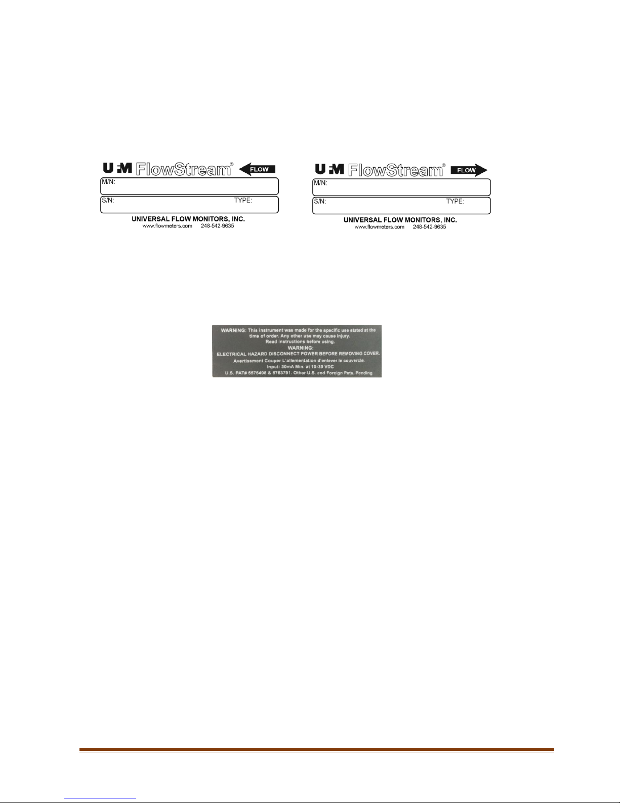
NAMEPLATE EXAMPLE............................................................................................................ 4
ELECTRICAL SAFETY LABEL ................................................................................................. 4
GENERAL SPECIFICATIONS .................................................................................................... 5
ELECTRICAL SPECIFICATIONS............................................................................................... 5
OPERATION................................................................................................................................. 6
APPLICATIONS ........................................................................................................................... 6
Using FlowStream at Varying Temperatures............................................................................. 6
Reference Conditions for Mass Flow Measurement.................................................................. 7
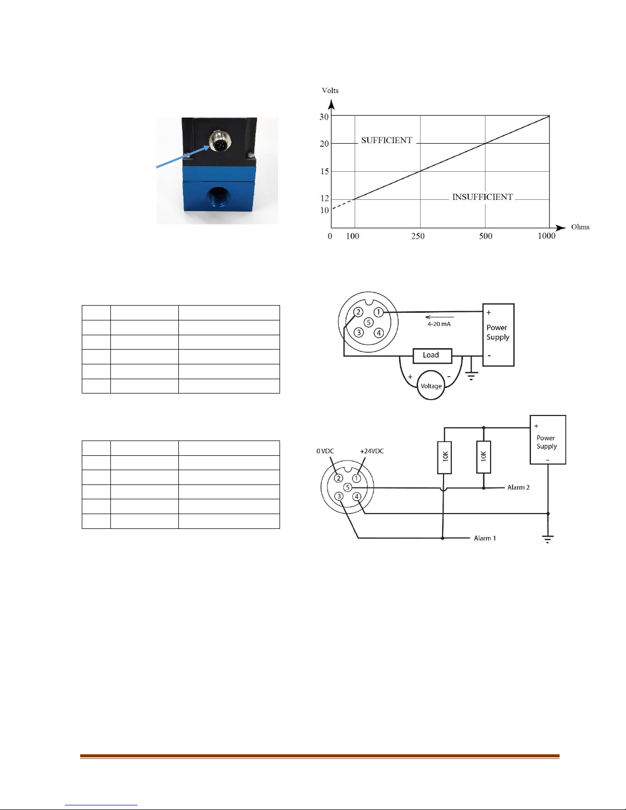
WIRING DIAGRAMS................................................................................................................... 8
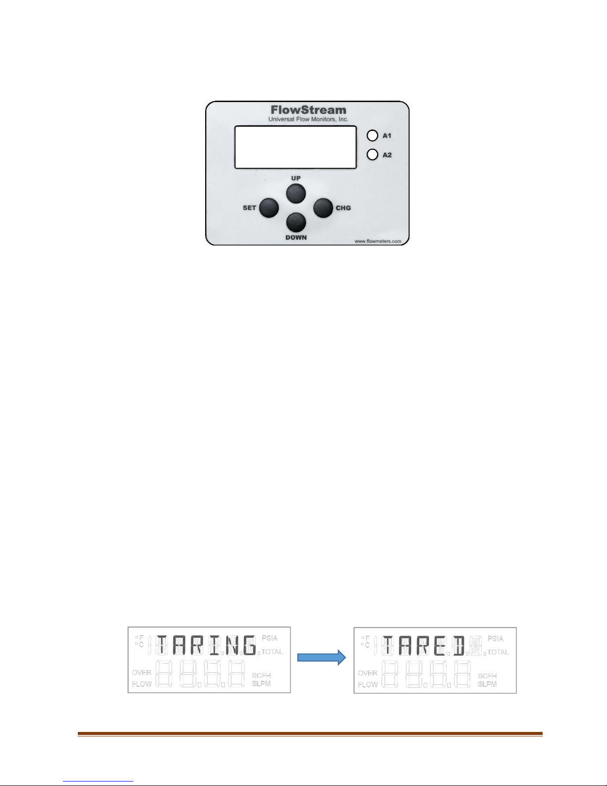
KEYPAD OPTIONS...................................................................................................................... 9
USER MENU............................................................................................................................... 10
FLOW HI ................................................................................................................................. 10
FLOW LO................................................................................................................................ 11
OUTPUT SPAN....................................................................................................................... 11
THRESH .................................................................................................................................. 11
AVG......................................................................................................................................... 12
GAS.......................................................................................................................................... 12
USER FACTOR....................................................................................................................... 12
RESET...................................................................................................................................... 13
EXIT......................................................................................................................................... 13
AVAILABLE FLOW SIZES....................................................................................................... 14
ORDERING INFORMATION.................................................................................................... 15
DIMENSIONS
............................................................................................................................. 17
RETURN MATERIAL
AUTHORIZATION
............................................................................... 18
WARRANTY INFORMATION.................................................................................................. 20

FPMAN-1-190214 Page 3
PROPRIETARY NOTICE
The information contained in this publication is derived in part from proprietary and patented
data. This information has been prepared for the express purpose of assisting in installation,
operation, and maintenance of the instruments described herein. Publication of this information
does not convey any rights of use or reproduction other than in connection with the installation,
operation and maintenance of the equipment described herein. Universal Flow Monitors, Inc.
reserves the right to change the information contained in this publication at any time and without
prior notice.

FPMAN-1-190214 Page 4
NAMEPLATE EXAMPLE
ELECTRICAL SAFETY LABEL
Serial numbers are formatted as YY MM ID 000
YY = year, MM = month, ID = product identifier, 000 through 999 = three-digit sequential
number.
FP-EF-2N-360SCFH-CO2-X1B

FPMAN-1-190214 Page 5
GENERAL SPECIFICATIONS
Flow Ranges: 2 SLPM/5 SCFH F.S. to 1300 SLPM/2600 SCFH F.S.
Turndown Ratio: 400:1
Accuracy: ± 1% of reading
Repeatability: ± 0.2% of full-scale
Maximum Measurable Flow: Up to 125% of full-scale, gas dependent
Pressure Effect on Accuracy: Less than ±0.04% of reading/ PSI
Temperature Effect on Accuracy: Less than ±0.04% of reading/ °F
Response Time: 100 msec
Pressure Drop: 2.5 PSI at maximum flow (port to port), gas dependent
Gases: Air, Argon, Nitrogen, CO2, Oxygen, Helium, Hydrogen,
Methane, and user selectable
Gas compatibility: Non-corrosive, non-condensing
Maximum Operating Pressure: 150 PSIG
Sensor Burst Pressure: 200 PSIG
Operating Temperature: -25 to 80 °C (-13 to 176 °F)
Process Connections: 1/8”-1/4”-3/8”-1/2”-3/4” NPT. SAE, BSPT, BSPP also available
Display: Rate, total, pressure, temperature, multi-gas, alarms, engineering
units
Wetted Parts: Sensors: Ceramic, silicon, gold, epoxy, RTV
Flow body: Stainless steel, anodized aluminum, Viton®
Enclosure Rating: Type 4
ELECTRICAL SPECIFICATIONS
Analog output: 4-20 mA (2-wire loop powered)
Alarms: 2 independent open-collector outputs (high/low flow rate)
Open-Collector Rating: 30VDC at 50 mA
Electrical Connection: 5-pin connector
Supply Voltage: 10–30 VDC
Supply Current: 22 mA @ F.S. flow (includes over-range)

FPMAN-1-190214 Page 6
OPERATION
FlowStream flowmeters accurately measure the mass flow rate of most gases. The flow rate is
determined by measuring the pressure drop across a unique internal restriction, known as
Laminar Flow Element (LFE). The restriction is designed such that the gas molecules are forced
into moving in parallel paths along the entire length of the passage for the entire range of
operation of the device. Unlike other pressure-flow measuring devices, the relationship between
pressure drop and flow is linear in laminar flowmeters.
FlowStream mass flowmeters utilize an absolute pressure sensor along with a temperature
sensor to compensate for density variations of the gas. When combined with the differential
pressure (volumetric flow) output, the mass flow rate of the gas can be determined.
Laminar Flow Illustration
APPLICATIONS
FlowStream flowmeters are designed to work with non-corrosive, non-ionic, clean, dry gases
only. Introduction of liquids to the internal sensors will damage the unit, and the repair is not
covered under warranty. Relative humidity of the gas can be as high as 100%, as long as proper
installation guarantees that no internal condensation will occur. A 50-micron filter and/or dryer
may be required for some applications.
Using FlowStream at Varying Temperatures
Even though FlowStream flowmeters measure true mass flow, rapid variations in ambient
and/or gas temperature may affect performance. This is due to the time lag of the internal
temperature sensor and the slow heating and cooling of the flowmeter body. It is highly
recommended that through proper installation the following two objectives be met:
There be minimal difference between gas temperature and ambient temperature;
Rapid temperature variations be avoided.

FPMAN-1-190214 Page 7
Since the temperature sensor is embedded inside the sensor block, if ambient temperature is
different from gas temperature, there would be a discrepancy between what the sensor reads and
the true gas temperature. The flowmeter body would track ambient temperature while gas
temperature would heat/cool the body at a different rate.
Likewise, if temperature variation is rapid, the flowmeter body may not follow it quickly enough
due to the mass of the metal flow chamber, which in turn would result in inaccurate
measurement of gas temperature.
For optimal performance, always allow two to four hours from the time the ambient and gas
temperatures are stabilized to when the first flowmeter reading is taken.
Reference Conditions for Mass Flow Measurement
Although the correct units for mass are expressed in grams, kilograms, etc., it has become
somewhat standard that mass flow rate is specified in SLPM (standard liters per minute), SCFH
(standard cubic feet per hour) or other similar units.
This means that the mass flow rate is calculated by normalizing the volumetric flow rate to some
standard temperature and pressure (STP). By knowing the gas density at that STP, one can
determine the mass flow rate in grams per minute, kilograms per hour, etc. STP is usually
specified at sea level conditions; however, no single standard exists for this convention. UFM
uses STP of 70° F and 14.7 PSIA.
Note: If used outside the parameters specified in this manual, the proper operation of the
flowmeter cannot be guaranteed.

FPMAN-1-190214 Page 8
Load Resistor vs. Power Supply
WIRING DIAGRAMS
4-20 mA Output
Pin
Wire color
Function
1
Brown
+24VDC
2
White
0VDC
3
Blue
N/U
4
Black
N/U
5
Gray
N/U
4-20 mA with Alarm Option
Pin
Wire color
Function
1
Brown
+24VDC
2
White
0VDC
3
Blue
Alarm 1
4
Black
Common
5
Gray
Alarm 2
Alarm wiring example:
Using 10K pull-up resistors,
Alarm 1 or 2 output is pulled high when deactivated and goes to ground when activated
(transistor conducting).
Power Connector
5 Pins

FPMAN-1-190214 Page 9
KEYPAD OPTIONS
UP: Consecutive (short) button press cycles between the following information on top of the
display.
a. Gas: Current selected Gas
b. Pressure: Gas pressure in PSI
c. Pressure: Gas pressure in PSIA
d. Totalizer: Total volume of gas according to the selected units.
e. Temperature: Temperature in degree Celsius
f. Temperature: Temperature in degree Fahrenheit
Options are saved in the memory so that next time you turn the power on it will remember
the display settings.
DOWN: Consecutive button press cycles between the different flow units in SCFH and SLPM.
Once selected, the setting is saved into the memory of the device.
To reset the totalizer, press SET until the LCD shows “TARING”. Release the SET button
immediately, and the totalizer will be reset.
To tare the meter (at zero flow) press SET until the LCD shows “TARING”. Keep holding the
SET button (for 5 seconds) until the LCD shows “TARED” and the flow output will be set to
zero.
5 seconds

FPMAN-1-190214 Page 10
CHG: Pressing CHG once shows the user menu. Once the desired menu item is selected, you
can do one of the following:
To change the set points
Press SET to choose the particular menu item.
Consecutive pressing of SET will cycle through the different digits of the set point.
Press UP or DOWN to increase or decrease the particular digit. Pressing SET will set
the digit.
Long press SET until “SAVED” is displayed on the upper row of the LCD.
Press CHG to exit out of current menu item and change the next item.
To change Gas Setting
Consecutive pressing of SET will cycle through the different Gas options.
Once the desired gas is selected, keep holding the SET button down until “SAVED”
is displayed on the upper row of the LCD.
To exit out of the menu
Navigate to “EXIT” menu item with consecutive CHG presses. Press SET to exit out. An
alternative option is to not touch any buttons for 5 seconds, as the program will exit the
user menu after 5 seconds of inactivity. Note: this option does not save the recent
settings.
USER MENU
FLOW HI: High set point for flow alarm. (This example shows the detailed steps for changing
a set point. All other menu items use the same method.)
Press the SET button to change. Range is 0-100% FS. If set to 0, alarm is disabled. Alarm
hysteresis is 1% FS.
When first digit starts blinking, use the UP and
DOWN buttons to adjust the digit, then press SET to
move to the next digit.
Blinking

FPMAN-1-190214 Page 11
When finished, keep holding the SET button down
until “SAVED” is displayed, then release the SET
button.
FLOW LO: Low set point for flow alarm.
Range is 0 to FLOW HI –2% FS. If set to 0, alarm is
disabled. Alarm hysteresis is 1% FS.
Use SET, UP, DOWN buttons as explained above to
change the set point.
OUTPUT SPAN: Scale the 4-20mA output
Range is 50% to 120% of factory calibration. For
example, if the flowmeter was originally ordered for
360 SCFH (20 mA=360 SCFH), you can scale the
output to read 20 mA as low as 180 SCFH or as high
as 420 SCFH for ease of measurement at user-specific
flows.
THRESH: Threshold percentage for filtering noisy flow readings.
Use SET, UP, DOWN buttons as explained above
to change the set point.
The filtering algorithm can detect outliers and
exclude them from signal averaging. The Threshold
value (in percent) determines which samples will be left out. Percentage is with respect
to the internal moving average. Range is 3-50%. For example, when Threshold is set to
20%, if the moving average is 100 SCFH and a single flow sample is either above 120
SCFH or below 80 SCFH (i.e. 20% of the average), it will be ignored and not added to
the moving average.However, if subsequent samples are all outside the threshold band,
then they will be counted in and the moving average is updated with the new values
(more than one sample signifies a real change in flow, not noise).

FPMAN-1-190214 Page 12
AVG: Moving average array size.
Use SET, UP, DOWN buttons as explained above
to change the set point.
This is the number of samples that are averaged
when calculating the flow. Range is 1-100. Samples
are added to the internal moving average array and a new output is displayed once every
100 msec.
GAS: Current Gas.
Use the SET button to change the gas.
Pre-programmed gases are: Air, Argon, CO2,
Helium, Nitrogen, Methane, Hydrogen, Oxygen.
USER FACTOR:
Range is 0.200 to 2.000. The LCD will show this
factor x1000 (i.e. without the decimal point). It is
implied that there are 3 decimal places (e.g. 1000
means 1.000).
You can use as many gases with the flowmeter as
you wish. If the gas is not on the pre-programmed list, you can enter the gas factor in this
menu. Please note that the flowmeter accuracy may be degraded as much as 5% of full-
scale when using this option (depending on the accuracy of the gas factor and the nature
of the gas itself). There are other factors involved in accurately measuring different gases
as well.
Note 1: If you change this factor to any values other than 1.000, you must use Air in your
gas selection; otherwise, there will be a “double-correction” applied to the output.

FPMAN-1-190214 Page 13
RESET: Reset the parameters back to the original factory settings.
Hold the SET button until the letters RESET will be
displayed on the LCD one by one. This will provide
a 5 second delay that is intended to prevent and
accidental reset.
The following variables will be reset to their original values:
20MA = Full-scale set at the factory
High flow alarm = 80% of FS
Low flow alarm = 20% of FS
Threshold = 20%
Moving average = 25
GAS = Air
USRFCT = 1.000
EXIT: Exit the user menu.

FPMAN-1-190214 Page 14
AVAILABLE FLOW SIZES
Each size is offered in several optimized maximum flow rates as shown in the table below.
These configurations provide the highest accuracy and turndown ratios stated in the
specifications. Please refer to the model code in the Ordering Information section to select the
desired flow rate.
Port
size
Max SCFH
Air, N,
O2, CO2,
He,
Methane
Max
SLPM Air,
N, O2,
CO2, He,
Methane
Max SCFH
Argon
Max
SLPM
Argon
1/8”
5
2
3
1.5
30
15
20
10
60
30
45
20
1/4"
120
60
90
45
240
120
180
90
360
180
270
135
3/8"
360
180
270
135
480
240
360
180
600
300
450
225
1/2"
600
300
450
225
720
360
540
270
840
420
630
315
960
480
720
360
1080
540
810
405
1200
600
900
450
1320
660
990
495
1440
720
1080
540
3/4”
1440
720
1080
540
1560
780
1170
585
1680
840
1260
630
1800
900
1350
675
1920
960
1440
720
2040
1020
1530
765
2160
1080
1620
810
2280
1140
1710
855
2400
1200
1800
900
2500
1250
1890
945
2600
1300
1980
990

FPMAN-1-190214 Page 15
ORDERING INFORMATION

FPMAN-1-190214 Page 16

FPMAN-1-190214 Page 17
DIMENSIONS

FPMAN-1-190214 Page 18
NOTICE
RETURN MATERIAL
AUTHORIZATION
Please
read the
following
UFM policy
information carefully.
By
following
the
guidelines
outlined
below
you will
assist
in
providing
a
timely evaluation
and
response regarding
the
status
of your
flowmeter.
UFM
evaluates
all
AUTHORIZED RETURNED MATERIALS
in a timely
manner
and will
promptly
provide notification regarding the status
of
the related materials and/or
a
written
quotation
indicating the total charges and description of the necessary
repairs.
1.
All returns must have
a
RMA form completed by the customer.
2. Any
meter returned
that was
previously
in
service must have
the
OSHA requirements completed and
a
MSDS included where
applicable.
3.
An RMA number will only be issued when UFM has received
a
copy of the completed RMA form
and
any
applicable
MSDS.
4. A
“Return Goods” shipping label (located
in
the back
of
the Instruction Manual) must
beused
for returning
materials to
UFM.
5.
Returned goods must be shipped prepaid or they will be rejected.
REPAIRABLE MATERIAL
Written
or verbal
authorization
to
proceed
with the repair under an
assigned
Purchase Order
must be
received within
30
days
of
repair quotation.
If the
unit(s)
is
repaired,
the
$90.00 evaluation charge
will be
applied
to
the quoted repair costs.
If
no
repairs are authorized within this 30-day period, the customer will
be
billed $90.00 plus
shipping charges and the materials will be returned to the
customer.
NON-REPAIRABLE MATERIAL
If
materials are found non-repairable,
a
written notice that
the
material
is
non-repairable
willbe
provided
to
the customer by UFM.
If
no disposition to scrap or return the material
is
received from the customer within
30
days, non-repairable material will be scrapped
and the customer will be billed the $90.00 evaluation
charge. If a UFM
replacement
unit is
purchased
within 30 days of
non-repairable condition notice,
the $90.00
evaluation
fee will be
waived.
The return of
non-repairable materials
may be
ordered
by a
customer Purchase Order; shipping and handling charges will be assumed by
customer.
RETURN FOR RESTOCK
All goods returned for restock adjustment
must
be:
A. New and unused.
B. Returned to the factory within ONE YEAR of date of original
shipment.
C. Returned through the distributor where the goods were originally purchased.
D. Returned material will be subject to an evaluation charge of
$90.00.
The
customer
will be
advised
of the
restocking adjustment
for all
restockable goods.
Upon
customer’s
acceptance of the restocking adjustment, the $90.00 evaluation fee will
be waived and UFM will issue
a credit
to the customer. The customer will be advised of
any
non-restockable
goods and will be charged the
$90.00
evaluation fee plus any
shipping charges
if
goods are returned to the
customer.

FPMAN-1-190214 Page 19
If no
disposition
is
received
by
UFM within
30
days,
the
goods
willbe
scrapped and
the
$90.00 evaluation fee will be
billed.
WARRANTY RETURNS
Warranty returns must
be
shipped prepaid
to
UFM. UFM
will
review
the
goods and
advise
the
customer
of the
evaluation
and
validity
of the
warranty claim. Valid warranty
claims
will be
repaired
or
replaced
at no
charge.
No
evaluation
fee will be
charged
for
repairs made under warranty. Return shipping costs
willbe
prepaid by UFM. Should
UFM determine returned material not
to
be defective under the provisions
of UFM’s
standard warranty,
the
customer
will be
advised
of
needed repairs
and
associated
costs.
All materials
returned
for
warranty repair
that are
determined
not to
have
a
valid warranty claim
will be
subject
to the
“Repairable Material”
policy outlined
above.

FPMAN-1-190214 Page 20
WARRANTYINFORMATION
1) ACCEPTANCE AND INTEGRATION CLAUSE: This Sales Order Acknowledgment and the sales
order information that Universal Flow Monitors, Inc. ("Universal") attaches to or associates with it (herein
"Acknowledgment"), constitutes an acceptance by Universal of an offer by the buyer upon the conditions and
terms and at the prices stated in this Acknowledgment. The Acknowledgment contains the entire
understanding of Universal and the buyer regarding the subject matter of said Acknowledgment. This
Acknowledgment may only be modified by a written agreement signed by the party against whom
enforcement is sought.
2) WAIVER: Waiver by Universal of any default(s) by the buyer shall not constitute waiver by Universal
of any of the conditions of the agreement between Universal and the buyer as set forth hereunder with respect
to any further or subsequent default by the buyer.
3) FORCE MAJEURE: Universal shall not be responsible for failure or delays in deliveries due to
fire, strikes, breakdowns, acts of God, failure of carriers, inability to secure required materials, or other
causes beyond Universal's control. Buyer waives any claims for damage arising by virtue of delay in delivery
of material by Universal.
4) LIMITED WARRANTY:
(a) Warranty. For a period of one year from the date of manufacture, Universal warrants that each product
covered by this Acknowledgment will be free from defects in material and workmanship. In order to qualify
for any remedy provided in this Acknowledgment, buyer must give notice to Universal within the one-year
period, return the product to Universal freight paid and intact with Material Safety Data Sheets covering
all substances passing through the product or that form a residue on the product.
(b) Exclusive Remedy. The buyer's EXCLUSIVE REMEDY for failure of any product to conform to any
warranty or otherwise for any defect is, at Universal's sole option: (i) repair; (ii) replacement; or (iii) refund
of the entire purchase price for the specific product. Without limiting the foregoing, in no case will Universal
be liable for de-installation of any defective product or installation of any repaired or replaced product. THIS
REMEDY I S THE EXCLUSIVE REMEDY AVAILABLE TO THE BUYER OR ANY OTHER
PERSON. UNIVERSAL SHALL NOT BE LIABLE FOR ANY DIRECT, INDIRECT, INCIDENTAL,
CONSEQUENTIAL, SPECIAL, PUNITIVE, OR OTHER DAMAGES IN CONNECTION WITH ANY
CAUSE OF ACTION, WHETHER IN CONTRACT, TORT, OR OTHERWISE.
(c) Disclaimer of Other Warranties. The express warranty in this Acknowledgment is in lieu of any other
warranty, express or implied. Without limiting the foregoing, UNIVERSAL DISCLAIMS THE IMPLIED
WARRANTY OF MERCHANTABILITY AND ANY IMPLIED WARRANTY OF FITNESS FOR A
PARTICULAR PURPOSE.
(d) Special Note About Fitness for a Particular Purpose. This website and other materials of Universal may
placeproductsinto,ordisplayproducts in,categoriesaccordingtofunction, size, construction, materials, or other
property. This is for organizational purposes only and NO PLACEMENT OF ANY PRODUCT IN ANY
CATEGORY OR ANY PRESENTATION OF A PRODUCT IN RELATION TO OTHER PRODUCTS
WILL CONSTITUTE A WARRANTY OF FITNESS FOR APARTICULAR PURPOSE.
5) PROHIBITED USES: As a condition of the sale of goods or services, buyer will not use, sell, distribute,
or otherwise transfer for use, or permit to be used, sold, distributed, or otherwise transferred any product
purchased from Universal for any of the following uses:
(a) Nuclear Energy Applications. Any application involving, directly or indirectly: (i) exposure of any
product to any hazardous properties of nuclear material; (ii) dependence on the proper functioning of
the product for the operation of a nuclear facility by any person or organization; (iii) use in or for any
equipment or device used for the processing, fabricating or alloying of special nuclear material if, at any
time, the total amount of such material on the premises where such equipment or device is located consists
of or contains more than 25 grams of (A) Plutonium (any isotope) or Uranium 233 or any
combination thereof; (B) more than 250 grams of Uranium 235; (iv) use in, or for the control of any aspect
of, any structure, basin, excavation, premises or place prepared or used for the storage or disposal of waste.
The foregoing include, without limitation, any application involving nuclear material contained in spent fuel
or waste that is possessed, handled, used, processed, stored, transported or disposed of, any application related
to the furnishing of services, materials, parts or equipment in connection with the planning, construction,
maintenance, operation or useof any nuclear facility.
This manual suits for next models
1
Table of contents
Other Universal Flow Monitors Measuring Instrument manuals
Popular Measuring Instrument manuals by other brands

PCB Piezotronics
PCB Piezotronics 482C27 General operations manual

Endress+Hauser
Endress+Hauser Tank Side Monitor NRF590 technical information

PCE Instruments
PCE Instruments PCE-PMI 3 Instruction

Thermokon
Thermokon EPM300 quick start guide

Gedore
Gedore 8200-01 operating instructions

Digi-Sense
Digi-Sense 20250-19 user manual