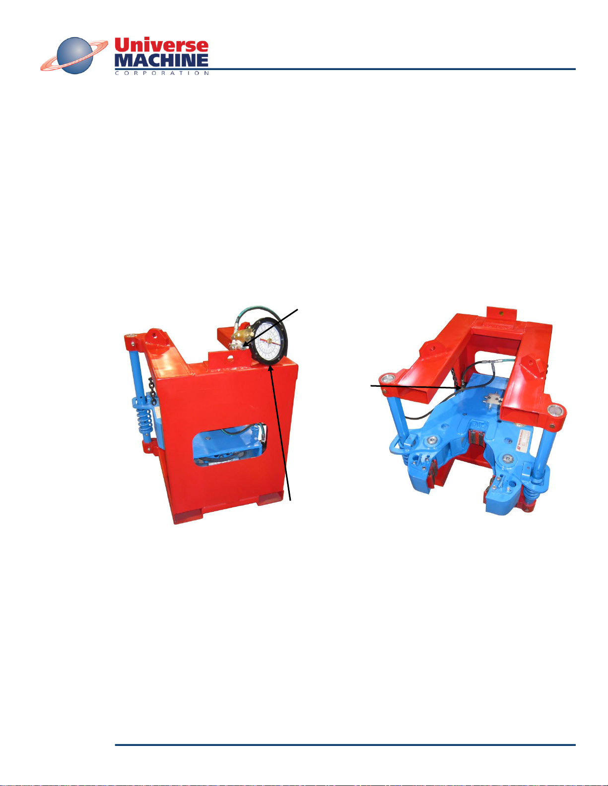
10-5/8 HYDRAULIC BACKUP
Model 02F10E
1.0 INTRODUCTION
The Universe Hydraulic Backup Unit is designed to attach to a Power Tong and to bite either tubing or
casing in order to hold the tubular from rotating while the Tong unscrews or screws together the
threaded joint.
The Unit is carefully designed and built to be sturdy and reliable. The unit design ensures years of
trouble-free performance. Like any fine mechanical device, the regular maintenance and safety
procedures covered in this manual will help extend the life and performance of this unit as well as
provide for safe and efficient operation.
It is therefore very important to read this manual carefully before using the Hydraulic Backup Unit.
This manual also covers the major components that make up the Hydraulic Backup Unit. Although this
machine is built to meet rigorous and tough working conditions, some parts over time may wear out and
need replacing. If any replacement parts are required, or if you experience problems that this manual
does not cover and need assistance, please contact any of our Universe dealers.
2.0 SPECIFICATIONS
2.1 HYDRAULIC BACKUP UNIT
Overall Dimensions (Without Tong): 32-3/8” wide x 35” long x 33-1/2” high
(0.66 m wide x 0.89 m long x 0.85 m high)
Weight (Frame & Backup): 800 lbs. (363 kg)
Maximum Torque: 25,000 ft-lbs. (3,456 kg-m)
Torque Arm: 24” (0.61 m)
Maximum Operating Pressure: 3,500 psi (24,132 kPa)
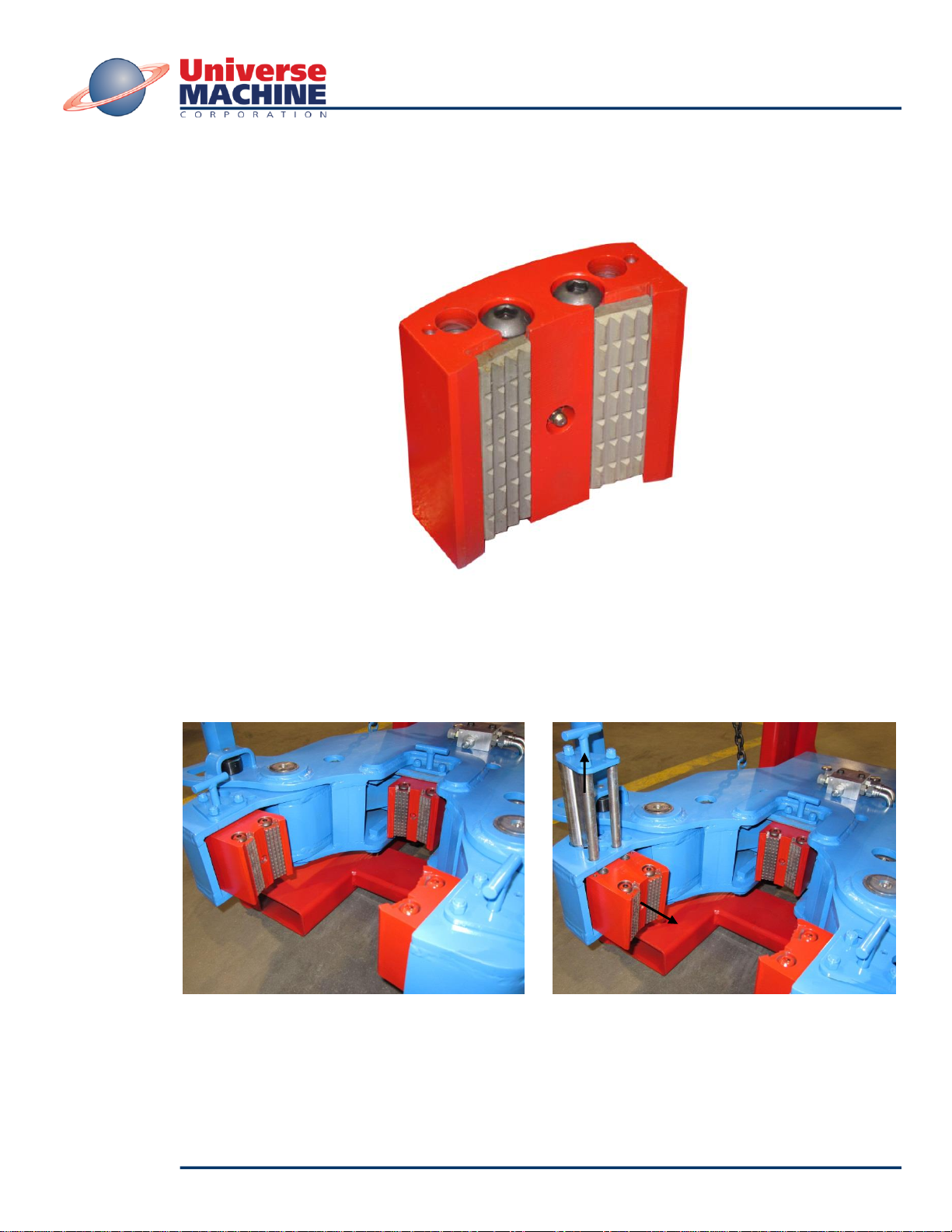
Insert Die Jaw Sizes / Range Available:
JAW SIZE RANGE
9-5/8” (244.5 mm) 8-1/2” to 9-5/8” (215.9 mm to 273.1 mm)
8-5/8” (219.1 mm) 7-1/2” to 8-5/8” (190.5 mm to 219.1 mm)
7-5/8” (193.7 mm) 6-1/2” to 7-5/8” (165.1 mm to 193.7 mm)
7” (177.8 mm) 5-7/8” to 7” (149.2 mm to 177.8 mm)
6-5/8” (168.3 mm) 5-1/2” to 6-5/8” (139.7 mm to 168.0 mm)
5-1/2” (139.7 mm) 4-3/8” to 5-1/2” (111.1 mm to 139.7 mm)
4-1/2” (114.3 mm) 3-3/8” to 4-1/2” (88.9 mm to 114.3 mm)
2.2 HYDRAULIC OIL (Factory Default)
For normal operation (approximately between -18 to 40 deg. °C (0 to 104 deg. °F)), the hydraulic oil
should be based on the following specifications:
- Mineral based oil 22cST –56cSt (100 SSU –250 SSU) at 40 °C (104 °F).
- Additives to resist corrosion, oxidation and foaming.
- Viscosity should remain at 22 cSt (100 SUU) at 21 °C (70 °F).
NOTE: Specifications of hydraulic oil may vary depending on environmental conditions. It is
recommended to refer to a hydraulic fluid consultant to ensure the proper oil is specified for
harsh or extreme environments.