Uno International BOXER 9100 User manual

uno.
Uno International Ltd.
20 Belsize Avenue
London NW3 4AU
UK
Tel.: +44 20 7794 4080
The CE sign certifies that the instrument
meets the requirement of the EEC
directives and has been tested according
to the specified test methods.
It is the stated philosophy of Uno
International Ltd to preserve the
environment wherever possible.
Uno International Ltd. will only use
materials and production techniques that
cause least environmental damage.
User Manual
ISS1/14
Electronically controlled
dispensing pump
BOXER 9100
Box contains
The following:
Boxer 9100 pump controller ...........................................................Cat. No. 9110.000
PSU output 24V 1A with universal plug adapters...........................Cat. No. 9200.004
Set tube clips No. 1......................................................................... Cat. No.9000.601
Set tube clips No. 2......................................................................... Cat. No.9000.602
Set tube clips No. 3......................................................................... Cat. No.9000.603
(1)IDØ2.0mm Silicone tube—1 metre ............................................Cat. No. 9000.509
(2)In line connector tube to yellow tip....................................................Cat. No. 3923
(3)Tip holder support.................................................................... Cat. No. 9100.3003
(4)Yellow Dispense Tip 1-100µl LW1035..............................................Cat. No. 3530
This instruction manual ..................................................................Cat. No. 9110.003
Accessories & spares:
Silicone Tubing IDØ1.0mm complete with connectors..................... Cat.No.9000.504
Silicone Tubing IDØ2.0mm complete with connectors..................... Cat.No.9000.505
Silicone Tubing IDØ3.0mm complete with connectors..................... Cat.No.9000.510
Santoprene Tubing IDØ1.0mm complete with connectors...............Cat.No.9000.501
Santoprene Tubing IDØ2.0mm complete with connectors...............Cat.No.9000.502
Santoprene Tubing IDØ3.0mm complete with connectors...............Cat.No.9000.518
Santoprene tubing ID Ø1.00mm1meter running length.................... Cat.No.9000.521
Santoprene tubing ID Ø2.00mm1meter running length.................... Cat.No.9000.506
Santoprene tubing ID Ø3.00mm1meter running length.................... Cat.No.9000.515
Silicone tubing ID Ø1.00mm1meter running length.......................... Cat.No.9000.507
Silicone tubing ID Ø2.00mm1meter running length.......................... Cat.No.9000.509
Silicone tubing ID Ø3.00mm1meter running length.......................... Cat.No.9000.508
Bag of 25 Yellow Dispense Tips1-100µl LW1035 ............................Cat.No.9100.005
Spare dispense set consisting of above items 1-4 ........................Cat. No. 9100.006
Unoverse 9100 wall mounting bracket/stand ...................................Cat.No.9100.001
Foot Switch ............................................................................................ Cat.No. 6013
Product Specification:
Mains Voltage ............................................................ 100V-240V 0.3A MAX 47-63Hz
Power Supply Unit output ......................................................................+12VDC 0.5A
Environmental operating temp ............................................................+10°C to +40°C
Environmental storage temp .................................................................+4°C to +40°C
Environmental operating RH.................................................................................90%
Environmental storage RH....................................................................................95%

Acetaldehyde Chloroacetic acid Linseed Oil Potassium salts
Acetic acid Chronic acid Magnesium salt Silver salts
Acetic Anhydride Chromium salts Maleic acid Soap solutions
Acrylonitrile Copper salts Manganese salts Sodium salts
Aluminum Chloride Ethylene glycol Mercury salts Sodium hydroxide
Aluminum sulfate Ferric salts Methanol Sodium hypochlorite
Ammonia Fluoborate salts Natural gas Stearic acid
Ammonium salts Fluoboric acid Nickel salts Sulfur dioxide
Ammonium hydrox-
ide Fluosilicic acid Nitric acid-10% Sulfuric acid, dil.
Amyl acetate Formaldehyde Nitroethane Sulfurous acid
Antimony salts Formamide Nitrogen oxides Tannic acid
Arsenic salts Formic acid Nitrous acid Tanning extracts
Barium salts Glucose Oils, animal Trisodium phosphate
Benzoic acid Glycerins Oils. mineral Urea
Bleaching liquor Hydrochloric acid Oils. vegetable Uric acid
Boric acid Hydrocyanic acid Oxalic acid Water
Bromine Hydrogen peroxide Oxygen Water (brine)
Butyric acid Hydrogen sulfide Phosphoric acid Water (stoam)
Calcium salts Iodine and solutions Phthalic acid Zinc salts
Carbon Dioxide Lactic acid Phosphoric acid
Chlorine (wet/dry) Lead salts Plating solutions
Acetates Butane Me Et Ketone Skydrol 500-B4
Acetone Butanol Nitric acid-30% Sulfuric acid-90%
Alcohols Essential Oils Nitrobenzene Tetrahydrofuran
Amyl alcohol Ethers Oleic acid Turpentine
Aniline Ethanol Phenol
Benzaldehyde Furfural Propanol
Benzyl alcohol Lithium grease Pyridine
Benzene Cyclohexane Kerosene Nitric acid- 70%
Carbon tetrachloride Ethyl chloride Trichloroethylene Perchloroethylene
Chlorobenzene Freon Lacquer Toluene
Chloroform Gasoline, unleaded Naphtha Xylene
Little or no effect on Santoprene
Severe Moderate effect
Chemical compatibility chart 1. A. Unpacking
Remove the packing materials, unpack the pump controller and the power supply unit.
Make sure that you have got all the components as specified in ’Box Contains’ last page of
this manual.
Please contact your supplier if you notice any one of the components is missing or
damaged.
Note: Do not attempt to assemble a unit using damaged components.
Retain the packaging so it can be used for future shipping.
The plug-in power supply unit is Switch Mode and automatically adjusts itself to the mains
power supply characteristics. It will work with any mains voltage supply from 100V to 240V.
The power supply unit is shipped with three alternative plug adaptors to fit European,
American and UK power outlets. Select the correct adaptor for your needs and clip it into
the power supply.
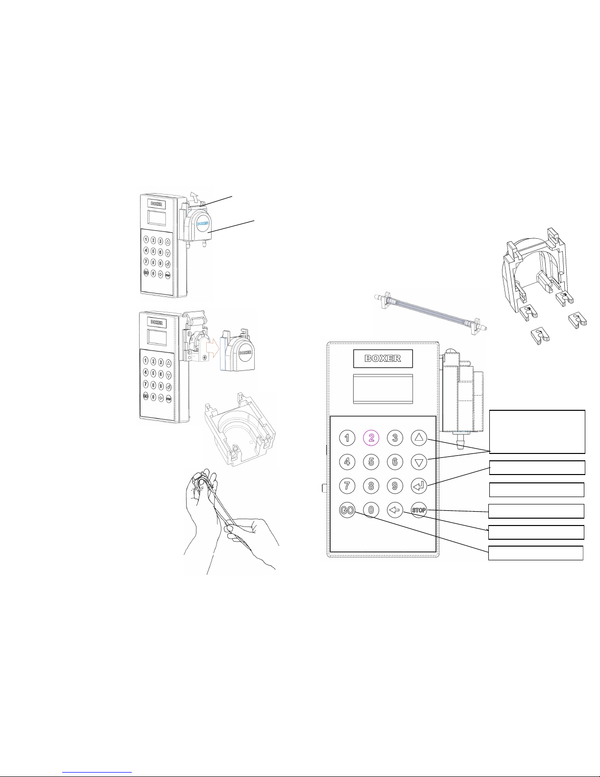
2. General information on peristaltic pumps
Peristaltic tube pumps are ideal for fluid transfer, metering and dispensing. In contrary to
centrifugal and gear pumps, peristaltic pumps handle fluids of various viscosities, are self
priming and can operate in either flow direction.
With no valves, seals or packing to come in direct contact with the pumped fluid, they are
ideal for pumping high purity & corrosive fluids and for contamination free dosing.
The principle of the peristaltic pump is based on a tube which is occluded by a series of
rollers. As a general rule, the higher the number of rollers and the smaller the tube
diameter—the lower are the flow rates but better is the accuracy and precision.
The 9100 controller is equipped as a standard with 3 roller system and Ø2.0mm ID tube.
This tube diameter together with maximum speed delivers a flow rate of 48ml/min.*
The highest dispense accuracy is achieved by using a semi rigid tube on the outlet of the
pump. We recommend thin wall tubing such as FEP or PVC tube.
*83ml/min for the 9110.010 which has max rotor speed of 520rpm

Page 1
3. The peristaltic tube
The supplied peristaltic tube is made
from Silicone. Please make sure the
reagents you intend to use are
compatible with these material.
3. A. Clamping the peristaltic tube
The pump controller is delivered with a
IDØ2.0mm Silicone tube.
Move the lever up to open the clamp and
remove the clamp from the pump.
Insert the tube into the two tube holders
on each side of the tube clamp and
make sure the tube follows tangent and
the arc of the clamp.
Push the tube clamp back onto the pump
and lower the lever—the tube is now
occluded by the rollers.
3.B. Releasing the peristaltic tube
when you have finished
Whenever the pump is not in use for long
periods of time it is important to release
the pressure off the tube. This will
reduce tube deformation and ensure that
accuracy/precision is maximised.
Release the pressure by lifting the
pressure lever
3.C. Replacing the tube
Tube need replacing when worn out or
wherever you intend to change the
dispense volume range in which you
work—for smaller or larger dispense
volumes.
Lift the pressure lever and replace the
tube, making sure that you have installed
the tube centrally and that the tube is
fully engaged by the tube guides.
.
Page 2
Pressure lever
Clamp
4. The choice of tubing
The unit can work either with fixed length tubing—75mm long within the tube clamp, or with
continuous tubing which in effect does not have any length restriction. In both cases, the
correct tube clips have to be installed in the clamp.
For the continuous tubing there are three sizes of tube clips:.
1. Marked ‘1’ for ID1.0mm tube
2. Marked ‘2’ for ID 2.0mm tube
3. Marked ‘3’ for ID 3.0mm tube
Clip No. 2 is used for the fixed length tubing.
Page 3
5. The Control Panel
U/D keys
Scroll menu
Choose range
Increase or decrease value
when in calibration mode
Enter
STOP dispense
GO—start dispense
Back space/Escape
Numeric entry keys

Power socket for 24V DC 1A
6. Preparing the pump for use
Plug the supplied PSU into your power socket and the low voltage plug into the socket on the
left side of the unit, switch it on by pressing the ‘ON’ button. The green LED on the side and
the display will illuminate indicating that the unit is operational.
The display will temporarily read ‘BOXER 9100’ and then the display will show the value it
has in it’s memory.
Note the direction of flow. The pump can be reversed in flow direction using the slide switch,
so that you can aspirate any unused reagent back into the reservoir.
Page 4
Pump direction slide switch:
Front = Bottom side dispenswe
Back= Bottom side aspirate
Remote pulse socket for connection to foot switch
(Accessory) or pulse from a robotic processor
Accepts Ø2.5mm mono or stereo plug
On/Off switchPower ‘ON’ LED
Page 5
IMPORTANT: CHOOSE THE RANGE THAT MATCHES THE ONE YOU ARE MOST
LIKELY TO USE IN YOUR APPLICATION.
7. Choosing the correct working range
There are 4 working ranges to choose from. These working ranges correspond to tube
diameters. The decimal point is shifted corresponding with the working range.
R1 ID Ø0.5mm for < 9ml max display 9.000ml
R2 ID Ø1mm for < 25ml max display 25.000ml*
R3 ID Ø2mm for < 90ml max display 90.000ml
R4 ID Ø3mm for <190ml max display 190.0ml
* The single µl digit can not be entered in R2 & R3
Working with low volume dispenses with large diameter tube will
reduce both precision and accuracy of dispenses.
Using the U/D keys scroll to the screen displaying “Range Enter?”
Press Enter.
Using the U/D keys choose the range corresponding to your tube
diameter and press Enter.
The display will show the last volume you worked with at that
particular range.
8. Gravimetric pump calibration procedure
Pump flow performance is subject of many factors among them the condition of the
peristaltic tube and the viscosity of the reagent. It is therefore important that you calibrate the
pump before it is commissioned using your reagent and at periodic intervals.
Carry out the calibration procedure using a volume nearest to the volume yiou are most likely
to dispense. You can choose any volume.
1. Carry out 5 identical dispenses into a vessel and establish the
gravimetric volume dispensed in each operation.
2. Calculate the mean dispensed volume.
3. Using the U/D keys scroll to display saying “Calibrate Enter?”
4. Press Enter
5. The display shows “C” to indicate that you are in the
calibration mode and next to it the range which you calibrate
i.e. 1 to 4.
6. Using the U/D keys correct the volume to your calculated
mean volume *
7. Press Enter and the display shows the volume you intended to dispense. The unit is
now calibrated with a particular tube within your chosen working range.
* Volumes in R2 & R3 will increment by steps of 10µl
The unit will store the calibration you carried out for each individual range.

Page 6
9. Prime the tube
To prime the tube direct the dispense tube towards the reservoir and hold down the GO key.
As soon as the tube is primed, release the key and the pump will stop.
10. Entering the dispense volume
Press 1 to 0 to enter your required volume. Note that the digits move from right to left with
the decimal point staying stationary. The unit will always display on the top line the range in
which you are working.
To correct an error entry press the back space key.
Press GO to start dispensing.
The unit will remember the volume only for this single
dispense. Following this dispense, the unit will revert to
the previously displayed volume. In order to enter the
typed volume into the unit’s memory, press the Enter
button after entering the volume.
11. The STOP button
The STOP button will stop the dispense immediately. The unit “remembers” the remaining un
dispensed volume it will display the amount you dispensed so far. Press GO and the unit will
dispense the remainder of the volume you originally wished to dispense.
If you prefer the unit to “forget” the remaining volume press the ESCAPE key after you
pressed the STOP key. The unit will display the last volume you entered.
12. Changing the pumps direction
The pump controller can be used for dispensing or aspirating reagents. The slide switch on
the left side of the unit sets the direction that the pumps’ rotor rotates.
You can not change direction when the pump is in dispense mode. You can however press
the STOP key, change direction by moving the slide switch, and continue by pressing the GO
key allowing the pump to dispense or aspirate the remainder of the entered volume in the
reversed direction.
Page 7
13. Interval Dispense
You can set the unit to dispense any volume for a number of times in predefined intervals.
This feature is useful in repeatable operations either in manual mode or when the dispense
head is held by a robotic arm. Intervals can be set between 0.5 sec to 100 minutes.
To set repeat dispensing:
1 Using the U/D keys scroll to the screen saying “Interval
Enter?”
2 Press Enter and you are asked to enter the Delay in
minutes and seconds. Any number up to 99:59 will be
accepted whereby any number bigger than 59 for the
seconds will be rejected. Using the numeric keys enter
the numbers of minutes and seconds. The number ‘00.00
represents ½ second. Press Enter to confirm.
3 Repeats screen asks you to enter the number of
repeats—from 1 to 98. Entering 99 repeats will result in
continuous number of dispenses which can only be
stopped by pressing the STOP button. Using the numeric
keys enter the number of repeats. Press Enter to confirm
4 You can exit the interval mode by pressing the ESCAPE key.
14. Pump speed adjustment
To adjust the dispense speed scroll the menu using the U/D arrows until the “Speed Enter?”
Is displayed. Press Enter and the screen will display Speed with 8 bars on bottom line. Use
the U/D keys to increase or decrease number of bars. More bars
represent higher speed. Press the Enter key to enter the desired
speed into the instruments memory.
15. Continuous dispense mode
To run the pump continuously scroll the menu using the U/D arrows
until “Constant Enter?” Is displayed. Press Enter and the screen will
display “Constant Stop/Go”. Press the “GO” button to start the pump
and the ”STOP” button to stop it at any point.
Press the ESCAPE key to leave the continuous dispense mode.
Please note: running the peristaltic tubes dry over a long period will
shorten their life.

Page 9
18. Exclusion
If the equipment is used in a manner not specified by the manufacturer, the protection
provided by the equipment might be impaired.
This instrument is NOT suitable for use in explosion hazard environments.
This equipment is not suitable and should not be used for medical applications.
19. FAQ
1. Q. Why does the pump stalls or runs slower than expected when new tubing is
installed?
A. A new tube is stiff when new so has to be shaped for some time before it gains it’s
elasticity. Run the pump in continuous mode for a total of approx 5 minutes with the
clamp lever half open to start with, gradually moving the clamp lever to fully closed
position.
2. Q. I have entered a volume but nothing happens after pressing the GO button
A. The volume you entered is too small for the tube size you use. The motor can not
turn accurately a very small amount and the dispense is cancelled. Use a smaller tube
diameter for low volume dispenses
3. Q. What is the life of the tube?
A. The life of a peristaltic tube depends on many variants such as speed, the reagent
it is pumping and temperature. In general you should expect approximately 800 hours
operation from one Pharmed tube and approx 150 hours from a Silicone tube.
4. Q. Why does the displayed value sometime ‘jump’ in double figures?
A. This happens when dispensing small volumes and instrument in course calibration.
Following the calibration procedure the instrument’s mathematical calculation divides
the volume to be dispensed by the number of pulses received from the motor’s
encoder and stores this value. If the volume per rotor rotation is relatively large, the
ratio of pulses to volume is coarse. In these circumstances the required volume input
does not divide into stored values, and therefore the calculator will round up or down
to the nearest whole figure.
5. Q. Can I leave the unit switched ‘ON’ throughout the day?
A. Yes, you can. The dispenser requires very little energy when the pump is not
running so continuous power into the unit will not harm it.
6. Q. Can I dispense hot reagents using the dispenser?
A. Yes, the dispenser to works safely with media temperatures of up to 100°C. Be
aware that the internal electronics could be damaged by any ingress of fluids or steam
vapours.
Page 8
16. Remote control operation
The instrument is fitted with a stereo type Ø2.5mm socket for remote control.
Through this socket you can plug in the foot pedal which will provide the unit with a GO
signal.
The unit can be controlled from a computer via a USB relay
controller which will convert an signal from your computer to a closed
circuit on the remote wire connection. A USB relay controller is
available from many electronic components suppliers.
Full control of the unit is then possible using the software supplied
with such relay.
The stereo cable to the unit can be fitted with 3 core wire allowing the equipment to send a
“busy” signal back to the controller.
9100/9200
Work State
START
3V-24V DC
PC
Busy dispensing
Com (0V)
17. Care & maintenance
The control unit is maintenance free. The peristaltic tubes however require replacement as
soon as excessive wear or a large variation in dispense volumes are noticed.
The operational life of the tubes is a function of the speed, load and reagent being dispensed.
Avoid running the tubes dry for longer than a few minutes.
Check the peristaltic tubes weekly for signs of excessive wear and replace if required.
Pump tubes which remain clamped in the pump will deform with time. Therefore, rotate the
tube clip at the top of the pump to ‘open’ position in order to relieve the pressure whenever
the pump is not being used for long periods or overnight.

9100 on mounting bracket (available as accessory)
Page 10
19. Accessories & spares:
Silicone Tubing IDØ1.0mm complete with connectors..................... Cat.No.9000.504
Silicone Tubing IDØ2.0mm complete with connectors..................... Cat.No.9000.505
Silicone Tubing IDØ3.0mm complete with connectors..................... Cat.No.9000.510
Santoprene Tubing IDØ1.0mm complete with connectors............... Cat.No.9000.501
Santoprene Tubing IDØ2.0mm complete with connectors............... Cat.No.9000.502
Santoprene Tubing IDØ3.0mm complete with connectors............... Cat.No.9000.518
Santoprene tubing ID Ø1.00mm1meter running length ................... Cat.No.9000.521
Santoprene tubing ID Ø2.00mm1meter running length ................... Cat.No.9000.506
Santoprene tubing ID Ø3.00mm1meter running length ................... Cat.No.9000.515
Silicone tubing ID Ø1.00mm1meter running length ......................... Cat.No.9000.507
Silicone tubing ID Ø2.00mm1meter running length ......................... Cat.No.9000.509
Silicone tubing ID Ø3.00mm1meter running length ......................... Cat.No.9000.508
Tube clamp for continuous Ø1.0mm tube (set of 2)........................ Cat.No. 9000.601
Tube clamp for continuous Ø2.0mm tube (set of 2)........................ Cat.No. 9000.602
Tube clamp for continuous Ø3.0mm tube (set of 2)........................ Cat.No. 9000.603
Unoverse 9100 wall mounting bracket/stand ................................... Cat.No.9100.001
Foot Switch............................................................................................ Cat. No 6013
8 way dispense comb ........................................................................... Cat. No. 3022
Yellow tip 1-200µl ................................................................................. Cat. No. 3530
Tip holder support......................................................................... Cat.No. 9100.3003
9000.601
9000.602
9000.603
3022
9000.502
9100.001
Table of contents
Popular Power Pump manuals by other brands

PompDirect
PompDirect ROBOT PUMPS RW Series Operation & maintenance manual

Pratissoli
Pratissoli KT24A Repair manual

SSI
SSI BINARY SOLVENT DELIVERY MODULE 90-2581 REV B Operator's manual

WELCH-ILMVAC
WELCH-ILMVAC DUOSEAL 1405B-01 owner's manual

BLACKMER
BLACKMER ProVane PVS6A Installation, operation and maintenance instructions

MDM
MDM Sequence Titan Installation and service manual