Unox ChefTop XC314 User manual
HOOD INSTRUCTIONS MANUAL
NOTICE D’UTILISATION HOTTES
BEDIENUNGSANLEITUNG ZU
DER KONDENSATIONSHAUBE
MANUALE DI ISTRUZIONI
CAPPA
MANUAL DE INSTRUCCIONES DE
LA CAMPANA
05-2007
ChefTop™
UNO
X
R
ENGLISH
FRANÇAIS
DEUTSCH
ITALIANO
ESPANOL
XC314

ChefTop™
1ENGLISH
INTRODUCTION
Dear Customer, we would like to thank you and con-
gratulate you on the purchase of your ChefTop™ line
product and we hope this will be the beginning of a good
and lasting relationship.
As you surely know, the oven line ChefTop™ and all its
complementary equipment (blast chiller, holding cabinet,
special trays and grids) have been studied to allow you to
carry out any cooking process, from the simplest to the
most complicated.
Throughtheinnovativedigitalcontrolpanel“ChefTouch”
you will be able to control all UNOX equipment connect-
ed to the oven. Mastering a wide range of different cook-
ing techniques
However the most important chef is You!
Index:
A. INSTRUCTIONS FOR
THE USER page 02
1. WARNING page 02
2. HOOD CLEANING page 02
2.1 External Cleaning of the Hood
2.2 Filter Cleaning
3. HOOD FUNCTIONING page 02
4. ORDINARY MAINTENANCE page 02
5. SPECIAL MAINTENANCE page 02
6. DISCONNECTION IN CASE OF
MALFUNCTION page 02
7. MALFUNCTIONS – PROBLEMS
CAUSES AND REMEDIES page 03
8. HOOD ERROR MESSAGES page 03
B. INSTRUCTIONS FOR
THE INSTALLER page 04
1. WARNING page 04
2. PRELIMINARY OPERATIONS page 04
2.1 Installation Site
2.2 Removal of the protective film
2.3 Positioning
3. ELECTRICAL CONNECTION page 05
3.1 Warning
3.2 Connection To The Electrical Supply Mains
3.3 Equipotential System
4. WATER CONNECTION page 05
4.1 Warning
5. DRAIN CONNECTION page 05
5.1 Water Drain
6. OVENS EXHAUSTS CONNECTIONS page 06
7. EXHAUST OUTLET page 06
8. CONNECTION TO THE OVEN page 06
C. CERTIFICATION page 07
ChefTop™
A. INSTRUCTIONS FOR THE
USER
1. WARNING
ATTENTION: Carefully read this instruction manual as
it provides important information on the safe installation,
operation and maintenance of your UNOX appliance.
Keep the manual in a safe place for future reference.
The appliance must be used only for the purpose it was
expressly intended. Any other use is to be considered im-
proper.
The hood XC314 has been studied to extract and con-
densate the fumes coming from the cooking chamber ex-
haust and to extract and discharge the fumes coming out
from the door of the oven when opened.
The hood XC314 is suitable only for ChefTop™ ovens
line, XVC104, XVC304, XVC504, XVC704 models.
Before using the appliance for the first time ensure that
inside the hood there are no instruction manuals, plastic
bags or any other objects.
The appliance is intended for professional use and must
by used only by qualified personnel.
Do not install the appliance close to external heat sources
e.g.: fryers, open burners etc.
Use the hood at a room temperature between +5 °C and +35 °C.
Installation, maintenance and repair must be carried out
by UNOX qualified and properly trained personnel. Be-
fore carrying out work on the appliance, the electrical
supply to the appliance must be disconnected.
In the event of the appliance being installed on a mobile
support, ensure that the allowed movement is sufficient
as to not cause damage to electrical cables, water pipes,
drain pipes, etc.
2. HOOD CLEANING
WARNING:
Before commencing any maintenance or cleaning opera-
tion it is necessary to disconnect the electrical supply and
wait for the appliance to cool down.
2.1 EXTERNAL CLEANING OF THE HOOD
ENGLISH 3
2
ENGLISH
UNO
X
R
2
Never use pressure washers or excessive water to clean
the external part of the hood.
The use of wet cloths is sufficient.
2.2 FILTER CLEANING
The filters are placed in the front part of the hood.
The filters need to be regularly washed in the dishwasher.
3. HOOD FUNCTIONING
The hood functioning is completely automatic: when a
cooking program starts (both in manual or set mode) the
hood works at low speed (it takes in the fumes coming
from the oven exhaust); when the operator opens the
door of the oven, the hood works at a higher speed (it also
takes in the fumes coming from the door of the oven).
When the hood senses the presence of hot fumes from the oven
exhaust, it automatically starts the water condensing system.
4. ORDINARY MAINTENANCE
The appliance must be regularly serviced (at least once a
year) by a qualified Unox service technician.
Any maintenance operations must be carried only by a
qualified UNOX technician.
Before starting any maintenance operation, it is necessary
to disconnect the appliance from the electrical power
supply and allow it to cool down.
5. SPECIAL MAINTENANCE
All maintenance operations must be only be carried out
by a qualified UNOX technician.
Before starting any maintenance operation it is necessary
to disconnect the appliance from the electrical power
supply and allow it to cool down.
Removal of the back panel will allow access to all internal
components for service and maintenance.
6. DISCONNECTION IN CASE OF
MALFUNCTION
In case of malfunction it is necessary to disconnect the
appliance:
switch off the electrical power supply isolator switch,
that is between the appliance and the network
contact your nearest Unox service centre.
•
•
ChefTop™
ENGLISH
ENGLISH
4
3ENGLISH
ChefTop™
7. MALFUNCTIONS – PROBLEMS CAUSES AND REMEDIES
BREAKDOWN CAUSE SOLUTION
The hood is not connected to the
power mains
Connect the hood to the supply
mains
The hood is not connected to the
oven Connect the hood to the oven
Interrupted or damaged oven-
hood connecting cable
Apply to a qualified UNOX
technician for service
Damaged hood motor Apply to a qualified UNOX
technician for service
Damaged motor starting
condenser
Apply to a qualified UNOX
technician for service
Damaged hood power card Apply to a qualified UNOX
technician for service
Damaged oven control board Apply to a qualified UNOX
technician for service
When a cooking program starts,
the hood does not work
Damaged oven power card Apply to a qualified UNOX
technician for service
Interrupted or damaged oven-
hood connecting cable
Apply to a qualified UNOX
technician for service
Damaged hood motor Apply to a qualified UNOX
technician for service
Damaged hood power card Apply to a qualified UNOX
technician for service
Damaged oven control board Apply to a qualified UNOX
technician for service
Damaged oven power card Apply to a qualified UNOX
technician for service
When you open the door of the
oven, the hood motor does not
pass to high speed
Damaged oven door switch Apply to a qualified UNOX
technician for service
Closed water inlet Open water inlet
Not correct connection to the
water supply
Check the connection to the
water supply
Dirty water inlet filter Clean the filter
Damaged water solenoid valve Apply to a qualified UNOX
technician for service
Damaged temperature probe Apply to a qualified UNOX
technician for service
Fumes condensating system does
not work
Damaged hood power card Apply to a qualified UNOX
technician for service
8. HOOD ERROR MESSAGES
BREAKDOWN CAUSE SOLUTION
The connection wires of the
temperature probe 1 are
disconnected from the power
card
Apply to a qualified UNOX
technician for service
Damaged temperature probe Apply to a qualified UNOX
technician for service
The display panel 1 shows the
message EC1 continuously.
Damaged hood power card Apply to a qualified UNOX
technician for service

B. INSTRUCTION FOR THE IN-
STALLER
1. WARNING
All the operations of installation, assembly, service and
assistance must be carried out by qualified personnel ac-
cording to current laws and regulations.
Please read carefully the instruction manual before the
installation and commissioning of the appliance.
The appliance must be unaltered (check for any transport
damage).
Remove all informative material from the unit.
2. PRELIMINARY OPERATIONS
2.1 INSTALLATION SITE
Before placing the appliance, please verify the overall di-
mensions and the exact position of the electrical and wa-
ter connections and of the fumes exhaust as indicated on
the attached file “Technical Data”.
2.2 REMOVAL OF THE PROTECTIVE FILM
Carefully remove all the protective film from the external
walls of the appliance.
Pay attention not to leave any residue of glue. If there
should be any residue of glue, please remove it with an
appropriate solvent.
2.3 POSITIONING
Place the appliance respecting the safety standards indi-
cated below.
Place the appliance so that its back can be easily reached
in order to make the electrical connections and to pro-
vide the necessary service.
The appliance is not suitable for built-in installation or
side by side positioning.
ENGLISH
UNO
X
R
4
ENGLISH
If the appliance is placed near walls, partitions, kitchen
cabinets, decorated edges, etc., it is recommended these
are made of non combustible material.
Otherwise, they must be coated with non combustible
thermal insulating material and the fire prevention stand-
ards must be respected.
Do not install the appliance near a fryer.
Place the hood on the top of the oven and fix it with the
screws supplied.
To fix the back part of the hood to the oven use the fixing
screws that you find on the top back part of the oven.
ChefTop™ ENGLISH
5ENGLISH
ChefTop™
To fix the front part of the hood to the oven use the
proper self-tapping and self-drilling screws (issued with
the hood).
3. ELECTRICAL CONNECTION
3.1 WARNING
The connection to the electrical power supply system
must be carried out according to the current local regula-
tions.
Before connecting the appliance, make sure that the volt-
age and the frequency correspond to those stated on the
data plate of the appliance.
The appliance must be placed in such a way that the con-
necting plug to the network can be easily reached.
Place an omni-polar switch between the appliance and
the network in such a way that it will be easily accessi-
ble after the installation. The contacts of this switch must
have a minimum opening distance of 3 mm and the switch
must have an appropriate input (for example: thermal-
magnetic switch).
The use of a safety switch for fault current is suggested.
When the appliance is working, the power supply voltage
must not diverge from the value of the nominal voltage,
indicated on the data plate, by more than ± 10%.
3.2 CONNECTION TO THE ELECTRICAL SUPPLY
MAINS
Simply plug the oven to the proper outlet (the outlet has
to be suitable for the issued plug)
The replacement of the cable must be done by author-
ised personnel.
The appliance must be connected to the ground line of
the network.
3.3 EQUIPOTENTIAL SYSTEM
The appliance must be included in an equipotential system
whose efficiency must be properly checked according to
the current laws. This connection must be done between
different appliances through the terminal marked with
the symbol: (simbolo morsetto equipotenziale)
The equipotential conductor must have a minimum sec-
tion of 10 mm2.
4. WATER CONNECTION
4.1 WARNING
It is necessary to place a mechanical filter and a shut-off
valve between the water system and the appliance.
As required by current laws, the appliance is equipped
with 2 metres of pipe, the respective pipe fitting (3/4”)
with non-return valve and mechanical filter.
Before connecting the water pipe to the appliance please
let some water flow to clear the pipe of any obstruc-
tions.
The water used in the appliance must have a pressure
value between 1 and 3 bar and a maximum temperature
of 30°C.
5. DRAIN CONNECTION
5.1 WATER DRAIN
You find the extract condensate drain on the rear of the
hood. It has to be connected to an open or trapped drain
through a rigid or flexible pipe. The diameter of the pipe
cannot be smaller than diameter of the drain connection.
The length of the pipe cannot be longer than one metre.
Tighten the pipe with a hose clamp to avoid the pipe be-
coming disconnected.
Avoid reductions in diameter and tight bends along the
whole length of the waste pipe run.

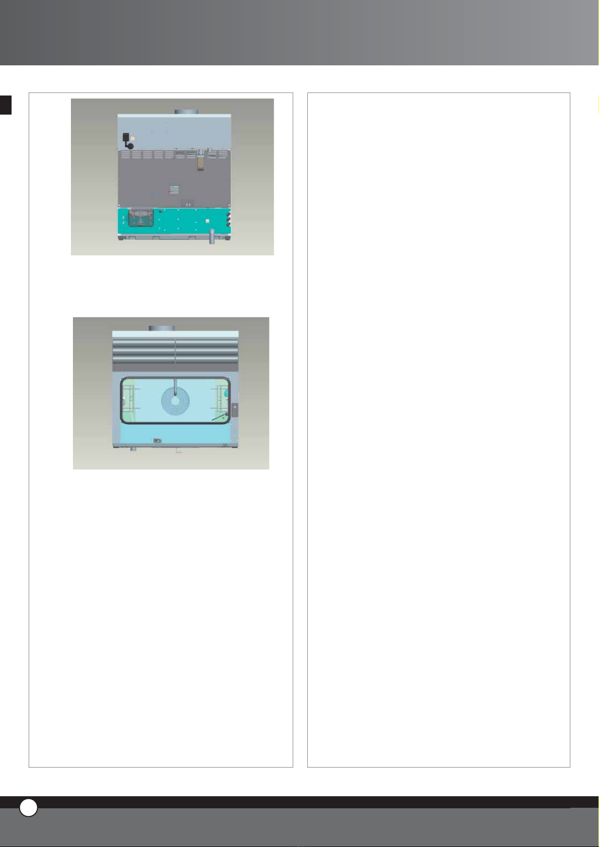
6. OVENS EXHAUSTS CONNECTION
The extract outlet of the oven has to be connected to
the proper inlet that is positioned on the rear of the hood
(see the picture). The second fumes inlet of the hood, if it
not used, has to be closed with the tap supplied.
If you need to connect two ovens to the hood, the ex-
tract exhaust of both of the ovens has to be connected to
the corresponding fumes inlet of the hood.
7. FUMES EXHAUST
The exhaust fumes of the hood are discharged from the
top of the hood through a tube of 151 mm of diameter.
ENGLISH
7
ENGLISH
UNO
X
R
6
ENGLISH
8. CONNECTION TO THE OVEN
The hood XC314 is connected to the oven through the
issued cable RJ45.
To connect the cable of the hood to the oven proceed as
follows:
remove the safety cap by unscrewing the proper
screw
Insert the connector of the cable in any one of the
three female connectors you find on the power card
(you can use any of them)
Re-assemble the safety cap by fixing the screw
Now the hood is recognized by the oven and connected
to it.
In case there are two ovens to be connected to the hood,
you can choose any of the ovens to connect directly to
the hood.
•
•
•
C. CERTIFICATION
Producer: UNOX S.p.A.
Address: Via Dell’Artigianato 28/30
I-35010 Vigodarzere, Padova, Italy
Product: Cooking fumes aspirating hood with
condensing system
Family: ChefTop™
Model: XC314
REFERENCE LAWS
The “CE” marking on the appliances indicated in this
manual refers to following UE directives:
ASPIRATING CONDENSING HOOD - SERIE XC:
Low Voltage Directive 2006/95/CE following the rules:
EN 60335-2-42+A1
EN 60335-2-46+A1
EN 50366:2003
Electromagnetic Compatibility Directive 2004/108/CE
following the rules:
EN 55014-1:2000; A1; A2
EN 55014-2:1997; A1
EN 61000-3-2:2000
EN 61000-3-3:1995; A1
TESTING AND CERTIFICATION INSTITUTE:
NEMKO S.p.a.
Via del Carroccio
I-20046 Biassono, Milano, Italy
Luogo: Vigodarzere, Padova, Italy
Data: 12/02/2007
•
•
•
•
•
•
•
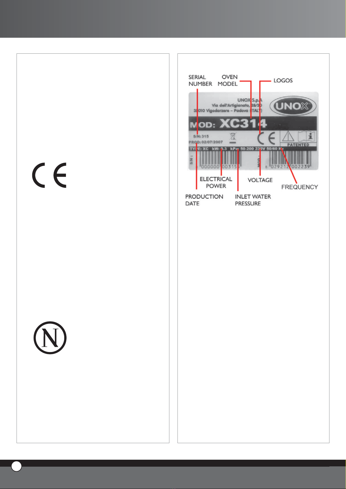
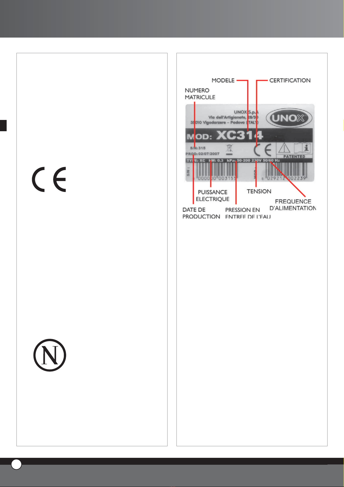
DATA PLATE
7ENGLISH
ChefTop™
UNO
X
R
8
ENGLISH

ChefTop™
Indice:
A. INSTRUCTIONS POUR
L’UTILISATEUR page 02
1. AVERTISSEMENTS page 02
2. NETTOYAGE HOTTE page 02
2.1 Nettoyage externe Hotte
2.2 Nettoyage des filtres
3. FONCTIONNEMENT DE LA HOTTE page 02
4. MAINTENANCE ORDINAIRE page 02
5. MAINTENANCE EXTRAORDINAIRE page 02
6. COUPURE EN CAS DE PANNE page 02
7. LES PANNES PLUS FRÉQUENTES page 03
8. MESSAGES D’ERREURS HOTTE page 03
B. INSTRUCTIONS POUR
L’INSTALLATEUR page 04
1. AVERTISSEMENTS page 04
2. OPÉRATIONS PRÉLIMINAIRES page 04
2.1 Lieu d’Installation
2.2 Enlèvement De La Pellicule De Protection
2.3 Positionnement
3. BRANCHEMENT ELECTRIQUE page 05
3.1 Avertissements
3.2 Branchement Au Réseau D’alimentation
Electrique
3.3 Branchement Equipotentiel
4. RACCORDEMENT HYDRIQUE page 05
4.1 Avertissements
5. RACCORDEMENT EVACUATIONS page 05
5.1 Evacuation de l’Eau
6. LIAISON CHEMINEES DES FOURS page 06
7. SORTIE FUMEES
8. LIAISION AU FOUR page 06
C. CERTIFICATIONS page 07
INTRODUCTION
Gentil Client; Merci et Compliments pour avoir acheté
un four de la ligne ChefTop™. On souhaite que ce soit le
début d’une collaboration positive de longue durée.
Comme vous savez, la ligne des fours ChefTop™ et tous
ses équipements complémentaires (cellule de refroidisse-
ment rapide, cellule de maintien en température, plaques
et grilles spéciales) ont été étudiés pour vous permettre
de compléter n’importe quel processus de cuisson que
soit simple ou compliqué.
L’innovant panneau de commandes ChefTouch vous
permettra de commander, à l’aide d’un seul contrôle,
tous les équipements UNOX liés au four.
De toute façon, c’est toujours vous le Chef plus important!
1FRANÇAIS
ChefTop™
UNO
X
R
2
FRANÇAIS
A. ISTRUCTIONSPOURL’UTI-
LISATEUR
1. AVERTISSEMENTS
ATTENTION: Prière de lire attentivement ce manuel
d’instructions qui vous fournit des indications importantes
concernant la sécurité et l’emploi de l’équipement.
Conserver avec précaution ce manuel pour toutes les ul-
térieures consultations des différents opérateurs.
L’équipement doit être destiné uniquement à l’emploi
pour lequel il a été expressément conçu; des autres emp-
lois sont retenus abusifs.
La hotte XC314 a été conçue pour aspirer et condenser
les fumées qui sortent de la cheminée de cuisson du four
et pour aspirer et expulser les fumées qui sortent de la
porte du four quand on l’ouvre.
La hotte XC314 peut fonctionner seulement si reliée aux
fours de la série ChefTop™ modèles XVC104, XVC304,
XVC504, XVC704.
En phase de première utilisation, faire attention que le no-
tice d’utilisation, des sacs en plastic ou n’importe quel au-
tre objet, ne soient pas présents à l’intérieur de la hotte.
L’équipement est destiné uniquement à l’emploi profession-
nel spécifique et doit être utilisé par un personnel qualifié.
Eviter de positionner des fontes de chaleur à côté de
l’équipement.
Utiliser la hotte avec une température ambiante com-
prise entre +5 °C e +35 °C.
Les interventions d’installation, de maintenance et de
réparation doivent être exécutées seulement pas un per-
sonnel qualifié et convenablement formé. Avant de faire
ces interventions, débrancher la tension d’alimentation
de l’équipement.
Au cas où l’équipement serait positionné sur un support
dotés de roues, faites attention que le mouvement con-
senti n’endommage pas des câbles électriques, des tuyau-
teries de l’eau, des tuyauteries d’évacuation ou n’importe
quel type de raccordements.
2. NETTOYAGE HOTTE
AVERTISSEMENT:
Avant d’effectuer n’importe quelle intervention de main-
tenance ou de nettoyage, il est nécessaire débrancher
l’alimentation électrique et attendre le refroidissement
de l’appareil.
2.1 NETTOYAGE EXTERNE HOTTE
Ne jamais utiliser un jet d’eau en pression pour le lavage
externe de la hotte.
Utiliser seulement des tissus humides.
2.2 NETTOYAGE DES FILTRES
Les filtres sont mis dans la partie antérieure de la hotte.
Ils sont emboîtables.
Les filtres doivent être laver périodiquement dans une
lave-vaisselle.
3. FONCTIONNEMENT DE LA HOTTE
Le fonctionnement de la hotte est complètement au-
tomatique: quand on fait partir un cycle de cuisson (en
modalité manuelle ou programmée) la hotte fonctionne
lentement (elle aspire à ce point les fumées qui sortent de
la cheminée du four) ; quand on ouvre la porte du four, la
hotte fonctionne à grande vitesse (elle aspire à ce point
les fumées qui sortent de la porte du four).
Quand la hotte ressent la présence des fumées chaudes
en sortie de la cheminée du four, elle fait partir en au-
tomatique le système de condensation.
Sur la hotte, aucune commande n’est présente.
4. MAINTENANCE ORDINAIRE
Toutes les opérations de maintenance doivent être effec-
tuées uniquement par un personnel d’entretien qualifié.
Avant d’effectuer n’importe quel type de maintenance,
il faut débrancher l’alimentation électrique et attendre le
refroidissement de l’équipement.
Il faut soumettre l’équipement périodiquement (au moins
une fois par an) à un contrôle total de la part d’un tech-
nicien spécialisé.
5. MAINTENANCE EXTRAORDINAIRE
Toutes les opérations de maintenance doivent être effec-
tuées uniquement par un personnel d’entretien qualifié.
Avant d’effectuer n’importe quel type de maintenance,
il faut débrancher l’alimentation électrique et attendre le
refroidissement de l’équipement.
Les composantes qui nécessitent la maintenance, sont ac-
cessibles en enlevant le panneau postérieur de la hotte.
6. COUPURE EN CAS DE PANNE
En cas de panne, désactiver l’équipement :
débrancher l’interrupteur automatique d’alimentation
électrique qui alimente l’appareil.
s’adresser au centre d’assistance technique Unox plus
proche
•
•

ChefTop™
3FRANÇAIS
ChefTop™
7. LES PANNES PLUS FRÉQUENTES
BREAKDOWN CAUSE SOLUTION
The hood is not connected to the
power mains
Connect the hood to the supply
mains
The hood is not connected to the
oven Connect the hood to the oven
Interrupted or damaged oven-
hood connecting cable
Apply to a qualified UNOX
technician for service
Damaged hood motor Apply to a qualified UNOX
technician for service
Damaged motor starting
condenser
Apply to a qualified UNOX
technician for service
Damaged hood power card Apply to a qualified UNOX
technician for service
Damaged oven control board Apply to a qualified UNOX
technician for service
When a cooking program starts,
the hood does not work
Damaged oven power card Apply to a qualified UNOX
technician for service
Interrupted or damaged oven-
hood connecting cable
Apply to a qualified UNOX
technician for service
Damaged hood motor Apply to a qualified UNOX
technician for service
Damaged hood power card Apply to a qualified UNOX
technician for service
Damaged oven control board Apply to a qualified UNOX
technician for service
Damaged oven power card Apply to a qualified UNOX
technician for service
When you open the door of the
oven, the hood motor does not
pass to high speed
Damaged oven door switch Apply to a qualified UNOX
technician for service
Closed water inlet Open water inlet
Not correct connection to the
water supply
Check the connection to the
water supply
Dirty water inlet filter Clean the filter
Damaged water solenoid valve Apply to a qualified UNOX
technician for service
Damaged temperature probe Apply to a qualified UNOX
technician for service
Fumes condensating system does
not work
Damaged hood power card Apply to a qualified UNOX
technician for service
8. MESSAGES D’ERREURS HOTTE
BREAKDOWN CAUSE SOLUTION
The connection wires of the
temperature probe 1 are
disconnected from the power
card
Apply to a qualified UNOX
technician for service
Damaged temperature probe Apply to a qualified UNOX
technician for service
The display panel 1 shows the
message EC1 continuously.
Damaged hood power card Apply to a qualified UNOX
technician for service
B. INSTRUCTIONS POUR L’INSTALLATEUR

UNO
X
R
4
FRANÇAIS
1. AVERTISSEMENTS
Touteslesopérationsd’installation,demontage,d’assistance
et de maintenance doivent être faites par un personnel
techniquement qualifié selon les normes en vigueur.
Prière de lire attentivement le notice d’utilisation avant
l’installation et la mise en service de l’appareil.
Prière de vérifier l’intégrité de l’appareil (contrôler les
éventuels dommages de transport). Enlever de l’intérieur
de la hotte tout le matériel informatif.
2. OPÉRATIONS PRÉLIMINAIRES
2.1 LIEU D’INSTALLATION
Avant de positionner l’appareil, vérifier les mesures
d’encombrement et l’exacte position des branchements
et des raccordements électriques, hydriques, évacuation
fumées selon les figures rapportées dans l’annexe, chapi-
tre “Données techniques”.
2.2
ENLÈVEMENT DE LA PELLICULE DE PROTECTION
Enlever attentivement et complètement la pellicule de
protection qui couvre les parties externes de l’appareil
en évitant de laisser des résidus de colle.
Si malgré ça ces résidus persistent, il faut les enlever avec
un solvant convenable.
2.3 POSITIONNEMENT
Positionner l’appareil en respectant les normes de sécu-
rité indiquées comme suit:
Positionner l’appareil en mode que les parties postérieures
soient facilement accessibles pour effectuer le branchement
électrique et pour permettre la maintenance de l’appareil.
L’appareil n’est pas encastrable parmi des autres appar-
eils.
Si l’appareil est positionné à côté d’un mur, diviseurs,
meubles de cuisine, bordures décorées etc., on vous re-
commande que ceux-ci soient faites d’un matériel incom-
bustible.
En cas contraire ils doivent être revêtus par un matériel
isolant thermique incombustible, et il faut prêter une
grande attention aux règles de prévention incendies.
Ne pas installer l’appareil dans les proximités d’une fri-
teuse.
La hotte doit être positionnée au-dessus du four et fixée
au celui-ci par les vis prévues à cet effet.
Sur la partie postérieure, on utilise les vis de fixage du
dot de four.

ChefTop™
5FRANÇAIS
ChefTop™
Sur la partie antérieure, on utilise les vis autotaradeuses
et autoperceuses destinées à cet usage (les vis sont fourn-
ies en dotation avec la hotte).
3. BRANCHEMENT ELECTRIQUE
3.1 AVERTISSEMENTS
Le branchement au réseau électrique doit être effectué
selon les normatives en vigueur.
Avant d’effectuer le branchement, contrôler que la ten-
sion et la fréquence correspondent aux données présen-
tent sur l’étiquette posée sur l’appareil.
L’appareil doit être positionné de sorte que la fiche de
connexion au réseau, soit accessible.
Interposer entre l’appareil et le réseau, un interrupteur om-
nipolaire accessible après l’installation, ayant des contacts
avec une distance d’ouverture minimum de 3 mm, de portée
appropriée (par ex. :interrupteur magnétothermique).
On vous conseille l’emploi d’un interrupteur de sécurité
pour panne de réseau.
La tension d’alimentation, lorsque l’appareil est en fonc-
tion, ne doit pas s’écarter de la valeur nominale de la
tension rapportée sur l’étiquette données du four, de
±10%.
3.2 BRANCHEMENT AU RESEAU D’ALIMENTATION
ELECTRIQUE
C’est suffisant insérer la fiche dans la prise appropriée (la
prise doit être indiquée pour la fiche fournie en dotation).
La substitution du câble doit être effectuée par un per-
sonnel autorisé.
L’appareil doit être branché à la ligne de terre du réseau.
3.3 BRANCHEMENT EQUIPOTENTIEL
L’appareil doit être inclus dans un système équipotentiel
d’une efficacité opportunément vérifiée selon les nor-
matives en vigueur. Ce branchement doit être effectuer
entre des différents équipements avec la borne ayant le
symbole:
Il Le conducteur équipotentiel doit avoir une section min-
imum de 10 mm².
4. RACCORDEMENT HYDRIQUE
4.1 AVERTISSEMENTS
Il est nécessaire d’interposer entre le réseau hydrique et
le four un robinet d’interception et un
filtre mécanique.
L’appareil est fourni avec 2 mètres de tube et son raccord
relatif (3/4”) avec un clapet de non-retour et un filtre mé-
canique comme les normes en vigueur exigent.
Avant de relier le tube d’eau à l’appareil, faire découler de
l’eau pour éliminer les éventuels résidus.
L’eau en entrée doit avoir une valeur de pression comprise
entre 2 et 8 bar et une température maximum de 30°C.
5. RACCORDEMENT EVACUATIONS
5.1 EVACUATION DE L’EAU
Le tube d’évacuation de l’eau de condensation se trouve
dans la partie postérieure de la hotte et doit être reliée
avec un tuyau rigide ou flexible et acheminé vers une vi-

UNO
X
R
6
FRANÇAIS
dange ouverte ou à siphon;
son diamètre ne doit pas être inférieur à celui de l’embout
de vidange et sa longueur ne doit pas être supérieure à un
mètre . Le tuyau doit être enfermé en utilisant un collier
serre-tube métallique de façon que le même tuyau ne se
désenfile pas de la vidange.
Evitez les rétrécissements sur les conduits flexibles ou sur
les coudes des conduites métalliques tout au long du par-
cours de vidange.
6. COLLEGAMENTO CAMINI FORNI
Il camino uscita fumi del forno va collegato all’apposito
ingresso posto nella parte posteriore della cappa (vedere
figura). L’altro ingresso fumi della cappa, se non utilizzato,
va chiuso con l’apposito tappo in dotazione.
La cheminée sortie fumées du four doit être reliée à
l’entrée convenable posée sur la partie postérieure de la
hotte (voir figure). L’autre entrée fumées de la hotte, si
on ne l’utilise pas, doit être fermée par l’approprié bou-
chon en dotation de la hotte.
S’il y a deux fours, la sortie fumées de claque four doit
être reliée à l’entrée fumées correspondante de la hotte.
7. SORTIE FUMEES
Les fumées en sortie de la hotte, sortent de la partie
supérieure de la hotte à travers un tube ayant un diamè-
tre de 151 mm.
8. BRANCHEMENT AU FOUR
La hotte XC314 doit être reliée au four à l’aide du câble
RJ45 en dotation.
Pour relier le câble de la hotte au four, procéder comme suit:
Enlever le couvercle de protection en dévissant la vis
Insérer le connecteur du câble dans le convenable
connecteur femelle présent sur la fiche de puissance
(aucune importance pour quel connecteur des 3
présents vous utilisez)
Remonter le couvercle de protection en serrant la vis
De cette façon la hotte est bien identifiée et reliée au four.
Au cas où la hotte est reliée à deux fours, le branche-
ment peut être fait, sans aucune différence, à un des deux
fours.
•
•
•
ChefTop™
C. CERTIFICATIONS
Constructeur: UNOX S.p.A.
Adresse: Via Dell’Artigianato 28/30
I-35010 Vigodarzere, Padova, Italy
Produit: Hotte d’aspiration vapeurs de cuisson
avec système de condensation
Famille: ChefTop™
Modèle: XC314
NORMATIVES DE REFERENCE
Le marquage “CE” reporté sur les équipements insérés
dans ce Manuel a comme référence les suivantes direc-
tives:
HOTTE D’ASPIRATION AVEC CONDENSEUR DE
VAPEURS - SERIE XC:
Directive Basse Tension 2006/95/CE selon les normes:
EN 60335-2-42+A1
EN 60335-2-46+A1
EN 50366:2003
Directive Compatibilité Électromagnétique 2004/108/CE
selon les normes:
EN 55014-1:2000; A1; A2
EN 55014-2:1997; A1
EN 61000-3-2:2000
EN 61000-3-3:1995; A1
INSTITUT DE CONTRÔLE ET CERTIFICATIONS:
NEMKO S.p.a.
Via del Carroccio
I-20046 Biassono, Milano, Italy
Lieu: Vigodarzere, Padova, Italy
Date: 12/02/2007
•
•
•
•
•
•
•
PLAQUE SIGNALETIQUE
7FRANÇAIS
ChefTop™

UNO
X
R
8
FRANÇAIS

ChefTop™
EINLEITUNG
Lieber Kunde, wir möchten Ihnen zu dem Erwerb eines
ChefTop™ Ofens gratulieren und danken. Wir hoffen
dies wird der Anfang einer guten Zusammenarbeit.
Wie Sie sicher wissen, wurde die ChefTop™ Serie mit
ihrer gesamten Ausstattung entwickelt, um Ihnen das Ko-
chen von einfachen bis zu komplizierten Kochprozessen
zu ermöglichen.
Durch die überragende Entwicklung der ChefTouch Be-
dienoberfläche können Sie alle an den Ofen angeschlos-
senen Geräte einfach kontrollieren.
Aber der wichtigste Koch sind immer noch Sie!
13 ENGLISH
1DEUTSCH
Inhaltsverzeichniss:
A. ANLEITUNG FÜR DEN BENUTZER seite 2
2. REINIGUNG DES WASCHSYSTEMS seite 2
2.1 Hinweis
2.2 Äußere Reinigung
3. FUNKTION DES WASCHSYSTEMS seite 2
4. INSTANDHALTUNG seite 3
5. WARTUNG seite 3
6. AUSSCHALTEN BEI
FUNKTIONSSTÖRUNGEN seite 3
7. FUNKTIONSSTÖRUNGEN,
PROBLEMURSACHEN UND
PROBLEMBEHEBUNG seite 4
B. ANLEITUNG FÜR DEN
INSTALLATEUR seite 5
1. EINFÜHRUNG seite 5
2. INSTALLATIONSVORBEREITUNGEN seite 5
2.1 PRÜFUNG VOR DER INSTALLATION
2.2 ENTFERNEN DER SCHUTZFOLIE
3. Montage der Edelstahlmischbox seite 6
4. WASSERANSCHLUSS seite 6
5. Montage des Wascharmes seite 6
6. Reiniger und Klarspüler seite 6
C. ZERTIFIKATION seite 7
REINIGER UND KLARSPÜLER seite 8
ChefTop™

A. ANLEITUNG FÜR DEN
BENUTZER
1. Hinweis
Achtung: Lesen Sie bitte vor dem Gebrauch, die Bedi-
enungsanleitung gründlich durch. Bewahren Sie die Bedi-
enungsanleitung bitte sehr sorgfältig auf.
Nutzen Sie das Gerät nur für die vorgesehenen Zwecke.
Die Kondensationshaube XC314 ist konstruiert worden,
um den Dampf der aus dem Kamin des Ofens ständig
austritt abzuziehen und über den Dampfkondensator zu
löschen.
Bei geöffneter Ofentür wird vorne ebenfalls der Dampf
abgezogen allerdings nicht abgelöscht.
Die Haube XC314 passt nur zu der ChefTop™ Serie,
Modelle XVC104, XVC304, XVC504, XVC704.
Vor der ersten Inbetriebnahme des Gerätes vergewissern
Sie sich bitte, dass innerhalb der Haube kein Unterlagen
oder Plastiktüten liegen.
Das Gerät sollte nur von qualifizierten Personal bedient
werden um Fehlerquellen vorzubeugen.
Installieren Sie das Gerät nie in der Nähe von Hitzequellen
wie Herdplatten.
Der Haube sollte nur bei einer Raumtemperatur
von +5 bis +35°C genutzt werden.
Reparaturen und Installationsarbeiten müssen von ges-
chultem Personal durchgeführt werden. Bevor diese Ar-
beiten durchgeführt werden sollte der Stromverbindung
getrennt werden.
Falls die Haube incl. des Ofens auf einem mobilem Un-
terbau installiert werden, muss darauf geachtet werden,
dass das Kabel sowie die Schläuche beim verschieben des
Gerätes nicht beschädigt oder eingeknickt werden kön-
nen. In diesem Fall sollten die Kabel so fixiert werden,
dass diese nicht ausgerissen werden.
2. REINIGUNG DER HAUBE
Hinweis: Vor dem Reinigen des Gerätes, nehmen Sie bitte
die Stromzufuhr aus der Steckdose and
lassen Sie das Gerät abkühlen.
14
ENGLISH
UNO
X
R
2
DEUTSCH
2.1 Äußere Reinigung
Nutzen Sie niemals Hochdruckreiniger. Es genügt wenn
das Gerät mit einem feuchten Tuch abgewischt wird.
2.2 Reinigung der Filter
Die beiden Filter finden Sie im vorderen Bereich der
Haube.
Die Filter sollten regelmäßig in der Spülmaschine gerein-
igt werden.
3. Funktion der Haube
Die Haube funktioniert vollautomatisch: sobald ein Ko-
chprogramm gestartet wird (egal ob manuell eingestellte
Programme oder gespeicherte Programme) läuft die
Haube bei niedrigen Umdrehungen
( Abzug des aus dem Ofenabluftrohr austretenden Damp-
fes); sobald die Ofentür geöffnet wird, läuft die Haube bei
maximaler Umdrehungszahl ( auch der Dampf der vorne
austritt, wird abgezogen).
Über Sensoren innerhalb der Haube wird das Kondensa-
tionssystem angesteuert.
4. INSTANDHALTUNG
Wartungen sollten ausschließlich von einem Techniker
durchgeführt werden. Trennen Sie für Wartungen das
Gerät von der Stromverbindung und lassen Sie es abküh-
len.
Schrauben Sie die Rückwand ab um Zugriff auf alle
Anschlüsse zu haben.
5. WARTUNG
Wartungen sollten ausschließlich von einem Techniker
durchgeführt werden. Trennen Sie für Wartungen das
Gerät von der Stromverbindung und lassen Sie es abküh-
len.
Schrauben Sie die Rückwand ab um Zugriff auf alle
Anschlüsse zu haben.
6. AUSSCHALTEN BEI FUNKTIONSSTÖRUNGEN
Bei Funktionsstörungen des Gerätes ist folgendes zu tun:
Trennen Sie das Gerät von der Stromversorgung
Kontaktieren Sie den UNOX Kundendienst
•
•

ChefTop™
13 ENGLISH
3DEUTSCH
ChefTop™
7. FUNKTIONSSTÖRUNGEN, PROBLEMURSACHEN UND PROBLEMBEHEBUNG
Problem Ursache Lösung
Die Hauptversorgungsspannung fehlt Stellen Sie die
Hauptversorgungsspannung wieder her
Die Haube ist mit dem Gerät
nicht verbunden
Verbinden Sie die Haube mit dem
Kombidämpfer
Defekt am Verbindungskabel Wenden Sie sich an einen UNOX
Techniker
Motor der Haube ist defekt Wenden Sie sich an einen UNOX
Techniker
Anlaufkondensator von dem
Motor ist defekt
Wenden Sie sich an einen UNOX
Techniker
Powerplatine von der Haube ist
defekt
Wenden Sie sich an einen UNOX
Techniker
Defekte Powerplatine des
Kombidämpfers
Wenden Sie sich an einen UNOX
Techniker
Kochprogramm läuft, aber die
Haube
funktioniert nicht
Defekte Bedienplatine des
Kombidämpfers
Wenden Sie sich an einen UNOX
Techniker
Defekt am Verbindungskabel Wenden Sie sich an einen UNOX
Techniker
Motor der Haube ist defekt Wenden Sie sich an einen UNOX
Techniker
Defekte Powerplatine bei der
Haube
Wenden Sie sich an einen UNOX
Techniker
Defekte Bedienplatine des
Kombidämpfers
Wenden Sie sich an einen UNOX
Techniker
Defekte Powerplatine des
Kombidämpfers
Wenden Sie sich an einen UNOX
Techniker
Beim Öffnen der Gerätetür
läuft der Motor weiterhin bei
niedrigen Umdrehungen
Türkontaktschalter ist defekt Wenden Sie sich an einen UNOX
Techniker
Der Wasserzulauf ist nicht
hergestellt Wasserzulauf herstellen
Die Wasserverbindung ist nicht
richtig hergestellt
Überprüfen Sie die
Wasserverbindung
Verschmutzter
Wassermagnetventil
Säubern Sie das Ventil
Magnetventil defekt Wenden Sie sich an einen UNOX
Techniker
Thermostat defekt Wenden Sie sich an einen UNOX
Techniker
Kondensationssystem funktioniert
nicht
Defekte Powerplatine bei der
Haube
Wenden Sie sich an einen UNOX
Techniker
8. FEHLERMELDUNGEN
Problem Ursache Lösung
Der Temperaturfühler hat sich von der
Powerplatine gelöst Wenden Sie sich an einen UNOX
Techniker
Defekter Temperaturfühler Wenden Sie sich an einen UNOX
Techniker
Im Display wird die Meldung
EC1 angezeigt
Defekt an der Powerplatine von
der Haube
Wenden Sie sich an einen UNOX
Techniker
Table of contents
Languages:
Other Unox Ventilation Hood manuals


