Unox XC595 Instruction manual

ENGLISH
FRANÇAIS
DEUTSCH
ITALIANO
ESPANOL
INSTRUCTION MANUAL AND
TECHNICAL DATAS
MANUEL DES INSTRUCTIONS
ET DES DONNÉES TECHNIQUES
BEDIENUNGSANWEISUNG
MANUALE DI ISTRUZIONI
E DATI TECNICI
MANUAL ISTRUCIONES Y
DATOS TECNOCOS
UNO
R
07-2005
LineMiss
LineMissTM
Hood - Hotte - Gärschränke - Cappa - Campana
XC595
XC535

UNO
R
UNO
R
Index:
I. Instructions for the installer
1. DATA PLATE
2. CERTIFICATION
3. Installation
- 3.1 PRELIMINARY OPERATIONS
- 3.2 POSITIONING
- 3.3 REMOVAL OF THE
PROTECTIVE FILM
4. Installation
4.1- ELETTRICAL CONNECTION
4.2- CONNECTION TO THE OVEN
4.3- WATER CONNECTION
II. Instructions for the user
1. INSTRUCTIONS FOE THE
OPERATOR
2. NOTES FOR THE USE
3. HOOD OPERATION
4. CLEANING OF THE HOOD
5. TURNING OFF IN
CASE OF BREAKDOWN
IV. Maintenance
1. ORDINARY MAINTENANCE
2. SPECIAL MAINTENANCE
3. MORE FRQUENT BREAKDOWNS
ENGLISH
ENGLISH
ENGLISH
2
page 3
page 3
page 3
page 3
page 4
page 6
page 6
page 6
page 6
page 6
page 6
page 7
page 7
page 7
page 7
page 8
UNO
R
UNO
R
I.
INSTRUCTIONS FOR THE
INSTALLER
Dear customer, we would like to thank you
and congratulate you on the purchase of
one of
UNOX
products. The instructions and
suggestions that follow concern the phases of
a proper installation, as well as the use and
maintenance for your safety and for the best use
of the appliance.
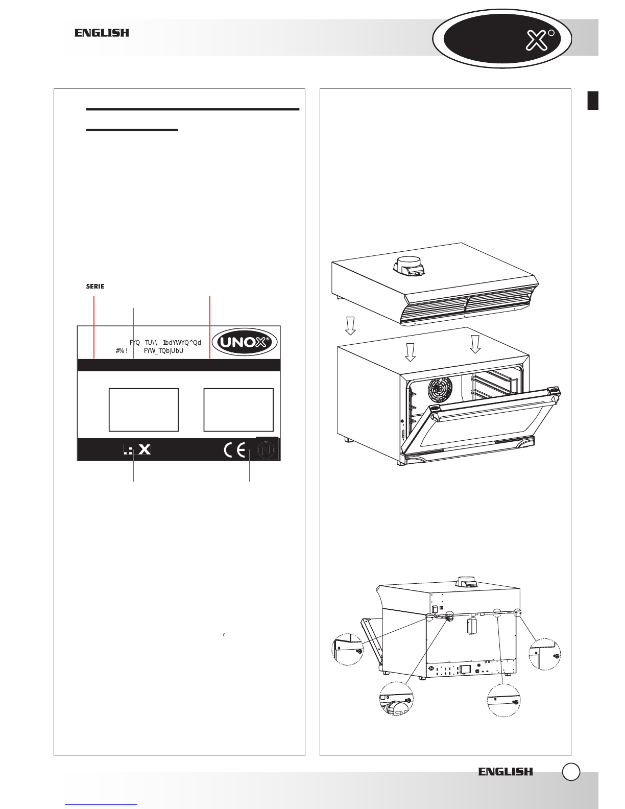
1.
DATA PLATE
2.
CERTIFICATION
The “CE” brand you find on our labels and on our
user manual refers to the following directives:
HOOS STEAM CONDENSER - mod. XC535 XC595 :
- Low Tension Directive
DBT 73/23/CEE & 93/68/CEE,
according to rule EN60335-2-42+A1 &
according to rule EN60335-2-46+A1
- Electromagnetic Compatibility Directive
,
according to rules EN60555-3, EN55014 & EN55104.
3.
INSTALLATION
- PRELIMINARY OPERATIONS
All the electrical connections and installations must
be done by qualified personnel according to actual
laws.
3.1
CHECK THE INSTALLATION LOCATION
Before placing the appliance, please verify the overall
measurements and the exact position of the electrical
connections looking at the pictures on the attached
file “TECHNICAL DATA”.
3.2 POSITIONING
The hood has to be placed upon the oven and fixed to
the oven by the appropriate screws.
In the back side, you use the fixing screws of the
oven’s back.
ENGLISH
ENGLISH
ENGLISH
3
UNOX S.p.A.
FYQTU\\1bdYWYQ^Qd_"(#
#% ! FYW_TQbjUbU@49D
1<I
MOD
.: X
C595
DATE
TYPE: kW: POWER: FREQUENCY:
MOD: S/N
SERIE
FYQTU\\1bdYWYQ^Qd_"(#
#% ! FYW_TQbjUbU@49D
TENSION D'ALIMENTACION
.: X
MODELE DU FOUR
CERTIFICATIONS
PUISSANCE ELECTRONIC
UNO
R
UNO
R
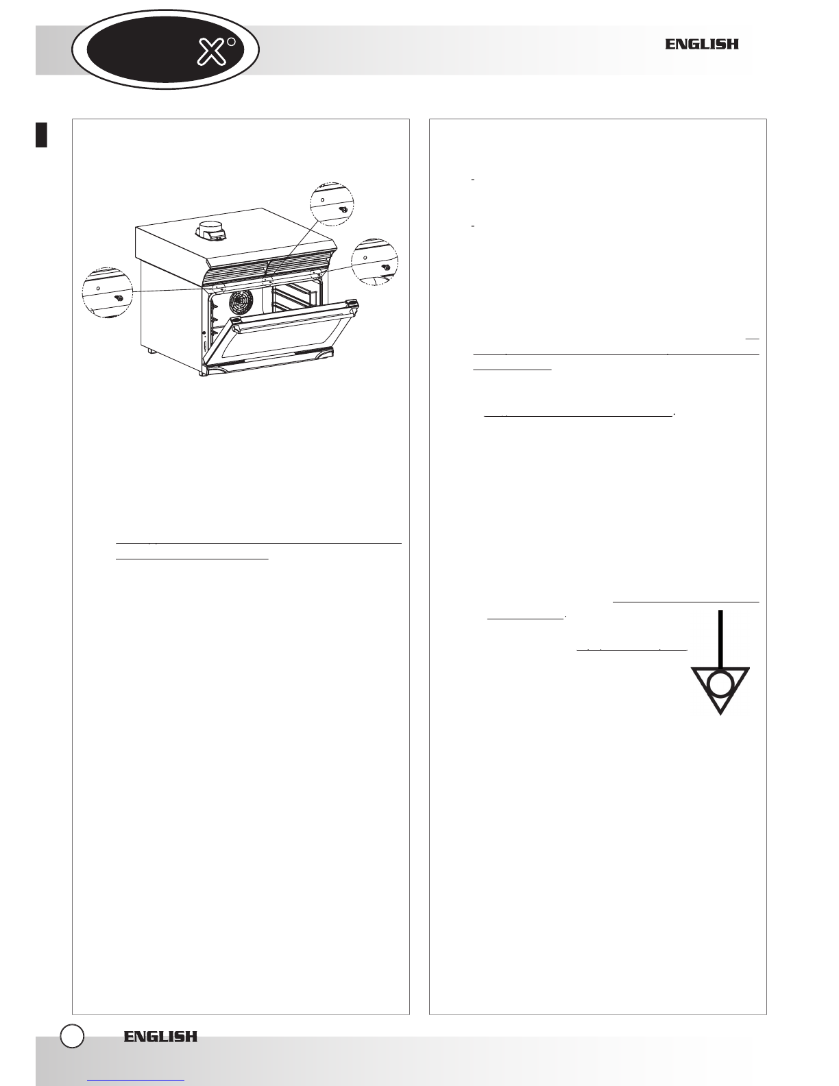
In the front, you use the appropriate auto-drilling
screws ( supplied with the hood ).
Place the appliance respecting the safety standards
in force that you find here following described.
Place the appliance so that its back and lateral sides
can be easily reached in order to make the electrical
connections and provide the needed service.
The appliance is not suitable for built-in installation
The appliance is not suitable for built-in installation
and side by side positioning.
and side by side positioning.
If the appliance is placed near walls, dividers, kitchen
cabinets, decorated edges, etc., it is recommended
that this be of non combustible material.
Otherwise, they must be coated with non combustible
thermal insulating material and you must be very
respectful of the fire prevention standards.
3.3
REMOVAL OF THE PROTECTIVE FILM
Carefully remove all the protective film from the
external walls of the appliance. Pay attention not to
leave any rest of glue on the sides. If there should
be any residue, please remove it with an appropriate
solvent.
4.
INSTALLATION
4.1
ELETTRICAL CONNECTION
a-
The connection to the electrical power supply
system must be done according to the standard
in force.
The installer is responsible of the correct electrical
connection and of the compliance of the safety
standards.
Before connecting the appliance, make sure that :
-
the voltage and the frequency correspond to those
stated on the data plate of the appliance.
-
the outlet has the grounding and that is able to
support the charge requested by the appliance
indicated on its data plate.
-
the outlet fits the type of the plug installed on the
appliance (Schuko 16 A)
Avoid to use extensions and multiple outlets.
The appliance must be placed so that the connection
plug can be easily reached.
Place between the appliance and the network
an
omni-polar switch so that it is easily accessible after
omni-polar switch so that it is easily accessible after
the installation
. The contacts of this switch must have
a minimum opening distance of 3 mm and the switch
must have an appropriate input. We advise the use of
a
magneto-thermal differential switch
magneto-thermal differential switch
.
When the appliance is working the power supply
voltage must not diverge from the value of the
nominal voltage, written on the technical data plate,
by more than ± 10%.
The connection to the electrical power must be done
through a Schuko plug of 16 A.
Place the input cable in a way that no point exceeds
the environment’s temperature for more than 50°C.
b-
The appliance must be
connected to the round line
of the network
.
Moreover, the appliance must be
included in an
equipotential system
equipotential system
whose efficiency must be properly
checked according to the current
law.
This connection must be done
between the different appliances
using the terminal marked with the symbol:
The equipotential conductor must have a minimum
section of 10 mmq.
4.2
CONNECTION TO THE OVEN
To connect steam condenser to the oven, please
operate as follows:
a-
Electrical Connection
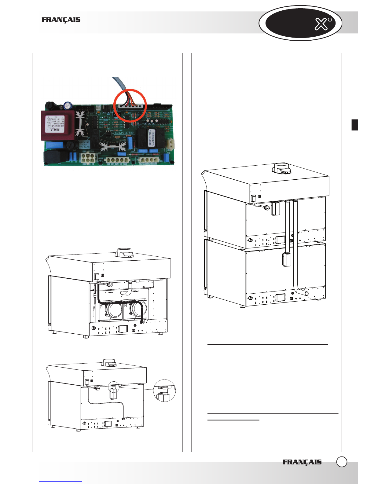
1-
Remove the back of the oven
2-
Connect the control cable of the hood to the power
board by connecting it to the proper connector (see
the picture)
3-
Fix the cable fastener your find on the cable of the
hood in the special slit you find on the bottom of the
ENGLISH
ENGLISH
ENGLISH
4

UNO
R
UNO
R
oven (see the picture)
4-
Reassemble the back of the oven
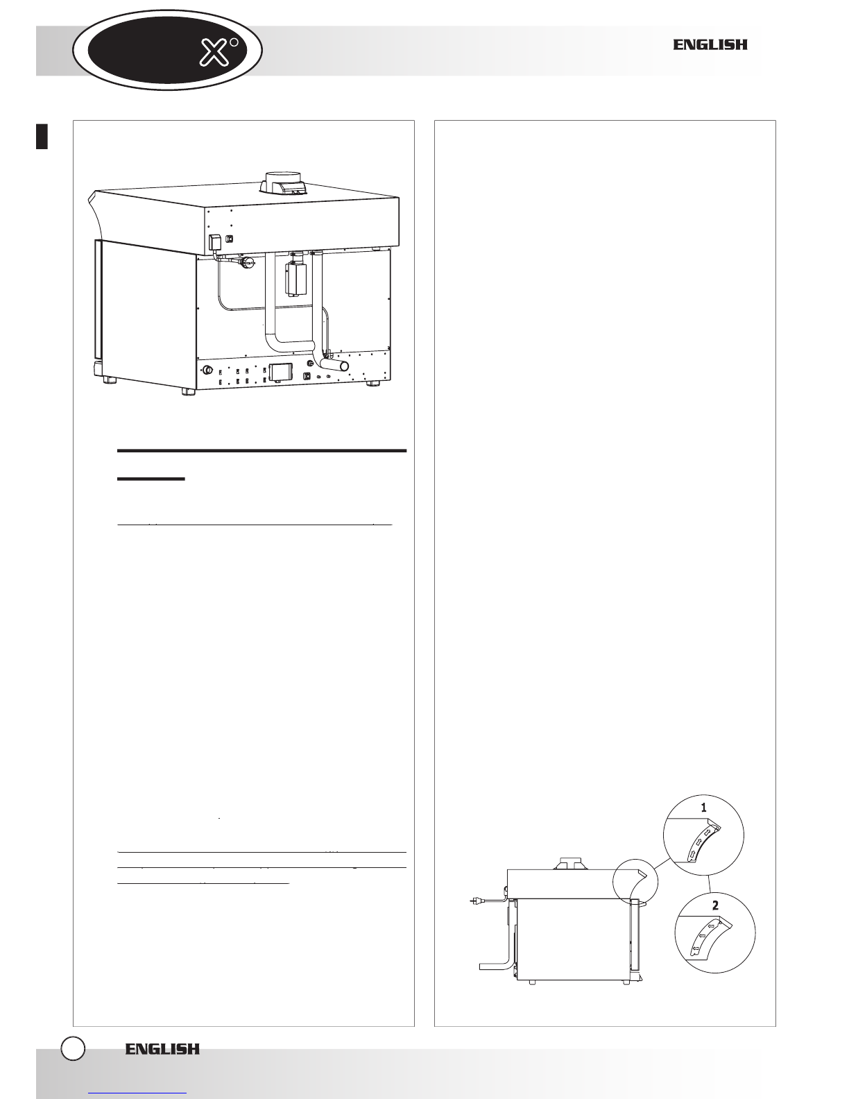
b-
it is necessary to connect the oven’s chimney to
the appropriate entry placed on the back side of
the hood by using the silicone tube supplied with
the hood. The silicone tube has to be tightened
to the oven’s chimney by using the metallic clamp
(supplied also with the hood).
In case the hood is connected to only one
oven, the smoke entry that remains free must be
connected to the condensate drainage system
tube.
CONNECTION SECOND OVEN
In equipment with the hood there’s a second oven-
hood connection cable : such a cable allows to
connect two ovens to same hood ( overlapped
ovens). The hood is indifferently controlled by the
first or the second oven. An extremity of the cable
goes connected to the hood’s control card (connector
HOOD/SC2 CN5) while the other extremity goes
connected to second oven.
The chimney of the second oven goes connected to
the appropriate entry in the back side of the hood (the
silicone tube in order to connect the second oven is
supplied in equipment with the overlap’s kit XC610).
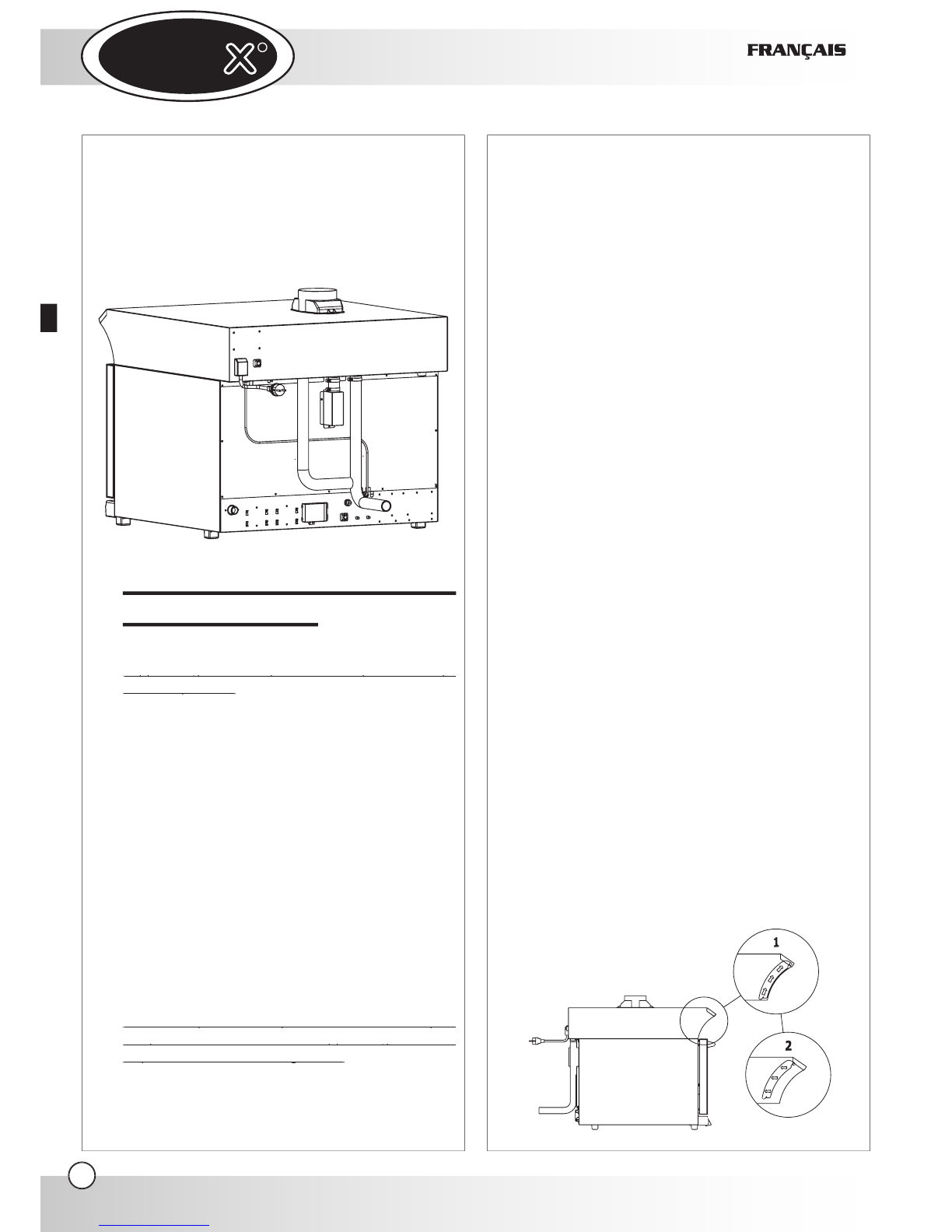
4.3
WATER CONNECTION
CONNECTION TO THE WATER SYSTEM
It is necessary to place between the water system and
the hood an interception plug cock and a mechanical
filter. Before connecting the water pipe to the hood,
please let a certain quantity of water flow to clean any
eventual remainder. The incoming water should have
a nominal pressure value included between 0.5 and
2 bars.
CONNECTION OF THE CONDENSATE
DRAINAGE SYSTEM
The condensate drainage system is located on the
back side of the hood and goes connected with a
rigid or flexible tube and piped to an open drainage;
its diameter shouldn’t be inferior to the one of the
drainage attack. Lock the tube by using the metallic
clamp so that the same tube does not extract from the
drainage.
Don’t throttle the flexible conduits & avoid elbows
ENGLISH
ENGLISH
ENGLISH
5
UNO
R
UNO
R
for the metallic conduits all along the distance of
drainage.
II.
INSTRUCTIONS FOR THE
USER
WARNING
:
The appliance cannot be cleaned with a water jet .
The appliance cannot be cleaned with a water jet .
The appliance is made for a specific professional use
and must be used by qualified personnel only.
1.
INSTRUCTIONS FOR THE OPERATOR
WARNING
:
carefully read this user manual before starting to
operate with the appliance as it gives you important
information regarding safety during installation, use
and maintenance of the appliance itself.
Keep the manual in a safe place where the different
operators that work with the appliance can easily find
and read it.
For any eventual repair, please apply only to
authorized service centres. Always require original
UNOX spare parts
.
Failure to observe the above suggestions can
Failure to observe the above suggestions can
compromise safety of the appliance and the guarantee
compromise safety of the appliance and the guarantee
cannot be recognized anymore.
cannot be recognized anymore.
2.
NOTES FOR THE USE
Premise:
This appliance must be used only in the way in which
it was expressly intended.
The hoods XC535 and XC595 has been planned in
order to suck and to condense the smoke coming out
from the oven’s chimney and in order to suck and
to expel the smoke coming out from the oven’s door
when we open it.
The hoods XC535 and XC595 can only work with
Unox Line Miss ovens supplied with the control
DYNAMIC.
Every other use is to be considered improper.
3. HOOD OPERATION
The hood operation is completely automatic: when
a cooking cycle is run (in manual or programmed
modality) the hood works in a low speed (the smoke
coming out from the oven’s chimney is sucked); when
the oven’s door is opened, the hood works in a high
speed (the smoke coming out from the oven’s door is
sucked )
When the hood perceives the presence of hot
smoke coming out from the oven’s chimney, it run
automatically the condensing system.
No command is present on the hood.
4.
PULIZIA CAPPA
WARNING:
Prima di effettuare qualsiasi intervento di
manutenzione o pulizia è necessario disinserire
l’alimentazione elettrica e aspettare il raffreddamento
dell’apparecchio.
4.1
CLEANING OF THE HOOD
Do not use a water jet in pressure to wash the external
part of the hood.
Use dampened clothes.
4.2
FILTERS CLEANING
The filters are placed on the front side of the hood.
They are fixed joint.
The filters should be washed periodically: the filters
cleaning should be done in a dish washer.
5.
TURNING OFF IN CASE OF BREAKDOWN
ENGLISH
ENGLISH
ENGLISH
6
UNO
R
UNO
R
In case of a breakdown, deactivate the appliance:
- disconnect the electrical power supply automatic
circuit breaker placed upstream from the
appliance.
- consult a technical service centre authorized by
the manufacturer where you can find trained
personnel
.
III.
MAINTENANCE
1.
ORDINARY MAINTENANCE
All maintenance operations must be done only by
qualified personnel.
Before starting any maintenance operation, you need
to disconnect the appliance from the electrical power
supply and wait for the appliance to cool down
.
The appliance must be regularly controlled (at least
once a year). A specialized technician has to control
the complete machine.
2. SPECIAL MAINTENANCE
All maintenance operations must be done only by
qualified personnel.
Before starting any maintenance operation, you need
to disconnect the appliance from the electrical power
supply and wait for the appliance to cool down
.
ENGLISH
ENGLISH
ENGLISH
7
UNO
R
UNO
R
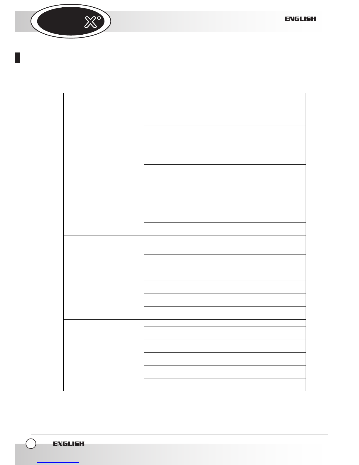
3. MORE FRQUENT BREAKDOWNS
ENGLISH
ENGLISH
ENGLISH
8
BREAKDOWN CAUSE SOLUTION
Hood not connected to the
electrical power system
Connect the hood to the
electrical power system
Hood not connected to the
oven Collegare la cappa al forno
The connection cable oven-
hood is disconnected or
damaged
Contact a specialized
technician for reparation
Hood’s motor damaged
Contact a specialized
technician for reparation
The Condenser of the motor
starting is damaged
Contact a specialized
technician for reparation
Hood’s control board damaged
Contact a specialized
technician for reparation
Ovens’ control board
Contact a specialized
technician for reparation
When a cooking cycle is
started, the hood's motor does
not work
Oven’s power board damaged Contact a specialized
technician for reparation
The connection cable oven-
hood is disconnected or
damaged
Contact a specialized
technician for reparation
Hood’s motor damaged Contact a specialized
technician for reparation
Hood’s control board damaged Contact a specialized
technician for reparation
Oven’s control board damaged Contact a specialized
technician for reparation
Oven’s power control damaged Contact a specialized
technician for reparation
When you open the oven's
door, the hood’s motor does
not go in high a speed
The switch of the oven’s door
is damaged
Contact a specialized
technician for reparation
The water inlet is closed Open water’s entry
The connection to the water
system is not correct
Verify the connection to the
water system
The filter of the water inlet is
closed by dirt Clean the filters
Water solenoid valve damaged Contact a specialized
technician for reparation
Damaged temperature probe Contact a specialized
technician for reparation
The water condensing system
is not working
Hood’s control board damaged Contact a specialized
technician for reparation
UNO
R
UNO
R
ENGLISH
ENGLISH
ENGLISH
9

UNO
R
UNO
R
Index:
I. Les Instructions pour l’installateur
1. PLAQUE SEGNALETIQUE
2. CERTIFICATION
3. L’Installation
3.1- LES OPERATIONS PRELIMINAIRES
3.2 - LE POSITIONNEMENT
3.3 - L’ENLEVEMENT DES
PELLICULES DE PROTECTION
4. L’Installation
4.1- CONNEXION ELECTRIQUE
4.2- CONNEXION AU FOUR
4.3- CONNEXION HYDRQUE
II. Les Instructions pou l’utilisateur
1. LES INSTRUCTIONS
POUR L’UTILISATEUR
2. INDICATIONS POUR L’EMPLOI
3. LE FONCTIONNEMENT DE LA HOTTE
4. LE NETTOYAGE DE LA HOTTE
5. ETEINGNEMENT EN CAS DE DEGÂT
IV. La Maintenance
1. MAINTENANCE ORDINAIRE
2. MAINTENANCE EXTRAORDINAIRE
3. LES DÉGÂTS PLUS FRÉQUENTS
FRANÇAIS
FRANÇAIS
FRANÇAIS
2
page 3
page 3
page 3
page 3
page 4
page 6
page 6
page 6
page 6
page 6
page 6
page 7
page 7
page 7
page 8

UNO
R
UNO
R
I.
LES INSTRUCTIONS POUR
L’INSTALLATEUR
Gentil Client, nous la remercions et nous nous
complimentons pour avoir acheté un produit UNOX.
Les avertissements et les conseils qui suivent concernent
les phases pour la correcte installation, l’usage et la
maintenance de l’équipement, pour sauvegarder sa
sûreté et pour une meilleure utilisation de l’appareil.
1.
PLAQUETTE SEGNALETIQUE
2.
CERTIFICATION
Le marquage «CE» rapportée sur les appareillages
insérés dans ce manuel fait référence aux suivantes
directives :
HOTTE CONDENSEUSE - réf. XC535 XC595 :
- Directive de la Basse Tension
DBT 73/23/CEE et 93/68/CEE,
selon la norme EN60335-2-42+A1 et
selon la norme EN60335-2-46+A1
- Directive de la Compatibilité Electromagnétique,
selon les normes EN60555-3, EN55014 et EN55104.
3.
L’INSTALLATION
- LES OPERATIONS PRELIMINAIRES
Toutes les opérations d’installation et de branchement
électrique doivent être faites par des personnes
qualifiées selon les normes en vigueur.
3.1
LA VÉRIFICATION DU LIEU D’INSTALLATION
Avant de positionner l’appareil vérifiez les mesures
d’encombrement et l’exacte position des branchements
électriques selon la figure rapportée dans le dossier ci-
joint «Données Techniques».
3.2 LE POSITIONNEMENT
La hotte doit être placée au-dessus du four et elle doit
être fixée au four par les vis destinées à cet usage.
Dans la partie postérieure, on utilise les vis de fixation
du dos de four.
FRANÇAIS
FRANÇAIS
FRANÇAIS
3
UNOX S.p.A.
FYQTU\\1bdYWYQ^Qd_"(#
#% ! FYW_TQbjUbU@49D
1<I
MOD
.: X
C595
DATE
TYPE: kW: POWER: FREQUENCY:
MOD: S/N
SERIE
FYQTU\\1bdYWYQ^Qd_"(#
#% ! FYW_TQbjUbU@49D
TENSION D'ALIMENTACION
.: X
MODELE DU FOUR
CERTIFICATIONS
PUISSANCE ELECTRONIC

UNO
R
UNO
R
Dans la partie antérieure, on utilise les vis auto
perceuses destinées à cet usage (fournies en dotation
avec la hotte).
Positionnez l’appareil en respectant les normes de
sûreté indiquées comme suit :
Positionnez l’appareil en mode que la partie postérieure
soit facilement accessible pour effectuer le branchement
électrique e pour permettre la maintenance de
l’appareillage
L’appareillage n’est pas adéquat pour être encastrer ou
L’appareillage n’est pas adéquat pour être encastrer ou
positionner en batterie.
positionner en batterie.
Si l’appareil est positionné à côté d’un mur, diviseurs,
meubles de cuisine, bordures décorées etc., on vous
recommande que ceux-ci soient faites d’un matériel
incombustible.
En cas contraire ils doivent être revêtus avec un matériel
isolant thermique incombustible, et il faut bien sur
prêter l’ attention aux règles de prévention incendies.
3.3
L’ENLÈVEMENT DES PELLICULES DE PROTECTION
Enlevez complètement le feuil de protection des parties
externes de l’appareil attentivement et évitez de laisser
des résidus de colle.
Si malgré cela ces résidus persistent, enlevez-les avec
un solvant approprié.
4.
L’INSTALLATION
4.1
LA CONNEXION ELECTRIQUE
a-
Le branchement au réseau électrique doit être
effectué selon les normes en vigueur.
L’installateur est responsable de la correcte connexion
électrique et de l’observation des normes de sûreté.
Avant d’effectuer le branchement, contrôlez que :
-
la tension et la fréquence correspondent aux
données rapportées sur la plaquette de l’appareil.
-
la prise a la mise à la terre et qu’elle est en mesure
de supporter la charge demandée par l’appareil et
indiquée sur la plaquette ségnalétique.
-
la prise est convenable au type de fiche montée sur
l’appareil (Schuko 16 A)
Evitez d’utiliser des rallonges et des prises multiples.
L’appareil doit être positionné de sorte que la fiche de
connexion au réseau, soit accessible.
Interposez entre l’appareillage et le réseau,
un interrupteur omnipolaire accessible après
un interrupteur omnipolaire accessible après
l’installation
, avec des contacts entre lesquels il y
ait une distance minimale d’ouverture de 3mm, de
portée appropriée. On vous conseille l’utilisation
d’un
interrupteur magnétothermique différentiel
interrupteur magnétothermique différentiel
.
La tension d’alimentation, lorsque l’appareil est en
fonction, ne doit pas s’écarter de la valeur nominale de
la tension rapportée sur la plaquette ségnalétique du
four, de ±10%.
La connexion au réseau électrique vient effectuer au
moyen d’une fiche Schuko da 16 A.
Positionnez le câble d’alimentation de façon qu’aucun
point ne dépasse de 50°C la température ambiante.
b-
L’appareillage doit être
lié à la ligne de terre du
lié à la ligne de terre du
réseau.
En outre l’appareillage doit être inclu dans un système
équipotentiel duquel l’efficacité doit être
opportunément vérifiée selon ce qui
est rapporté dans la réglementation en
vigueur. Cette liaison doit être effectuée
entre les différents appareillages avec la
borne ayant le symbole :
Le conducteur équipotentiel doit avoir une
section minimale de 10 mmq.
4.2
LA CONNEXION AU FOUR
a-
La connexion électrique
1-
enlevez le dos du four
2-
reliez le câble de contrôle provenant de la hotte à
la fiche de puissance en le joignant au connecteur
approprié (voir figure)
3-
fixez le chaumard présent sur le câble de la hotte sur
la fente appropriée présente sur le fond du four (voir
figure)
4-
remonter le dos du four
FRANÇAIS
FRANÇAIS
FRANÇAIS
4
UNO
R
UNO
R
b-
Il est nécessaire relier la cheminée du four
à l’appropriée entrée posée dans la partie
postérieure de la hotte au moyen de tube en
silicone fourni en dotation avec la hotte. Le tube
en silicone doit être enfermé à la cheminée du four
en utilisant le collier serre-tube métallique (même
celle fournie en dotation avec la hotte).
Au cas où, la hotte est reliée à un four seulement,
l’entrée des fumées qui restent libre doit être reliée
au tube de vidange de l’eau de condensation.
LA CONNEXION AU SECOND FOUR
En dotation avec la hotte, on vous fourni un second
câble de connexion four – hotte: Ce câble vous permet
de relier deux fours à la même hotte (fours superposés).
La hotte vient contrôlée indifféremment d’un four ou
bien de l’autre. Une extrémité du câble doit être reliée
à la fiche de contrôle de la hotte (connecteur HOOD/
SC2 CN5) et l’autre extrémité doit être reliée au
second four.
La cheminée du second four doit être relier à
l’appropriée entrée posée dans la partie postérieure de
la hotte (on vous fourni le tube en silicone pour relier
le second four en dotation avec le kit de superposition
XC610).
4.3
LA CONNEXION HYDRIQUE
LA CONNEXION AU RÉSEAU HYDRIQUE
LA CONNEXION AU RÉSEAU HYDRIQUE
Il est nécessaire d’interposer entre le réseau hydrique
et la hotte un robinet d’interception et un filtre
mécanique.
Avant de relier le tube d’eau à la hotte il faut faire
s’écouler de l’eau pour éliminer des éventuels résidus.
L’eau en entrée doit avoir une valeur de pression
comprise entre 0.5 et 2 bars.
LA CONNEXION DE VIDANGE DE L’EAU DE
CONDENSATION
L’évacuation de l’eau de condensation se trouve dans la
partie postérieure de la hotte et doit être reliée avec un
tuyau rigide ou flexible et acheminé vers une vidange
FRANÇAIS
FRANÇAIS
FRANÇAIS
5
UNO
R
UNO
R
ouverte; son diamètre ne doit pas être inférieur à celui
de l’embout de vidange. Le tuyau doit être enfermé en
utilisant un collier serre-tube métallique de façon que
le même tuyau ne se désenfile pas de la vidange.
Evitez les rétrécissements sur les conduits flexibles ou
les coudes des conduites métalliques le long de tout le
parcours de vidange.
II.
LES INSTRUCTIONS POUR
L’UTILISATEUR
ATTENTION
:
L’appareillage ne doit pas être nettoyé avec un jet
L’appareillage ne doit pas être nettoyé avec un jet
d’eau en pression.
d’eau en pression.
L’appareillage est destiné à l’emploi professionnel
spécifique et doit être utilisé seulement par des
personnes qualifiées.
1.
LES INSTRUCTIONS POUR L’UTILISATEUR
ATTENTION
:
Lisez attentivement le présent livret puisqu’il vous fournit
des importantes indications en ce qui concerne la sûreté
de l’installation, de l’emploi et de la maintenance.
Conservez avec soin ce livret pour chaque ultérieure
consultation des divers opérateurs.
Pour une éventuelle réparation il faut s’adresser
seulement à un centre d’assistance technique et exiger
des rechanges originales.
Le non- respect de ce qui est écrit là-dedans peut
Le non- respect de ce qui est écrit là-dedans peut
compromettre la sûreté de l’appareillage et vous
compromettre la sûreté de l’appareillage et vous
risquez d’être déchus de la garantie.
risquez d’être déchus de la garantie.
2.
INDICATIONS POUR L’EMPLOI
Préliminaire :
L’appareillage devra être destiné seulement à l’emploi
pour lequel il a été expressément conçu.
Le hottes XC535 et XC595 ont été projetées pour
aspirer et condenser les fumées qui sortent à travers la
cheminée de cuisson du four et pour aspirer et expulser
les fumées qui sortent de la porte du four quand on
l’ouvre.
Les hottes XC535 et XC595 peuvent fonctionner
seulement avec les fours Unox de la série Line Miss
dotés du contrôle DYNAMIC.
D’autres emplois sont retenus impropres.
3. LE FONCTIONNEMENT DE LA HOTTE
Le fonctionnement de la hotte est complètement
automatique: quand on fait partir un cycle de cuisson
(en modalité manuelle ou programmée) la hotte
fonctionne lentement (les fumées qui sortent de la
cheminée du four sont aspirées) ; quand on ouvre la
porte du four, la hotte fonctionne maintenant à grande
vitesse (les fumées qui sortent de la porte du four sont
aspirées).
Quand la hotte avertit la présence des fumées chaudes
en sortie de la cheminée du four, elle fait partir en
automatique le système de condensation.
Sur la hotte, aucune commande n’est présente.
4. LE NETTOYEGE DE LA HOTTE
NOTICE
:
Avant d’effectuer n’importe quelle intervention
d’entretien ou nettoyage, débranchez l’alimentation
électrique et attendez le refroidissement de l’appareil.
4.1
LE NETTOYAGE EXTERNE DE LA HOTTE
N’utilisez pas un jet d’eau en pression pour le nettoyage
externe de la hotte.
Utilisez seulement des tissus humides.
4.2
LE NETTOYAGE DES FILTRES
Les filtres sont mis dans la partie antérieure de la hotte.
Ils sont emboîtables.
Les filtres doivent être laver périodiquement: vous
pouvez laver les filtres dans la lave-vaisselle.
FRANÇAIS
FRANÇAIS
6

UNO
R
UNO
R
5.
ETEINGNEMENT EN CAS DE DEGÂT
En cas de dégât désactivez l’appareillage :
-
débrancher l’interrupteur automatique de
l’alimentation électrique.
-
s’adresser à un centre d’assistance technique ayant
un personnel qualifié
IV.
MAINTENANCE
1.
MAINTENANCE ORDINAIRE
N’importe quelle opération de maintenance doit être
effectuée seulement par des personnes qualifiées.
Avant d’effectuer n’importe quel type d’entretien il
est nécessaire débrancher l’alimentation électrique et
attendre le refroidissement de l’appareil.
Périodiquement (au moins une fois par an), soumettre
l’appareillage à un contrôle total de la part d’un
technicien spécialisé.
2.
MAINTENANCE EXTRAORDINAIRE
N’importe quelle opération de maintenance doit être
effectuée seulement par des personnes qualifiées.
Avant d’effectuer n’importe quel type d’entretien il
est nécessaire débrancher l’alimentation électrique et
attendre le refroidissement de l’appareil.
FRANÇAIS
FRANÇAIS
7
UNO
R
UNO
R
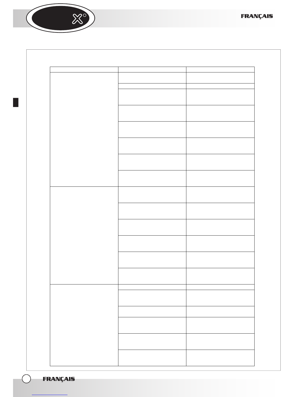
3.
LES DEGÂTS PLUS FRÉQUENTS
FRANÇAIS
FRANÇAIS
FRANÇAIS
8
DÉGÂT CAUSE SOLUTION
Hotte non pas reliée au réseau
électrique
Reliez la hotte au réseau
électrique
Hotte débranchée du four Reliez la hotte au four
Câble de liaison four hotte
interrompu ou endommagé
Il faut s’adresser à un
technicien spécialisé pour la
réparation
Moteur hotte endommagé
Il faut s’adresser à un
technicien spécialisé pour la
réparation
Condensateur de mise en
marche du moteur
endommagé
Il faut s’adresser à un
technicien spécialisé pour la
réparation
Fiche de contrôle hotte
endommagée
Il faut s’adresser à un
technicien spécialisé pour la
réparation
Fiche de contrôle four
endommagée
Il faut s’adresser à un
technicien spécialisé pour la
réparation
Quand on fait partir un cycle de
cuisson, le moteur de la hotte
ne fonctionne pas
Fiche de puissance four
endommagée
Il faut s’adresser à un
technicien spécialisé pour la
réparation
Câble de liaison four hotte
interrompu ou endommagé
Il faut s’adresser à un
technicien spécialisé pour la
réparation
Moteur hotte endommagé
Il faut s’adresser à un
technicien spécialisé pour la
réparation
Fiche de contrôle hotte
endommagée
Il faut s’adresser à un
technicien spécialisé pour la
réparation
Fiche de contrôle four
endommagée
Il faut s’adresser à un
technicien spécialisé pour la
réparation
Fiche de puissance four
endommagée
Il faut s’adresser à un
technicien spécialisé pour la
réparation
Quand on ouvre la porte, le
moteur de la hotte ne va pas à
grande vitesse
Interrupteur porte four
endommagé
Il faut s’adresser à un
technicien spécialisé pour la
réparation
Entrée d’eau fermée Ouvrez l’entrée d’eau
Collegamento alla rete idrica
eseguito in maniera non
corretta
Vérifiez la connexion au
réseau hydrique
Le Filtre d’entrée d’eau est
débouché par des impuretés Nettoyez le filtre
Electrovalve d’eau
endommagée
Il faut s’adresser à un
technicien spécialisé pour la
réparation
Sonde de température
endommagée
Il faut s’adresser à un
technicien spécialisé pour la
réparation
Le système de condensation
de l’eau ne fonctionne pas
Fiche de contrôle hotte
endommagée
Il faut s’adresser à un
technicien spécialisé pour la
réparation

UNO
R
UNO
R
FRANÇAIS
FRANÇAIS
FRANÇAIS
9
UNO
R
UNO
R
INHALTSVERZEICHNIS:
I. Anweisunge
n für den Installateur
1. Typenschild
2. CE- Prüfung
3. Anweisungen zur Installation
- 3.1 Vorbereitungen für die Installation
- 3.2 Aufstellung
- 3.3 Abziehen des Schutzfilms
4. INSTALLATION
4.1 - Elektrischer Anschluss
4.2 – Anschluss zum Ofen
4.3 - Wasseranschluss
II. ANWEISUNGEN
FÜR DEN BENUTZER
1. Anweisungen für den Benutzer
2. Gebrauchshinweise
3. Haubesbetrieb
4. Haubesreiningung
6. Abschalten im Fall von Störungen
IV. WARTUNG
1. Allgemein
2. Spezielle Wartung
3. Störungen und deren Behebung
DEUTSCH
DEUTSCH
DEUTSCH
2
page
3
pa
ge 3
page 3
page 3
page 4
page 6
page 6
page 6
page 6
page 6
page 6
page 7
page 7
page 7
page 8

UNO
R
UNO
R
I.
ANWEISUNGEN FÜR
DEN INSTALLEUR
Sehr geehrter Kunde, wir danken und
gratulieren Ihnen zum Kauf dieses UNOX
Produktes. Bitte befolgen Sie die Anweisungen
und Regeln zu den einzelnen Schritten der
Installation, Benutzung und Wartung im
Sinne Ihrer persönlichen Sicherheit und
der fachgemäßen Nutzung des gekauften
Produktes.
Bitte lesen Sie diese Betriebsanleitung vor
Benutzung und Installation genau durch!
1.
TYPENSCHILD
2.
GERÄTE PRÜFUNG
Das CE-Kennzeichnen an den Geräten und in
dieserBetriebsanleitung unterliegen den folgenden
EG –Richtlinien:
ABZUGSHAUBE - mod. XC535 XC595 :
- Niederspannungsrichtlinie
DBT 73/23/EEC und 93/68/EEC,
nach EN-Norm EN60335-2-42+A1
- Richtlinie für Elektromagnetische Verträglichkeit,
nach EN-Norm EN60555-3 und EN55014.
3.
INSTALLATION
- VORINSTALLATION
Alle elektrischen Anschlüsse und
Wasserinstallationen müssen von Fachpersonal
nach den gültigen deutschen Normen, Regeln
und Sicherheitsrichtlinien ausgeführt werden.
3.1
Prüfen des Platzes zur Aufstellung des Gerätes
Vor dem Aufstellen des Gerätes, prüfen
Sie bitte alle Maße, elektrische Anschlüsse,
Wasseranschlüsse, entsprechend des Beiblattes
„Technische Daten“
3.2
AUFSTELLUNG
Die Abzugshaube muss auf dem Ofen gelegt
werden und am Ofen durch die
eigens dazu
bestimmten Schrauben befestigt werden
In der Ruckseite müssen Sie Stellschraube des
Ofensrücken benutzen.
In der Vorderseite müssen Sie die eigens
dazu bestimmten Bohrschrauben (die mit der
Abzugshaube ausgerüstet werden)
DEUTSCH
DEUTSCH
DEUTSCH
3
UNOX S.p.A.
FYQTU\\1bdYWYQ^Qd_"(#
#% ! FYW_TQbjUbU@49D
1<I
MOD
.: XL195
DATE
TYPE: kW: POWER: FREQUENCY:
MOD: S/N
GERÄTESERIE
BETRIEBSPANNUNG
MODELLBEZEICHNUNG
KENNZEICHEN
LEISTUNG
FYQTU\\1bdYWYQ^Qd_"(#
#% ! FYW_TQbjUbU@49D
.: XL195

UNO
R
UNO
R
Das Gerät muß entsprechend den
Sicherheitsvorschriften und Normen wie
nachfolgend beschrieben aufgestellt werden.
Die Seiten und Oberflächen des Gerätes müssen so
aufgestellt
werden, so daß ein einfacher Elektrischer Anschluß
und die normale Wartung und Reparaturen
möglich sind.
Das Gerät ist nicht einbaufähig, und nicht für
Reihenaufstellung geeignet.
Falls das Gerät in der Nähe von Mauern, Wänden,
Küchenschränken, Deko-Materialien aufgestellt
werden muß, ist es wichtig das diese Teile aus
einem nicht brennbaren Material bestehen.
Bitte prüfen Sie dies genau, falls die Teile aus
brennbarem Material bestehen, verkleiden Sie
dies mit nicht brennbarer Isolierung oder entfernen
Sie diese Teile das dem Umfeld des Gerätes. Bitte
prüfen Sie hier den Schutzvorschriften vor Feuer und
Rauch genau.
3.3
ABZIEHEN DES SCHUTZFILMS
Ziehen Sie unbedingt den weißen Schutzfilm von
den Außen und Innenseiten des Gerätes ab, Dies
ist wichtig um ein verbrennen des Schutzfilms
während des Betriebes zu verhindern! Falls ein
Rückstand verbleibt, entfernen Sie den Rückstand
mit einem Lösungsmittel. Alle Installations- und
Wartungsarbeiten dürfen nur von geschulten
Fachpersonal durch-geführt werden.
4.
INSTALLATION
4.1
ELEKTRISCHER ANSCHLUSS
a-
Die Installation zum Stromversorgungsnetz muß
nachden Vorschriften des Netzbetreibers vor Ort
entsprechen.
Vor dem Anschluß stellen Sie bitte sicher dass:
-
Die Voltzahl und die Stromfrequenz des
Stromnetzes mit den Angaben auf dem
Typenschild des Gerätes übereinstimmen.
-
Die Steckdose die Sicherheitserdung hat. Sie
soll die Last des Geräts, die auf dem Schild
Technischen Daten gezeigt werden, tragen.
-
Die Steckdose passend zum Steckdose des
Geräts (Schuko 16 A) wird.
keine Verlängerungstücke und Vielfachsteckdosen
benutzen
Plazieren Sie den Stecker zwischen dem Gerät und
dem Stromversorgungs-netz nach der Installation,
die Kontakte dürfen nur ein Minimum Öffnungs-
Abstand von 3 mm von der Zuleitung (z.B.: ein
magnetthermischer Trennschalter).
Wenn das Gerät arbeitet darf die Spannung nicht
mehr als ± 10 % von der normalen Spannung
abweichen.
Die Verbindung zum Stromnetz wird durch
einen 16A Schukostecker hergestellt
Die Temperatur jeder Punkte des Speisekabel soll
die Umgebungstemperatur von nicht mehr als 50
°C Übersteigen.
Das Gerät muss mit einem allpoligen
Netztrennschalter (Magnet- Thermoschalter)
mit einer Kontaktöffnung von mindestens 3mm
vom Netz getrennt
werden, welcher zudem leicht zugänglich ist.
-Wenn das Gerät arbeitet, darf die
Versorgungsteilspannung nicht mehr als ± 10%
vom Wert der Nennspannung abweichen,
Die Aquipotential Ausgleichsleitung muß einen
Querschnitt von 10 mm
2
haben.
4.2
ABZUGSHAUBE ANSCHLUSS AM
OFEN
ELEKTRISCHER ANSCHLUSS
Zum Anschluss der Abzugshabe am
Ofen verfahren Sie wie folgt:
1-
Entfernen Sie die Rückwand des
Ofens;
2-
Verbinden Sie das Steuerkabel der
Abzugshaube mit den dafür vorgesehenen
Anschlüssen auf der Relaisplatine (siehe
Bild);
DEUTSCH
DEUTSCH
DEUTSCH
4
This manual suits for next models
1
Table of contents
Languages:
Other Unox Ventilation Hood manuals


Popular Ventilation Hood manuals by other brands

Novy
Novy Mood 7550 Operating and installation instructions

Imperial
Imperial 42NV-WH Installation instructions & warranty information

IKTCH
IKTCH IKB01 Series Installation guide & user manual

JUNO
JUNO JDK5575E Instruction booklet

Electrolux
Electrolux DCE3960HM installation manual

Wolf
Wolf CTWH30 Specifications


