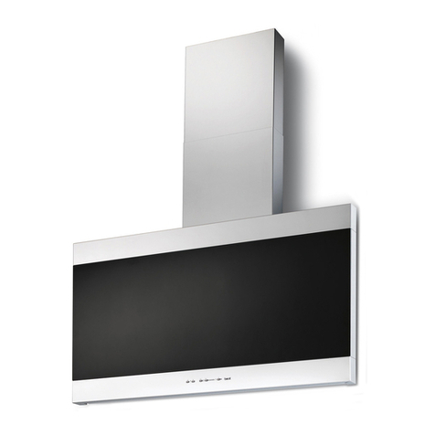
Best IS23 User manual

- 1 -
BESTBYBROANP.O.Box140Hartford,WI53027
ENGLISH......................................2
FRANÇAIS..................................12
ESPAÑOL...................................24
Model IS23

- 2 -
READ AND SAVE THESE INSTRUCTIONS
WARNING
SUITABLEFORUSEIN HOUSEHOLDCOOKINGAREA.
TO REDUCE THE RISK OF FIRE, ELECTRICAL SHOCK, OR INJURY TO PERSONS,
OBSERVETHE FOLLOWING:
1. Use this unit only in the manner intended by the manufacturer. If you have questions,
contactthemanufacturer atthe addressortelephone numberlistedinthewarranty.
2. Before servicing or cleaning unit, switch power off at service panel and lock service
paneltoprevent powerfrombeing switchedon accidentally.Whenthe servicediscon-
nectingmeanscannotbelocked, securelyfasten aprominentwarningdevice,such as
atag,to theservicepanel.
3. Installation work and electrical wiring must be done by a qualified person(s) in accor-
dancewithall applicablecodesand standards,including fire-ratedconstructioncodes
andstandards.
4. Sufficientairisneededforpropercombustionandexhaustingofgasesthroughtheflue
(chimney)offuelburningequipmenttoprevent backdrafting.Follow theheating equip-
mentmanufacturer’sguidelines and safetystandardssuch as thosepublishedby the
National Fire Protection Association (NFPA), and theAmerican Society for Heating,
RefrigerationandAirConditioningEngineers(ASHRAE),andthelocal codeauthorities.
5. When cutting or drilling into wall or ceiling, do not damage electrical wiring and other
hiddenutilities.
6. Ductedfansmust always bevented to theoutdoors.
7. Donotuse thisunitwith anysolid-statespeed controldevice.
8. To reduce the risk of fire, use only steel ductwork.
9. Thisunitmust begrounded.
TOREDUCETHE RISKOFARANGETOPGREASEFIRE:
A. Never leave surface units unattended at high settings. Boilovers cause smoking and greasy
spillovers that may ignite. Heat oils slowly on low or medium settings.
B. Always turn hood ON when cooking at high heat or when cooking flaming foods.
C. Clean ventilating fans frequently. Grease should not be allowed to accumulate on fan or
filter.
D. Use proper pan size. Always use cookware appropriate for the size of the surface element.
WARNING
TO REDUCETHE RISK OF INJURYTO PERSONS IN THE EVENTOF ARANGE TOP
GREASEFIRE, OBSERVETHEFOLLOWING:*
1. SMOTHERFLAMESwithaclose-fittinglid,cookiesheet,ormetaltray,thenturnoffthe
burner. BECAREFULTOPREVENTBURNS. Iftheflamesdonot gooutimmediately,
EVACUATEANDCALLTHEFIREDEPARTMENT.
2. NEVERPICKUPAFLAMINGPAN-Youmaybeburned.
3. DONOTUSEWATER,including wetdishclothsortowels- violentsteam explosionwill
result.
4. Useanextinguisher ONLYif:
A. Youknow youhaveaClassABCextinguisher andyoualreadyknowhowtooperate
it.
B. The fireis smallandcontained inthearea whereitstarted.
C. The firedepartment isbeing called.
D. Youcanfight the firewithyour back toanexit.
*Basedon “KitchenFireSafetyTips” publishedbyNFPA.
!
INTENDED FOR DOMESTIC COOKING ONLY
!

- 3 -
!
CAUTION
1. Toreduceriskoffire andto properlyexhaust air,be sureto ductairoutside.Donotvent
exhaustairinto spaceswithinwalls orceilingsor into attics,crawl spaces, orgarages.
2. Takecarewhen usingcleaningagents ordetergents.
3. Avoidusingfood productsthatproduceflamesunder theRange Hood.
4. Forgeneralventilatinguseonly. Donotusetoexhausthazardousorexplosivematerials
andvapors.
5. Toavoidmotor bearingdamageand noisy and/orunbalancedimpellers, keep drywall
spray, construction dust,etc.offpower unit.
6. Yourhoodmotor has athermaloverload whichwillautomatically shutoff themotorif it
becomesoverheated.Themotorwill restartwhenitcoolsdown. Ifthe motorcontinues
toshutoff and restart,havethe hood serviced.
7. Forbestcapture ofcookingimpurities, thebottomof thehood shouldbea minimumof
24" and a maximum of 30" above the cooking surface. See “Adjust Support Frame”
sectionformountingrestrictions.
8. Two installersare recommendedbecauseof thelargesizeandweight ofthishood.
9. This product is equipped with a thermostat which may start blower automatically. To
reduce the risk of injury and to prevent power from being switched on accidentally,
switchpoweroff at servicepaneland lock ortagservice panel.
10.Usewith approvedcord-connectionkit only.
11.Please readspecification labelonproductforfurtherinformationand requirements.

- 4 -
OPERATION
Controls
The hood is operated using the (4) push-
buttonslocatedateye-level,onthefront edge
of the hood.
The light switch turns the lights on and off.
The blower on-low / off switch turns the
blower on to its lowest running speed. The
blower must be turned on using this switch.
Turn the blower off by pressing this switch a
second time.
The blower medium speed switch changes the blower speed to medium. This
switch works only if the blower is already running at low or high speed.
The blower high speed switch changes the blower speed to high. This switch
works only if the blower is already running at low or medium speed.
The pilot lamp lights up whenever the blower is on.
LIGHT
SWITCH
BLOWER
ON-LOW /
OFF
SWITCH PILOT
LAMP
BLOWER
MEDIUM
SPEED
BLOWER
HIGH
SPEED
LIGHT BULBS
Thishoodrequirestwo9-Wattfluorescentlight
bulbs.
ALWAYS SWITCH OFF THE ELECTRICITY
SUPPLY BEFORE CARRYING OUT ANY
OPERATIONS ON THE APPLIANCE.
To change bulbs:
1. Remove the light lens cover.
2. Remove the bulb by pulling sideward (Do not rotate). CAUTION: BULB MAY
BEHOT!
3. Replace with a bulb of the same type.
REMOVE LIGHT LENS COVER

- 5 -
GREASEFILTERS
MAINTENANCE
Grease Filters
The grease filters should be cleaned fre-
quently. Use a warm detergent solution.
Grease filters are dishwasher safe.
See “Install Filter” section for installation and
removal instructions.
Ductfree Filters
The ductfree filters should be changed every 6 months. See “Install Filter” section
for installation and removal instructions.
Hood Cleaning
Stainless steel is one of the easiest materials to keep clean. Occasional care will
help preserve its fine appearance.
Cleaning tips:
•Hot water with soap or detergent is all that is usually needed.
•Follow all cleaning by rinsing with clear water. Wipe dry with a clean, soft cloth
to avoid water marks.
•For discolorations or deposits that persist, use a non-scratching household
cleanser or stainless steel polishing powder with a little water and a soft cloth.
•For stubborn cases, use a plastic scouring pad or soft bristle brush together
with cleanser and water. Rub lightly in direction of polishing lines or "grain" of
the stainless finish. Avoid using too much pressure which may mar the surface.
•DO NOT allow deposits to remain for long periods of time.
•DO NOT use ordinary steel wool or steel brushes. Small bits of steel may
adhere to the surface causing rust.
•DO NOT allow salt solutions, disinfectants, bleaches, or cleaning compounds
to remain in contact with stainless steel for extended periods. Many of these
compounds contain chemicals which may be harmful. Rinse with water after
exposure and wipe dry with a clean cloth.
Painted surfaces should be cleaned with warm water and mild detergent only.

- 6 -
PREPARE THE HOOD
Unpack hood and check contents.
You should receive:
1 - Hood
1 - Decorative Flue Assembly
1 - Support Frame
1 - Parts Bag (B080810532) containing:
4 - Mounting Screws (6 x 70mm)
8 - Washers 6.4mm
4 - Mounting Screws (3.9 x 9.5mm Pan Head)
4 - Nuts
1 - Duct Collar
1 - Ductfree Plenum
1 - Electrical Box Assembly
1 - Installation Instructions
1 - Warranty Card
SUPPORT FRAME
DECORATIVE
FLUE
8 MOUNTING
SCREWS
(3.9x9.5mm
Pan Head)
8 WASHERS
6.4mm
4NUTS
4MOUNTINGSCREWS
(6x70mm)
DUCTCOLLAR
DUCTFREE PLENUM
ELECTRICAL BOX
ASSEMBLY

- 7 -
INSTALL THE DUCTWORK
Ductedconfigurationonly.
NOTE: To reduce the risk of fire, use only
metal ductwork.
1. Decide where the ductwork will run between
the hood and the outside.
2. A straight, short duct run will allow the hood
to perform most efficiently.
3. Long duct runs, elbows, and transitions will
reduce the performance of the hood. Use
as few of them as possible.
4. Install a roof or wall cap. Connect 6" round
metal ductwork to cap and work back to-
wards hood location. Use duct tape to seal
the joints between ductwork sections.
INSTALL SUPPORT SYSTEM
1. At hood location, install 2 X 4 cross fram-
ingbetweenceilingjoistsusingdimensions
shown.
2. Finish the ceiling surface. Be sure to mark
the location of the ceiling joists and cross
framing.
ROOF CAP
6” ROUND
DUCT
EAVE
VENT
HOOD
24” TO 30” ABOVE
COOKING SURFACE
(See “Adjust Support
Frame” section for
mounting restrictions.)
6” ROUND
ELBOW
DECORATIVE
FLUE
TOP VIEW OF
SUPPORT FRAME
7”
7”
CEILING
JOISTS
CROSS FRAMING
SUPPORT
FRAME
7”
DRYWALL

- 8 -
ADUCTFREE
PLENUM
6” ROUND
METAL
DUCT
DUCTFREE CONFIGURATION
DUCT
CONNECTOR
OF THE
DUCTFREE
PLENUM
INSTALL DUCTFREE PLENUM
Ductedconfigurationonly.
1. Remove (4) screws and washers from the
support frame assembly and separate both
halves.
2. Snap the 6" plastic duct connector into the
opening of the metal plenum.
3. Attach a piece of 6" metal duct to the con-
nector of the plenum. Use aluminum duct
tape to seal joints and make air tight.
4. Insert the ductfree plenum up into the upper
support frame. Air outlets “A” of the plenum
must be aligned with openings in the upper
support frame.
5. Securetheplenumtotheuppersupportframe
with (4) 3.9 x 9.5 mm screws.
ADJUST SUPPORT FRAME
HEIGHT
Ducted and Ductfree configurations.
NOTE:FORINSTALLATION INROOMS HAV-
ING 10-FOOT CEILINGS, PURCHASE FLUE
EXTENSION MODEL FEXTIS23. DISCARD
THE SUPPORT FRAME PROVIDED WITH
THEHOOD.USETHELONGERFRAMESUP-
PLIEDWITHTHE FLUEEXTENSION.
1. Remove (4) screws and washers from the
support frame assembly and separate both
halves.
2. Determine the distance between the range
hood and the cooktop. See chart below for
mounting height restrictions. Hood must be
mounted a minimum of 24” above the
cooktop.Amaximumof30”isrecommended
for best capture of cooking impurities. Dis-
tances over 30” are at the user’s discretion.
3. Adjusttheoverallheightofthesupportframe.
Refertothechartto adjustthesupportframe
to the proper length.
LOWER
SUPPORT
FRAME
SUPPORT
FRAME
LENGTH
CEILING
HEIGHT
8 FEET
9 FEET
HOOD DISTANCE ABOVE 36” HIGH COOK TOP
24” 25” 26” 27” 28” 29” 30”
SUPPORT FRAME LENGTH
25-3/8” 24-3/8” 23-3/8” 22-3/8”
10 FEET WITH
FEXTIS23
33-3/8” 32-3/8” 31-3/8”
47-3/8” 46-3/8” 45-3/8” 44-3/8” 43-3/8”
4. Reassemble the upper and lower support frame with (4) sheet metal screws and
washers.

- 9 -
INSERT SUPPORT FRAME
1. Attach the support frame assembly to the
ceiling with (4) washers and (4) 6 x 70mm
mounting screws. Make sure the “UP” ar-
row is pointed towards the ceiling. The side
marked “FRONT” must align with the range
hood’s control panel.
UPPER SUPPORT FRAME
WASHERS
6 X 70mm
MOUNTING SCREWS
INSTALL DECORATIVE FLUES
NOTE:FORINSTALLATION INROOMSHAV-
ING 10-FOOT CEILINGS, PURCHASE FLUE
EXTENSION MODEL FEXTIS23. DISCARD
THEUPPER DECORATIVEFLUEPROVIDED
WITH THE HOOD. REPLACE WITH THE
LONGERUPPERFLUESUPPLIEDWITHTHE
FLUEEXTENSION.
1. Raise the upper decorative flue into posi-
tion on the support frame. Secure the upper
flue to the support frame with (2) 3.9 x 9.5
mm screws.
2. Slidethelowerflueovertheupperflue.Tem-
porarily hold the flue up until the hood is
installed and electrical connection are
made.
UPPER
DECORATIVE
FLUE
LOWER
DECORATIVE
FLUE
INSTALL DUCT CONNECTOR
Ductfree configurations only.
1. Remove and discard the backdraft damper
flaps from the duct connector.
2. Trim off excess duct to within 2-1/2” of the
bottom of the support frame.
Ducted and Ductfree configurations.
3. Install the duct connector in the round open-
ing on top of the range hood. Push down
until it snaps into place and is securely en-
gaged.
Ducted configurations only.
4. Attach 6” round metal duct to the duct con-
nector.Useducttapetosealjointsandmake
air tight.
DUCT
CONNECTOR
3.9 X 9.5 mm
SCREWS

- 10 -
INSTALL RANGE HOOD
1. Raise the hood up into position under the
range hood. control switches must be lo-
cated on the support frame side marked
“FRONT”.
2. Attach the hood using (4) washers and (4)
hex nuts.
INSTALL ELECTRICAL WIRING
NOTE:ELECTRICAL WIRING MUST BE DONE
BYAQUALIFIEDPERSON(S)INACCORDANCE
WITH ALL APPLICABLE CODES AND STAN-
DARDS,INCLUDINGFIRE-RATEDCONSTRUC-
TION CODESAND STANDARDS. THIS RANGE
HOOD MUST BE PROPERLY GROUNDED.
TURN OFF POWER AT SERVICE ENTRANCE
BEFORE WIRING THIS HOOD.
1. Remove screws and cover from the electri-
cal wiring box.
2. Remove a knockout from the bottom of the
wiring box and one from the side.
3. Install the plastic bushing into the bottom
hole. Route the black, white, and green
ground wires from the hood into the wiring
box.
4. Secure the wiring box to the hood with (2)
3.9 x 9.5 mm screws.
5. Feed 6” of power cable into the wiring box.
Secure cable to the wiring box using an
appropriate connector.
6. Make electrical connections. Wire black to
black, white to white, and green to ground.
7. Push all wiring inside the wiring box. Make
sure wires are not pinched. Reinstall cover
and secure with (2) 3.9 x 9.5 mm screws.
8. Move the lower flue down into position on
the hood. Secure with (2) 3.9 x 13 mm
screws.
WIRING BOX
COVER
BOLT
NUT
WIRING WIRING
BOX
BUSHING

- 11 -
DUCTFREE FILTER
INSTALLATION
Ductfreeconfigurationonly.
1. Purchase a ductfree filter kit (Model “Round
Filter”) from your dealer.
2. Position thefiltersoverthefiltersupportson
the blower.
3. Toinstall:Rotatefilterstolockfiltersinplace.
4. To remove: Reverse rotation and pull the
filteroff.
Ducted and Ductfree configurations.
1. To remove grease filters: Grip the latch tab
and pull it down. This will disengage the
filter from the hood. Tilt the filter downward
to remove.
2. To install the grease filters: Align rear filter
tabs with slots in the hood. Pull latch tab
down, push filter into place, and release.
Make sure the filters are securely engaged
after assembly.
DUCTFREE
FILTERS
GREASEFILTERS

- 12 -
WARRANTY
BROAN ONE YEAR LIMITED WARRANTY
Broan warrants to the original consumer purchaser of its products that such products will
be free from defects in materials or workmanship for a period of one year from the date
of original purchase. THERE ARE NO OTHER WARRANTIES, EXPRESS OR IMPLIED,
INCLUDING, BUT NOT LIMITED TO, IMPLIED WARRANTIES OR MERCHANT ABIL-
ITY OR FITNESS FOR A PARTICULAR PURPOSE.
During this one-year period, Broan will, at its option, repair or replace, without charge, any
product or part which is found to be defective under normal use and service.
THIS WARRANTY DOES NOT EXTEND TO FLUORESCENT LAMP STARTERS,
TUBES, HALOGEN AND INCANDESCENDT BULBS. This warranty does not cover (a)
normal maintenance and service or (b) any products or parts which have been subject
to misuse, negligence, accident, improper maintenance or repair (other than by Broan),
faulty installation or installation contrary to recommended installation instructions.
The duration of any implied warranty is limited to the one-year period as specified for the
express warranty. Some states do not allow limitation on how long an implied warranty
lasts, so the above limitation may not apply to you.
BROAN’S OBLIGATION TO REPAIR OR REPLACE, AT BROAN’S OPTION, SHALL BE
THE PURCHASER’S SOLE AND EXCLUSIVE REMEDY UNDER THIS WARRANTY.
BROAN SHALL NOT BE LIABLE FOR INCIDENTAL, CONSEQUENTIAL OR SPECIAL
DAMAGES ARISING OUT OF OR IN CONNECTION WITH PRODUCT USE OR PER-
FORMANCE. Some states do not allow the exclusion or limitation of incidental or conse-
quential damages, so the above limitation or exclusion may not apply to you.
This warranty gives you specific legal rights, and you may also have other rights, which
vary from state to state. This warranty supersedes all prior warranties.
To qualify for warranty service, you must (a) notify Broan at the address stated below or
telephone: 1-800-637-1453, (b) give the model number and part identification and (c)
describe the nature of any defect in the product or part. At the time of requesting warranty
service, you must present evidence of the original purchase date.
BEST BY BROAN, P.O. Box 140 Hartford, Wisconsin 53027

- 13 -
VEUILLEZ LIRE CES DIRECTIVES ET LES CONSERVER
AVERTISSEMENT
CONVIENTÀLAPIÈCEDECUISINED’UNEHABITATION.
OBSERVEZLESDIRECTIVESCI-DESSOUSDE MANIÈREÀRÉDUIRELESRISQUES
D'INCENDIE, DE CHOC ÉLECTRIQUE OU DE BLESSURES CORPORELLES :
1. N'utilisez cet appareil que de la manière prévue par le fabricant. Si vous avez des
questions, communiquez avec le fabricant à l'adresse ou au numéro de téléphone
indiquésdans lagarantie.
2. Avantdeprocéderàlaréparationouàl'entretiendel'appareil,coupezl'alimentationdu
panneaud'entréed'électricitéetverrouillezl'interrupteurprincipalafind'empêcherquele
courantnesoit accidentellementrétabli.S'il estimpossiblede verrouiller l'interrupteur
principal,fixezsolidementunmessaged'avertissement,parexempleuneétiquette,au
panneaud'entrée d'électricité.
3. Laposedel'appareil etlestravauxd'électricitédoiventêtreeffectuéspardespersonnes
qualifiéesconformémentà laréglementationen vigueur,notammentles normesdela
constructionayanttrait àlaprotection contreles incendies.
4. Pouréviterlesrefoulements,l'apportd'airdoitêtresuffisantpourbrûlerlesgazproduits
par les appareils à combustion et les évacuer dans le conduit de fumée (cheminée).
Respectezlesdirectivesdufabricantdel'appareildechauffageetlesnormesdesécurité,
notammentcellespubliéesparlaNationalFireProtectionAssociation(NFPA),l’American
SocietyforHeating,RefrigerationandAirConditioningEngineers(ASHRAE)etlescodes
desautoritéslocales.
5. Veillezànepasendommagerlecâblageélectriqueoud'autreséquipementsnonapparents
lorsdela découpeoudu perçagedu muroudu plafond.
6. Lesventilateurscanalisés doiventtoujoursêtreventilésà l'airlibre.
7. N'utilisez pas de commande de régime à semi-conducteurs conjointement avec cet
appareil.
8. Pourréduireles risquesd'incendie, utilisezseulement desconduitsenacier.
9. Cetappareildoit êtremisà laterre.
POURRÉDUIRELES RISQUESD'INCENDIECAUSÉS PAR DELAGRAISSE SURLE
PLAN DE CUISSON :
A. Nelaissezjamaislesélémentsdesurfaceallumésàhautetempérature.Lesdébordementspeuvent
causerdelafuméeetoccasionnerdesécoulementsdegraisseinflammables.L'huiledoitêtrechauffée
graduellementàbasseouàmoyennetempérature.
B. Mettez toujoursla hotteEN FONCTION(ON) lorsde lacuisson àhaute températureou lorsde la
cuissond'alimentsàflamber.
C. Nettoyezsouventlahotte.Nelaissezpaslagraisses'accumulersurleventilateuroulefiltre.
D. Utilisezdescasserolesdedimensionappropriée.Utiliseztoujoursunebatteriedecuisineadaptéeàla
dimensiondesélémentsdesurface.
!
POUR USAGE DOMESTIQUE SEULEMENT
!

- 14 -
!
ATTENTION
1. Pourréduireles risqued'incendie etévacuerl'aircorrectement,assurez-vous qu'ilest
canaliséàl'extérieur.Nepasévacuerl'airdansdesespacesenfermés pardesmursou
unplafondoudansun grenier, unvidesanitaireouun garage.
2. Faitesattentionlorsque vousutilisezdesagentsnettoyants oudes détergents.
3. Évitezd'utiliserdes produitsalimentaires pouvantproduire desflammes sousla hotte.
4. Cet appareil ne doit servir qu'à la ventilation générale. Il ne doit pas être utilisé pour
éliminerdesmatières oudesvapeurs dangereusesou explosives.
5. Pouréviterd'endommager lesroulements demoteur, dedéséquilibrerlespalesoude
lesrendre bruyantes,débarrassez l'appareildelapoussièredeplâtre,deconstruction,
etc.
6. Lemoteurde lahotte estmuni d'undispositif deprotection desurchargeélectriquequi
coupeautomatiquementlemoteurencasdesurchauffe.Ilse remetenmarchelorsqu'il
arefroidi.Faitesréparerlahottesi lemoteur continueà fonctionnerparintermittence.
7. Pour mieux capter les vapeurs de cuisson, le bas de la hotte doit être au minimum à
61 cm (24 po) et au maximum à 76 cm (30 po) de la surface de cuisson. Pour les
restrictions s’appliquant au montage, voir la section « Réglage de la hauteur du châssis
de suspension ».
8. Ilestrecommandéquelesinstallateurssoientdeux,compte tenudelatailleetdupoids
decettehotte.
9. Ceproduitestdotéd'unthermostatquipeutfairedémarrerautomatiquementleventilateur.
Pourréduirelesrisquesdeblessures,coupez l'alimentationélectrique surle panneau
d'électricité et verrouillez-le ou accrochez-y une étiquette de manière à éviter que le
courantnesoitrétablipar accident.
10. Àutiliseruniquementavecl'ensemblede connexionapprouvé.
11. Veuillezlirel'étiquettedespécificationsduproduitpourobtenirplusderenseignements,
notammentsurles normes.
AVERTISSEMENT
OBSERVEZ LES CONSIGNES SUIVANTES DE MANIÈRE À RÉDUIRE LES
RISQUES DE BLESSURES CORPORELLES EN CAS D'INCENDIE CAUSÉ PAR DE
LA GRAISSE SUR LE PLAN DE CUISSON :*
1. ÉTOUFFEZLESFLAMMESàl'aided'uncouvercleétanche,d'unetôleàbiscuitsoud'un
plateau en métal puis éteignez le brûleur. FAITES ATTENTION DE NE PAS VOUS
BRÛLER.Si lesflammes nes'éteignent pasimmédiatement, QUITTEZLESLIEUXET
APPELEZLESERVICEDESINCENDIES.
2. NESOULEVEZJAMAISUNECASSEROLEENFLAMMES-vouspourriezvousbrûler.
3. N'UTILISEZPASD'EAU,ni deserviettes oude lingesmouillés -une violenteexplosion
devapeurpourrait survenir.
4. Utilisez un extincteur SEULEMENT si :
A. Vous savez qu'il est de classe ABC et vous connaissez déjà son mode de
fonctionnement.
B. L'incendie n'estpas trèsimportantet nesepropage pas.
C. Vous avezdéjàtéléphonéauservice desincendies.
D. Vouspouvezcombattre l'incendieenfaisantdosà unesortie.
* Conseils tirés de la publication de la NFPA« Kitchen Fire Safety Tips ».

- 15 -
UTILISATION
Commandes
La hotte fonctionne à l'aide de quatre (4)
boutons-poussoirssituésàhauteurdesyeux,
sur la face avant.
L'interrupteur d'éclairage allume et éteint
les lumières.
L'interrupteur de ventilateur régime lent
marche/arrêt fait démarrer le ventilateur à
son régime le plus lent. Le ventilateur doit
êtremisenmarche àl'aidedecetinterrupteur.
Pour arrêter le ventilateur, il suffit d'appuyer
une deuxième fois sur l'interrupteur.
L'interrupteur de ventilateur régime moyen place le ventilateur en vitesse
moyenne. Cet interrupteur ne fonctionne que si le ventilateur est déjà en marche
en régime lent ou élevé.
L'interrupteur de ventilateur régime élevé place le ventilateur en haute vitesse.
Cet interrupteur ne fonctionne que si le ventilateur est déjà en marche en régime
lent ou moyen.
Le témoin lumineux s'allume dès que le ventilateur est en marche.
INTERRUPTEUR
D'ÉCLAIRAGE
VENTILATEUR
RÉGIME LENT
MARCHE/ARRÊT TÉMOIN
LUMINEUX
VENTILATEUR
RÉGIME MOYEN
VENTILATEUR
RÉGIME ÉLEVÉ
AMPOULES
Cette hotte requiert deux ampoules fluores-
centes de 9 watts.
COUPEZ TOUJOURS L’ALIMENTATION
ÉLECTRIQUEAVANT D’EFFECTUERTOUTE
OPÉRATION SUR CET APPAREIL.
Pour remplacer les ampoules :
1. Retirez la lentille d'éclairage.
2. Retirez l'ampoule en la tirant sur le côté (et non en la tournant). ATTENTION :
L'AMPOULE PEUT ÊTRE BRÛLANTE !
3. Remplacez-la par une ampoule du même type.
RETIREZLALENTILLE D'ÉCLAIRAGE

- 16 -
FILTRESÀGRAISSE
ENTRETIEN
Filtres à graisse
Les filtres à graisse doivent être nettoyés
fréquemment. Utilisez une solution tiède de
détergent. Ces filtres peuvent aller au lave-
vaisselle.
Voir la section « Installation des filtres » pour
les instructions concernant leur pose et leur
démontage.
Filtres non canalisés
Les filtres non canalisés doit être remplacés tous les 6 mois. Voir la section
« Installation des filtres » pour les instructions concernant leur pose et leur
démontage.
Nettoyage de la hotte
L'acier inoxydable est l'un des matériaux les plus faciles à nettoyer. Quelques
soins contribueront à préserver sa belle apparence.
Conseils de nettoyage :
•Il suffit habituellement d'utiliser de l'eau chaude savonneuse ou additionnée
de détergent.
•Après le nettoyage, rincez toujours à l'eau claire. Essuyez la surface avec un
chiffon propre et doux pour éviter les stries.
•Pour les ternissures ou les dépôts tenaces, utilisez un nettoyant domestique
non-abrasif ou une poudre à polir l'acier inoxydable avec un peu d'eau et un
chiffon doux.
•Pour la saleté rebelle, utilisez un tampon à récurer en plastique ou une brosse
à poils doux avec un nettoyant et de l'eau. Frottez doucement dans le sens des
lignes de polissage ou du « grain » de l'acier. Évitez de trop appuyer au risque
de gâcher la surface.
•NE LAISSEZ PAS les dépôts s'accumuler trop longtemps.
•N'UTILISEZ PAS une laine d'acier ordinaire ou une brosse d'acier. De petites
particules d'acier risqueraient d'adhérer à la surface et de la faire rouiller.
•NE LAISSEZ PAS une solution saline, un désinfectant, de l'eau de javel ou tout
autre produit détachant rester longtemps en contact avec l'acier inoxydable.
Bon nombre de ces nettoyants contiennent des produits pouvant en altérer la
surface. Après l'utilisation du nettoyant, rincez la surface à l'eau et essuyez-la
avec un chiffon propre.
Nettoyez les surfaces peintes uniquement à l'eau tiède avec un détergent doux.

- 17 -
PRÉPARATION DE LA HOTTE
Déballez la hotte et vérifiez le contenu de la boîte.
Celle-ci doit contenir les éléments suivants :
1 - Hotte
1 - Conduit décoratif de cheminée
1 - Châssis de suspension
1 - Sac de plastique (B080810532) contenant :
4 - Vis de montage (6 x 70 mm)
8 - Rondelles de 6,4 mm
4 - Vis de montage (3,9 x 9,5 mm - à tête
cylindrique)
4 - Écrous
1 - Raccord de conduit
1 - Dérivation non canalisée
1 - Boîtier de connexion électrique
1 - Directives d'installation
1 - Carte de garantie
CHÂSSIS DE
SUSPENSION
CONDUIT DÉCORATIF
DE CHEMINÉE
8 VIS DE MONTAGE
(3,9 x 9,5 mm - à
tête cylindrique)
8 RONDELLES
DE 6,4 MM
4 ÉCROUS
4 VIS DE MONTAGE
(6 x 70 MM)
RACCORD DE
CONDUIT
DÉRIVATION NON
CANALISÉE
BOÎTIER DE CONNEXION
ÉLECTRIQUE

- 18 -
POSE DU CONDUIT
Installation avec conduit seulement.
REMARQUE : Pour réduire les risques
d'incendie, utilisez seulement des conduits
en métal.
1. Planifiez la pose du conduit en déterminant
son tracé entre la hotte et l'extérieur de la
maison.
2. Untracédroitetcourtpermetàlahotted'être
plus efficace.
3. Des conduits longs, des coudes et des tran-
sitions réduisent son efficacité. N'en utilisez
que le moins possible.
4. Installez le chapeau mural ou de toit.
Connectez un conduit rond en métal de
15,2 cm (6 po) au chapeau en progressant
verslahotte.Scellezlesjointsavecduruban
à conduit à chaque section.
INSTALLATION DU SYSTÈME
DE SUSPENSION
1. À l’emplacement choisi pour la hotte,
installez des entretoises de 2 X 4 entre les
solives du plafond selon les dimensions
illustrées.
2. Finissez la surface du plafond. Marquez la
position des solives et des entretoises.
CHAPEAU DE TOIT
CONDUIT ROND
DE 15,2 CM (6 PO)
ÉVENT
D’AVANT-
TOIT
HOTTE
61 À 76 CM (24 À 30 PO)
AU-DESSUS DE LA
SURFACE DE CUISSON
(Pour les restrictions
s’appliquant au montage,
voir la section « Réglage de
la hauteur du châssis de
suspension ».)
COUDE ROND
DE 15,2 CM
(6 PO)
CONDUIT
DÉCORATIF
DE
CHEMINÉE
17,8 CM
(7 PO)
VUE DE DESSUS DU
CHÂSSIS DE SUSPENSION
17,8 CM
(7 PO)
17,8 CM
(7 PO)
SOLIVES
ENTRETOISE
CHÂSSIS DE
SUSPENSION
CLOISON SÈCHE

- 19 -
ADÉRIVATION
NON
CANALISÉE
CONDUIT
MÉTALLIQUE
ROND DE
15,2 CM
(6 PO)
INSTALLATION SANS CONDUIT
RACCORD
DE CONDUIT
DE LA
DÉRIVATION
INSTALLATION DE LA
DÉRIVATION NON CANALISÉE
Installation avec conduit seulement.
1. Enlevez les (4) vis et rondelles du châssis
desuspension et séparez les deux sections.
2. Engagez le raccord de conduit de 15,2 cm
(6 po) en plastique dans l’ouverture de la
dérivation en métal.
3. Fixez un bout de conduit de 15,2 cm (6 po)
en métal au raccord de la dérivation.
Étanchéisez tous les joints avec du ruban
d’aluminium.
4. Insérez la dérivation non canalisée dans le
châssis de suspension du haut. Les sorties
d’air « A » de la dérivation doivent être
alignées avec les ouvertures du châssis de
suspension du haut.
5. Fixez la dérivation au châssis de suspen-
sion du haut avec (4) vis de 3,9 x 9,5 mm.
RÉGLAGE DE LA HAUTEUR
DU CHÂSSIS DE SUSPENSION
Installation avec ou sans conduit.
REMARQUE : POUR LES PIÈCES DONT LE
PLAFOND EST À 305 CM (10 PIEDS),
PROCUREZ-VOUS LA RALLONGE DE
CHEMINÉEMODÈLEFEXTIS23.N’UTILISEZ
PASLECHÂSSISDESUSPENSION FOURNI
AVECLAHOTTE.UTILISEZLECHÂSSISDE
SUSPENSIONFOURNIAVECLARALLONGE
DE CHEMINÉE.
1. Enlevez les (4) vis et rondelles du châssis
desuspensionetséparezlesdeuxsections.
2. Déterminez la distance entre la hotte et la
surfacedecuisson.Voirletableaucidessous
pour les restrictions s’appliquant au mon-
tage. La hotte doit être à au moins 61 cm
(24 po) au-dessus de la surface de cuisson.
Il est conseillé de ne pas la placer à plus de
76 cm (30 po) pour mieux capter les vapeurs
de cuisson. Une distance supérieure à 76 cm
(30 po) est laissée à la discrétion de
l’utilisateur.
3. Réglez la longueur totale du châssis de
suspension.Reportez-vousautableaupour
régler le châssis à la bonne longueur.
CHÂSSIS DE
SUSPENSION
INFÉRIEUR
LONGUEUR DU
CHÂSSIS DE
SUSPENSION

- 20 -
INSERTION DU CHÂSSIS DE
SUSPENSION
1. Fixez l’ensemble du châssis de suspension
au plafond avec (4) rondelles et (4) vis de
montage de 6 x 70 mm. Assurez-vous que
la flèche « HAUT/UP » pointe vers le
plafond. Le côté marqué « AVANT/FRONT »
doit être aligné avec le panneau de
commande de la hotte.
CHÂSSIS DE SUSPENSION SUPÉRIEUR
RONDELLES
VIS DE MONTAGE DE
6 X 70 MM
INSTALLATION DE LA
CHEMINÉE DÉCORATIVE
REMARQUE : POUR LES PIÈCES DONT LE
PLAFOND EST À 305 CM (10 PIEDS),
PROCUREZ-VOUS LA RALLONGE DE
CHEMINÉEMODÈLEFEXTIS23.UTILISEZLA
SECTION SUPÉRIEURE DE CHEMINÉE
FOURNIE AVEC LA RALLONGE DE
CHEMINÉE.
1. Soulevez la section supérieure de la
cheminéedécorativeenplacesurle châssis
de suspension. Fixez cette section de
cheminée au châssis de suspension avec
(2) vis de 3,9 x 9,5 mm.
2. Glissez la section inférieure de la cheminée
par-dessus la section du haut. Maintenez
temporairement la cheminée soulevée
jusqu’à ce que la hotte soit installée et ses
connexions électriques terminées.
CHEMINÉE
DÉCORATIVE
SUPÉRIEURE
CHEMINÉE
DÉCORATIVE
INFÉRIEURE
VIS DE
3,9 X 9,5 MM
4. Réassemblez les parties supérieure et inférieure du châssis avec les (4) vis à
métal et les rondelles.
HAUTEUR DU
PLAFOND
244 CM (8 PI)
274 CM (9 PI)
DISTANCE DE PLUS DE 90 CM (36 PO) AU-DESSUS
DE LA SURFACE DE CUISSON
24 PO 25 PO 26 PO 27 PO 28 PO 29 PO 30 PO
LONGUEUR DU CHÂSSIS DE SUSPENSION
25-3/8
PO 24-3/8
PO 23-3/8
PO 22-3/8
PO
305 CM (10 PI)
AVEC FEXTIS23
33-3/8
PO 32-3/8
PO 31-3/8
PO
47-3/8
PO 46-3/8
PO 45-3/8
PO 44-3/8
PO 43-3/8
PO
Table of contents
Languages:
Other Best Ventilation Hood manuals
Popular Ventilation Hood manuals by other brands

Garwoods
Garwoods HT-3590SG Installation & operation manual

CyClone
CyClone BX212 Installation and operation instruction

KitchenAid
KitchenAid W10268948C Installation Instructions and Use & Care Guide

White-Westinghouse
White-Westinghouse HV 930 series installation instructions

Smeg
Smeg KSEV90X Instruction on mounting and use

Beko
Beko CTB 6250 W user manual

Franke
Franke FNE 915 XS Instructions for use and installation

GE
GE Profile PV977NSS owner's manual

Pkm
Pkm BS26-60 BBTY instruction manual

Sirius Satellite Radio
Sirius Satellite Radio SILT-21 B installation instructions

Rubine
Rubine RCH-THORA-SS user manual

Franke
Franke Maris Built Under FCBU 1204 2M C WH installation manual