17GB
○○○○○○○○○○○○○○○○○○○○○○○○○○○○○○○○○○○○○○○
○○○○○○○○○○○○○○○○○○○○○○○○○○○○○○○○○○○○○○○○○○○○○○○
screws (see Fitting the canopy). The hood should have a
maximum excursion of 20 mm.
• Splashback (optional)
When a splashback is to be fitted, the distance between the
hood and the cooking appliances will be determined by the
height of the splashback B and whether or not there is a raised
back on the worktop. The splashback is to be installed before
installing the canopy. If the splashback is to be fixed to the
wall using both the top and bottom fixing holes, care must be
taken to ensure that the splashback is fitted at the correct height
before fixing the base units or at least the worktop covering
them. As this is a complex operation, it should only be
undertaken by the technician installing the kitchen units or by a
competent person who knows the final dimensions of the
units. If the splashback is to be fixed through the top fixing
holes only, proceed as follows
a) Rest the splashback on the worktop and against the wall, as
illustrated in fig.2 .
b) Mark the centres of the two holes in the top surface.
c) Drill the wall using an 8 mm drill bit, and fix the splashback
using the rawl plugs and screws provided.
d) If necessary, the installer should secure the splashback to
the wall by tucking the bottom edge down behind the rear of
the worktop.
Fixing the canopy
Before starting to fix the canopy it will be necessary to adjust
the support brackets S1 by turning the adjustment screws in
a clockwise direction until their reach their limit (Fig.3)
a) Hook the canopy onto the two size 4.2 x 44.4 screws 1 fitted as
described above (Fig.4 ).
b) Level the hood by turning the adjustment screws and then locking
them.
Electrical connection and working test
• Before connecting to the mains supply ensure that the mains
voltage corresponds with the voltage on the rating plate inside
the hood.
• Connect the cooker hood to the mains via a double pole switch
which has 3 mm clearance between the contacts.
• The appliance must be earthed.
• Once the electrical connection has been completed, check that
worktop illumination, motor and speed work properly.
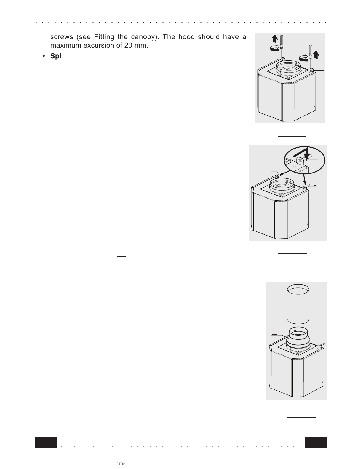
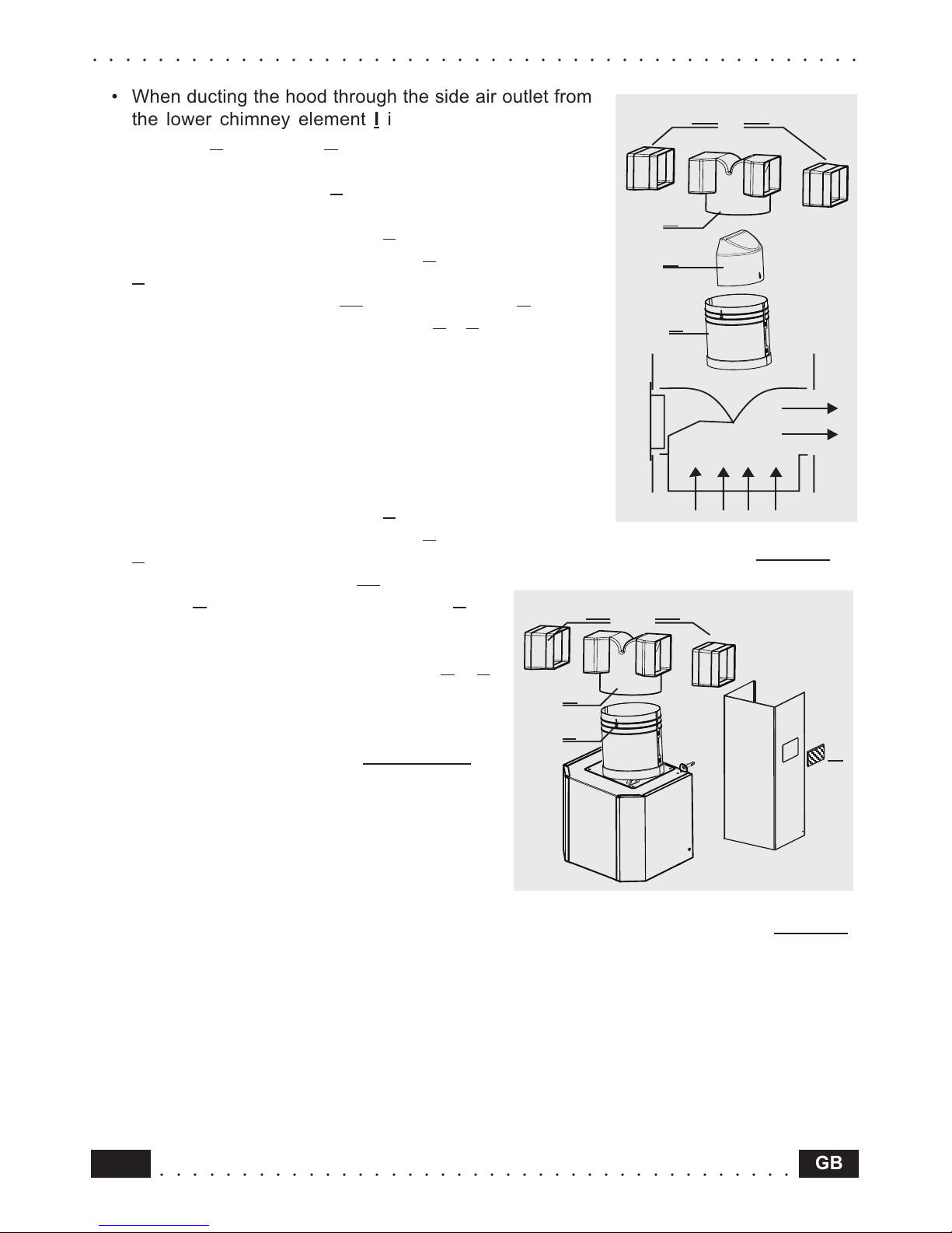
Ducting or Recirculation fitting
• Ducting fitting
• The hood can be ducted to the outside using either rigid or flexible
ducting Ø 120 or 150 mm, the choice of which is left to the installer.
When 120 mm ducting is to be used it will be necessary to install
the reduction flange item A on the air outlet (fig.5).
S1
S1
S1
S1