UPOWER ULB-5120MT User manual

EN Version:V1.0
Upower Electric Co.,Ltd
User Manual
ULB-5120MT


Content
1 Notes on this Manual································································································································································· 1
1.1 Target Group·····································································································································································1
1.2 Symbols Used·································································································································································1
2 Safety······································································································································································································2
2.1 Important Safety Instructions······························································································································2
2.2 Explanation of Symbols
··········································································································································3
2.3 Emergency situation ················································································································································· 4
3 Introduction
·························································································································································································5
3.1 Scope of application
···················································································································································5
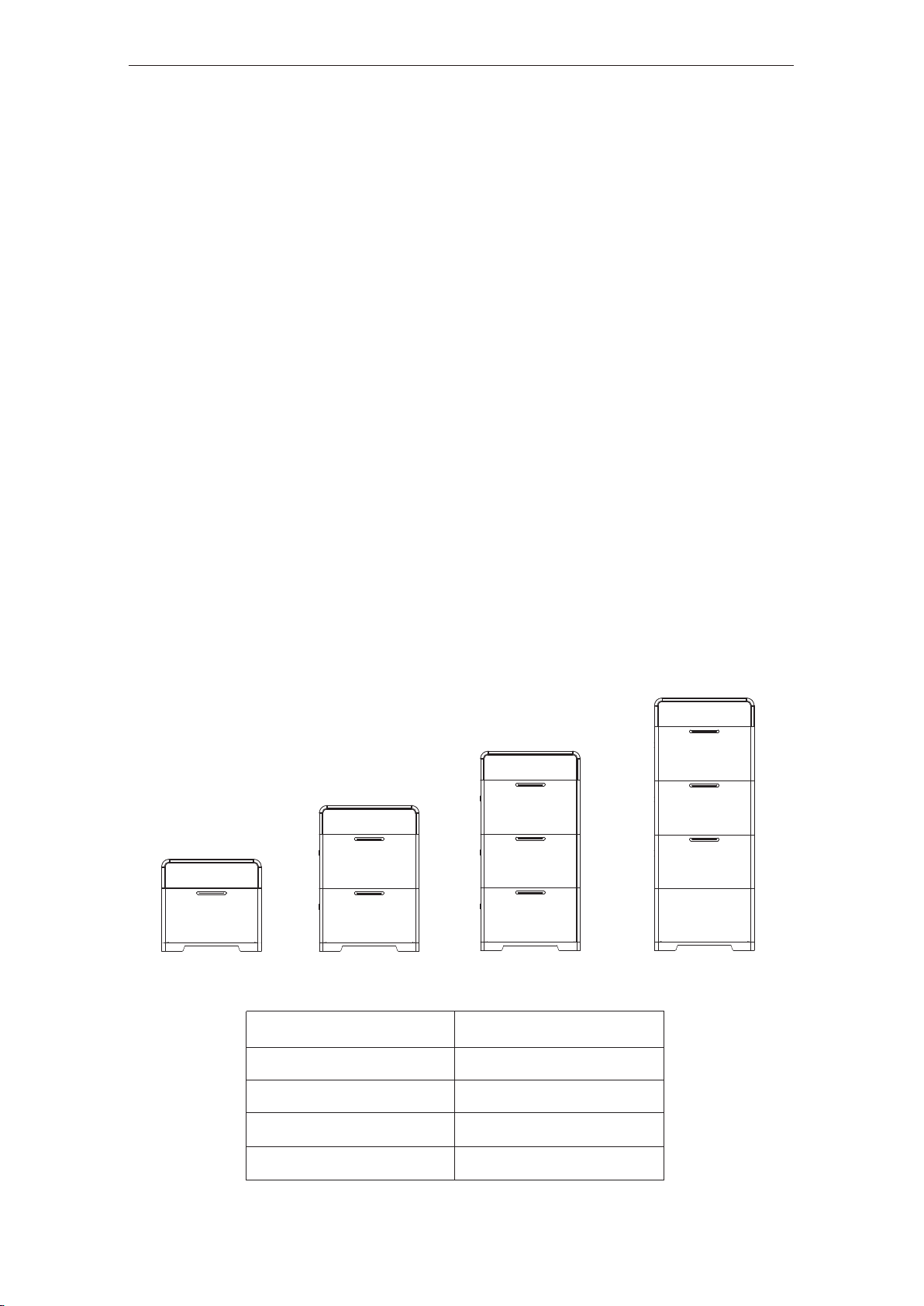
3.2 Product Model Description····································································································································6
3.3 Datasheet
···········································································································································································6
4 Installation Instructions····························································································································································7
4.1 Safety Tips ·········································································································································································7
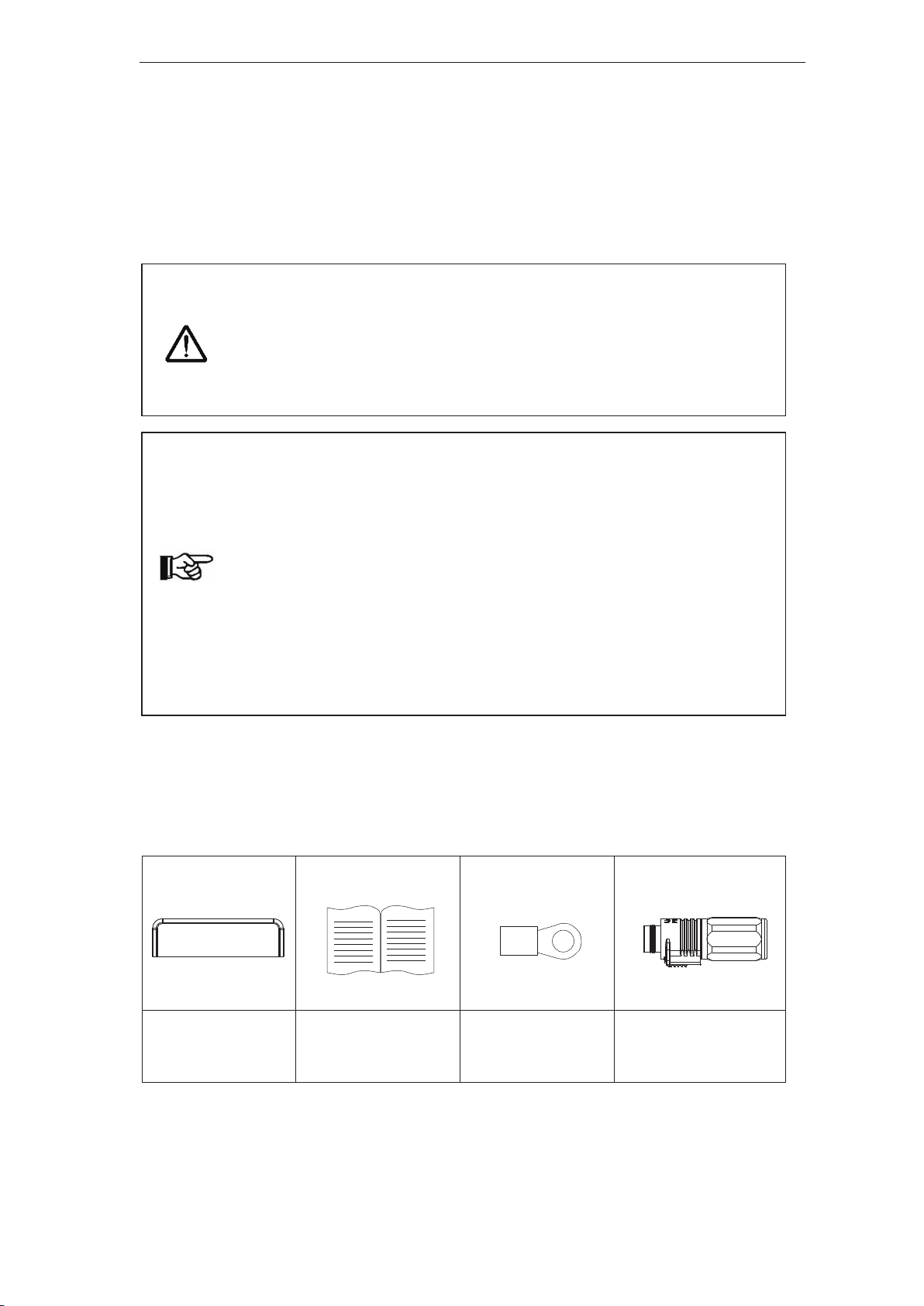
4.2 Packing List ······································································································································································7
4.3 Determine the installation method and location ·················································································9
4.4 Preparations before installation
·····················································································································12
4.5 Installation steps for storage unit··················································································································14
5 Electrical Connections···························································································································································17
5.1 Electrical Interface Description
·······················································································································17
5.1.1 Battery Control Box interface description
···············································································17
5.1.2 Battery interface description
·············································································································17
5.1.3 Base interface description
··················································································································18
5.2 System Wiring Schematic
···································································································································18
5.2.1 As a UHome expansion battery
····································································································· 18
5.2.2 Connect other low-voltage inverters
·························································································· 19
5.3 Battery Wiring
······························································································································································ 20
5.3.1 Battery wiring (Battery does not expand)
···············································································20
5.3.2 Connect the inverter
································································································································22
5.3.3 Grounding wire connection ···············································································································24
5.3.4 Side protection cover installation
··································································································24
6 LED indication··············································································································································································25
6.1 Bat LED
··································································································································································25
7 Battery Maintenance·······························································································································································26
7.1 Transportation
······························································································································································ 26
7.2 Storage
··············································································································································································26
7.3 Cleanliness ···································································································································································· 27
Low Voltage Storage Battery System User Manual

1 Notes on this Manual
1.1 Target Group
This manual is for qualified electricians. The tasks described in this manual
only can be performed by qualified personnel.
1.2 Symbols Used
The following types of safety instructions and general information appear in
this document as described below:
Danger
Danger!
Warning!
Caution!
Note!
“Danger” indicates a hazardous situation which, if not avoided, will
result in death or serious injury.
Warning
“Warning” indicates a hazardous situation which, if not avoided,
could result in death or serious injury.
Caution
“Caution” indicates a hazardous situation which, if not avoided, could
result in minor or moderate injury.
“Note” provides tips that are valuable for the optimal operation of our
product.
Low Voltage Storage Battery System User Manual
1

2 Safety
2.1 Important Safety Instructions
Danger!
Electric shock and high voltage.
● Do not expose the storage unit to temperatures in excess of 45°C.
● Do not subject the storage unit to any strong force.
● Do not touch uninsulated cable termination.
● Do not soak the storage unit in water or expose it to moistur
e
environment.
● Do not touch the case of the storage unit when it is wet in case of
electric shock.
● Do not dispose of batteries in fire. The batteries may explode!
● Do not place the storage unit near a heat source, such as dire
ct
sunlight, a fireplace.
● Keep inflammable and explosive dang erous items or flames away
from the storage unit.
● Do not charge or discharge damaged storage unit.
Before performing any work on the storage unit, please disconne
ct
the storage unit from all voltage sources as described in this
document.
Warning!
● Installation, repair, recycling, and disposal of storage unit must be
performed by qualified personnel in accordance with national and
local standards and regulations.
● Risks of chemical burn electrolyte or toxic gases.
● Do not place heavy objects on the top of the system.
● Do not connect any un-dedicated battery pack to UHome storage
unit.
● If the moisture penetrates the system (e.g., due to casing
damage), please do not install or operate the system.
Do not use wet hands to touch the system.
● Any behavior to change the functionality of the product without
permission will cause fatal injury to the operator, third parties, and
equipment. UHome is not responsible for these losses and
warranty claims.
● To ensure property and
personal safety, the batteries and inverter
shall be well grounded.
Low Voltage Storage Battery System User Manual
2
Danger
Warning

!
Caution!
● Do not modify or tamper with storage unit and other components
of
the system.
● Risk of injury by hoisting or falling system
● Batteries are heavy and personal injury can be caused if the
battery is improperly lifted or dropped during transport or improper
operation when attached or removed from walls. Lifting and moved
the products shall be conducted by more than one person.
Note
● Do not extend other brands of batteries at the battery port.
2.2 Explanation of Symbols
This section explains all the symbols shown on the inverter and on the type
label.
Dangerous electrical voltage
All work to the battery shall only be carried out by qualified personnel.
No open flames
Do not place or install near flammable or explosive materials.
Corrosive substance
Keep the machine away from corrosive substance.
Attention
Install the product out of reach of children
Danger of hot surface
The components inside the device will release a lot of heat during
operation. Do not touch metal plate housing of the machine during
operating.
Danger.
Risk of electric shock!
An error occurred
Read the usage manual to troubleshoot problems
This device SHALL NOT be disposed of in residential waste
Please go to Chapter Seven “Battery maintenance” for proper
treatment.
Recyclable
Low Voltage Storage Battery System User Manual
3
Caution

2.3 Emergency situation
Despite of its careful and professional protection design against any hazard
results, damage of the battery may still occur. If a small amount of battery
electrolyte is released due to a serious damage of the outer casing; or if the
battery explodes due to not being treated timely after a fire breaks out nearby,
and leaks out poisonous gases such as carbon monoxide, carbon dioxide etc.,
the following actions are recommended:
1) Eye contact: Rinse eyes with a large amount of running water and seek
medical advice
2) Contact with skin: Wash the contacted area with soap thoroughly and
seek medical advice
3) Inhalation: If you feel discomfort, dizziness or vomiting, seek medical
advice immediately.
4) Use a FM-200 or Carbon Dioxide (CO2) fire extinguishers to extinguish
the fire if there is a fire in the area where the battery pack is installed.
Wear a gas mask and avoid inhaling toxic gases and harmful substances
produced by the fire.
5) Use an ABC fire extinguisher, if the fire is not caused by battery and not
spread to it yet.
Potential danger of damaged battery:
Chemical Hazard: Despite of its careful and professional protection design
against any hazard results, rupture of battery shall still occur due to
mechanical damage, internal pressure etc., and may result in a leakage of
battery electrolyte. The electrolyte is corrosive and flammable. When there is
fire, the toxic gases produced will cause skin and eyes irritation, and
discomfort after inhalation. Therefore:
1) Do not open damaged batteries.
2) Do not damage the battery again (shock, fall, trample, etc.).
3) Keep damaged batteries away from water (except to prevent an energy
storage system from catching fire).
Warning!
If a fire has just occurred, try to disconnect the battery circuit breaker an
d
cut off the power supply first, but only if you can do so without endangeri
ng
yourself.
If the battery is on fire, do not attempt to extinguish the fire and evacuate
the crowd immediately.
●
●
Low Voltage Storage Battery System User Manual
4

4) Do not expose the damaged battery to the sun to prevent internal heating
of the battery.
Electrical hazard: The reason of fire and explosion accidents in lithium
batteries is battery explosion. Here are the main factors of battery explosion:
1) Short circuit of battery. Short circuit will generate high heat inside battery,
resulting in partial electrolyte gasification, which will stretch the battery
shell. The temperature reaching ignition point of internal material will lead
to explosive combustion.
2) Overcharge of battery. Overcharge of battery may precipitate lithium
metal. If the shell is broken, it will come into direct contact with the air,
resulting in combustion. The electrolyte will be ignited at the same time,
resulting in strong flame, rapid expansion of gas and explosion.
3 Introduction
3.1 Scope of application
Quantity of Battery System Capacity
1 5.12kWh
2 10.24kWh
3 15.36kWh
4 20.48kWh
Low Voltage Storage Battery System User Manual
5
5kWh
10kWh
15kWh
20kWh

3.2 Product Model Description
ULB -5120 MT
①②③
①ULB is the name of the Battery Module section in the All-In-One Storage Unit.
②5120:5.12kWh /2560:2.56kWh/3580:3.58kWh.
③MT: Wall hanging.
3.3 Datasheet
Battery Module ULB-5120MT
Electrical Parameter
Battery Type LiFePO
4
Battery Capacity per Kit [Wh] 5120
Usable Energy [Wh] 4600
Rated Voltage [V] 51.2
Voltage range [V] 44.8-57.6
Max. Charging and Discharging Rate 1C
Depth Of Discharge [DOD] ≤90%
Cycle Life(25
℃
,0.5C) ≥6000 times,80%Capacity retention
General Data
Communication Mode RS485/CAN2.0
Operating Temperature Range 0~50°C (Charge)/-10~50°C(Discharge)
Storage Temperature Range -15°C~60°C
Cooling Method Natural Convection
Altitude <2000m
Ambient Humidity 0-100%non-condensing
Noise[dBA] <25
Ingress Protection IP65
Dimensions [H*W*D][mm] 675*200*365
Weight [kg] 53.6
Low Voltage Storage Battery System User Manual
6

4 Installation Instructions
4.1 Safety Tips
4.2 Packing List
Battery Control Box Packge list
Battery Control
Box * 1 PCS
1* User Manual1* Ground terminal
2* Battery + connection
terminals
Danger!
Potential fires and electric shocks that are life threatening.
Do not place any flammable or explosive materials beside storage unit.
Equipment connected to high-voltage power generation equipment mus
t
be performed by qualified personnel in compliance with national an
d
local standards and regulations.
Note!
The pollution level applicable to storage unit is Class II.
Inappropriate or inconsistent installation environment can shorten th
e
life of storage unit.
Do not install storage unit directly by exposing it under strong sunlight.
Please do not install in damp places.
The installation location must be well ventilated.
Storage unit (hereinafter also referred to as the master device) can be
used with one battery. If the battery capacity needs to be expanded,
please use ULB-5120MT (slave device), and maximum 4 batteries are
supported for the whole system.
●
●
●
●
●
●
●
●
●
Low Voltage Storage Battery System User Manual
7

2* Battery -
connection terminals 1*Waterproof terminal
4*Roundhead screws
M3*5
4*SEM screw M4*10
1*Qualified Certificate 1*Packing List
Storage Battery Module package list
1 * Battery
2*Fixed support rack
2*Expansion screw M6 4*Round head screws
M3*5
4*SEM screw M4*10 4*Guide Pin 1*Grounding Cable
1*Right side cover
1*Left side cover 1* Cable grommet 8*Countersunk screw
Low Voltage Storage Battery System User Manual
8
1*Qualified Certificate

1*Packing List
Battery Base package list
1 * Battery 4*Guide Pin 1*Grounding Cable
1*Qualified Certificate 1*Packing List
1* External positive connection
wire (The length is determined
according to the number of
stacked batteries)
4.3 Determine the installation method and location
Battery Control Box(mm):
Low Voltage Storage Battery System User Manual
9

Battery Base dimension(mm):
Storage unit is cooled by natural wind convection. It is recommended to install
in indoors or sheltered areas to avoid direct sunlight, rain and snow.
Low Voltage Storage Battery System User Manual
10
Battery dimension(mm):
60
300
675
675
365
200

.
Low Voltage Storage Battery System User Manual
11
Please ensure that the air at the installation point is circulated. Bad air ventilation will
affect the working performance of internal electronic components and shorten the
service life of storage unit.

The following sites are not allowed for installation:
within 600mm of any exit.
within 600mm of any vertical side of a window or building ventilation that
ventilates a habitable room.
in celling spaces.
in wall cavities or under stairways.
on roofs, except for were specially deemed suitable.
under access walkways.
sites where the freezing point is reached, like garages, carports or other
places.
places with plenty of salt.
flooded areas.
within 600mm of any hot water unit, air conditioning unit or any other
appliance associated with the pre-assembled integrated battery energy
storage system.
4.4 Preparations before installation
Step 1: Take out the Battery Control Box, battery and base from the packing
box.
Step 2: Preparation before base installation:
①Use screwdriver to loosen the 4 screws on the side of the terminal
●
●
●
●
●
●
●
●
●
●
Low Voltage Storage Battery System User Manual
12

Guide Pin
②Install the 4 positioning pins in the holes at the four corners of the
base, and tighten them with a flathead screwdriver.
Step 3: Preparations before battery installation:
①Use screwdriver to loosen the cover screws on both sides.
②Pass the upside-down hanging ear through the mounting hole of the
chassis, and fix it with screws. It needs to be adjusted later, so it does
not need to be tightened.
③Install the 4 positioning pins in the holes at the four corners of the
battery case, and tighten them with a flathead screwdriver.
Step 4: Preparations before Battery Control Box installation:
①Use screwdriver to loosen the fixing screws on the side cover and
remove the cover.
Low Voltage Storage Battery System User Manual
13
Guide Pin
Fixed support rack

4.5 Installation steps for storage unit
Step 1: Choose the installation location, place the base, adjust it to horizontal,
and the base is 10~20mm away from the wall.
Note
!
strength to fix the screws and bear the weight of battery.
●
Low Voltage Storage Battery System User Manual
14

Step 2: Stack the battery in sequence.
Step 3: Use a marker pen to draw a line in the hole of the wall fixture to
determine the position of the screw hole.
Low Voltage Storage Battery System User Manual
15

Step 4: Take down the battery in sequence.
Step 5: Use a percussion drill to drill holes marked in Step 3 and drive in
expansion screws.
Step 6: Stack the battery module in sequence, tighten the cascading fixing
screws, fix the screws and wall fixing parts on the wall with a wrench, adjust
the fixing bracket screws of the chassis, and adjust the distance between the
chassis andthe wall to an appropriate distance (10~20mm) rear locking screw.
Low Voltage Storage Battery System User Manual
16

5 Electrical Connections
5.1 Electrical Interface Description
5.1.1 Battery Control Box interface description
Object Description Object Description
1 Battery - 4 Battery signal port
2 Battery + 5 Battery Switch
3 Battery + 6 Grounding screw
5.1.2 Battery interface description
1
2
3
Low Voltage Storage Battery System User Manual
Low Voltage Storage Battery System
17
4
Table of contents
Other UPOWER Storage manuals
Popular Storage manuals by other brands

Forest garden
Forest garden LOG STORE manual

IBM
IBM TS2250 Setup, operator, and service guide

Integra
Integra HDR-1 instruction manual

Kingston Technology
Kingston Technology DataTraveler 4000 user manual

Maxtor
Maxtor Personal Storage 3000DV installation guide

Sony
Sony Memory Stick MSA-32A operating instructions

LaCie
LaCie Two Big eSATA & USB user manual

Hitachi
Hitachi Virtual Storage Platform G350 Site preparation guide

Imation
Imation NEXSAN E60 installation guide

Buffalo
Buffalo USB Hard Drive with Encryption HDS-PHU2... user manual

FieldServer
FieldServer FS-8700-16 instruction manual

Seagate
Seagate Barracuda ES Serial ATA product manual