Urban Archaeology One Madison User manual

ONE MADISON LED MIRROR — INSTALLATION INSTRUCTIONS 1 OF 5
INSTALLATION INSTRUCTIONS
WWW.URBANARCHAEOLOGY.COM
REV 07.26.18
Installation Instructions for One Madison LED Mirror
Item code # UA2582 BA
Input: 100-240VAC 1.2 A 50-60Hz
277VAC .5A 50-60Hz
(277VAC for North American only)
Important Safety Instructions
Read all instructions and save for the future.
Do not use attachments not recommended by the manufacturer.
Never use mirror with LED lighting if not operating properly.
Do not use outdoors.
No user-serviceable parts inside. However, if the LED strips inside
need to be replaced the back of the mirror is removable.
Installation Instructions
Prepare the Power Supply
1. The lighting inside the mirror is low-voltage LED lighting. It is powered by an LED driver that is connected to the building’s 110V power
supply. The driver provided is a 24V 100w 4amp driver, Mean Well HLG-100H-24 or equal.
2. The LED driver is remote, not inside the mirror frame, and must be located no more than 15’ from the mirror. If it is located above a
ceiling or behind a wall, the LED driver must be near an access panel making the driver accessible for inspection or repairs.
3. Power/supply connections to the LED driver must be made inside a junction box that can be enclosed.
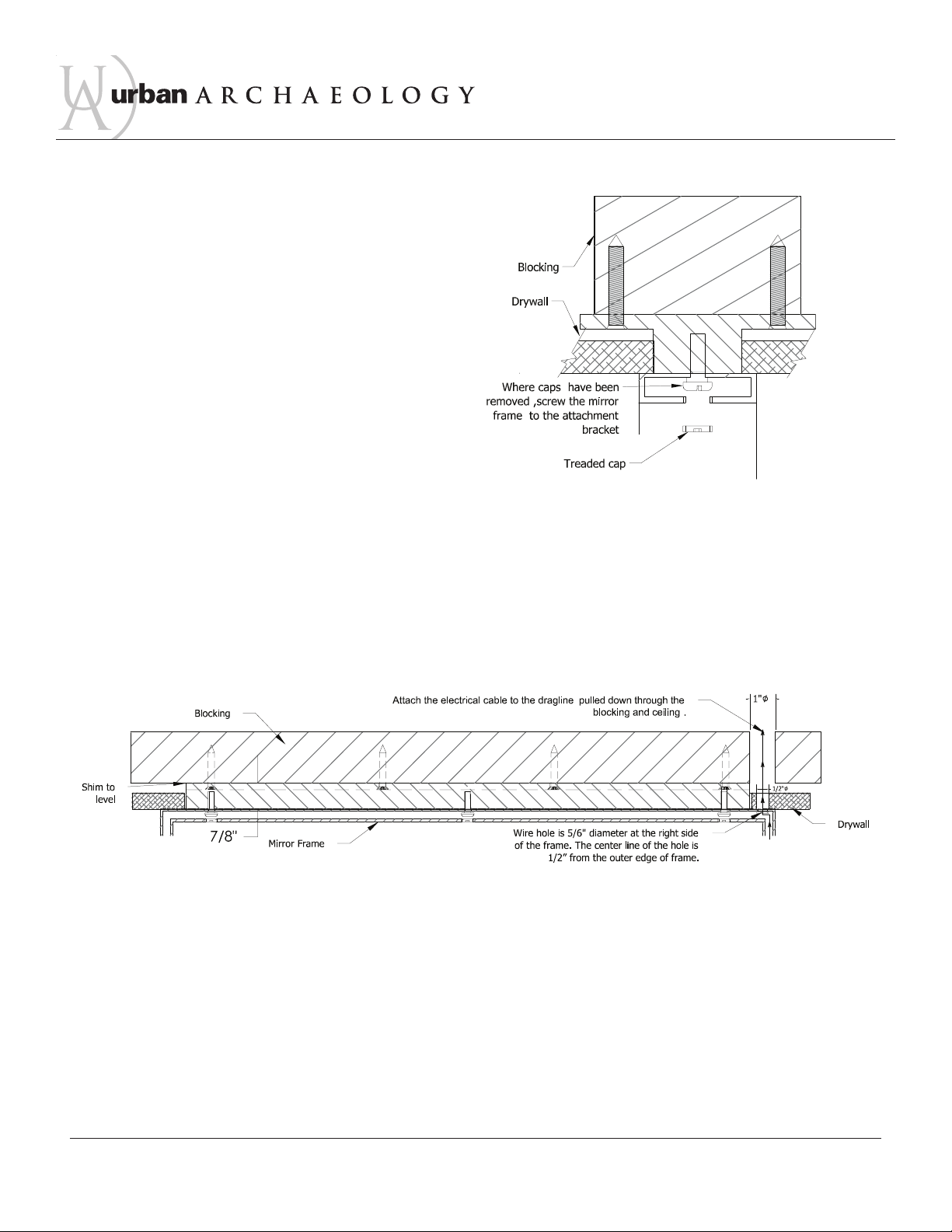
4. The mirror is supplied with 15 feet of 16/2 CL2P Plenum cable which is to be pulled to the location of the LED driver and connected.
The CL2P wire is rated to run above ceilings.
Prepare the blocking above ceiling (if mounting to a dropped ceiling)
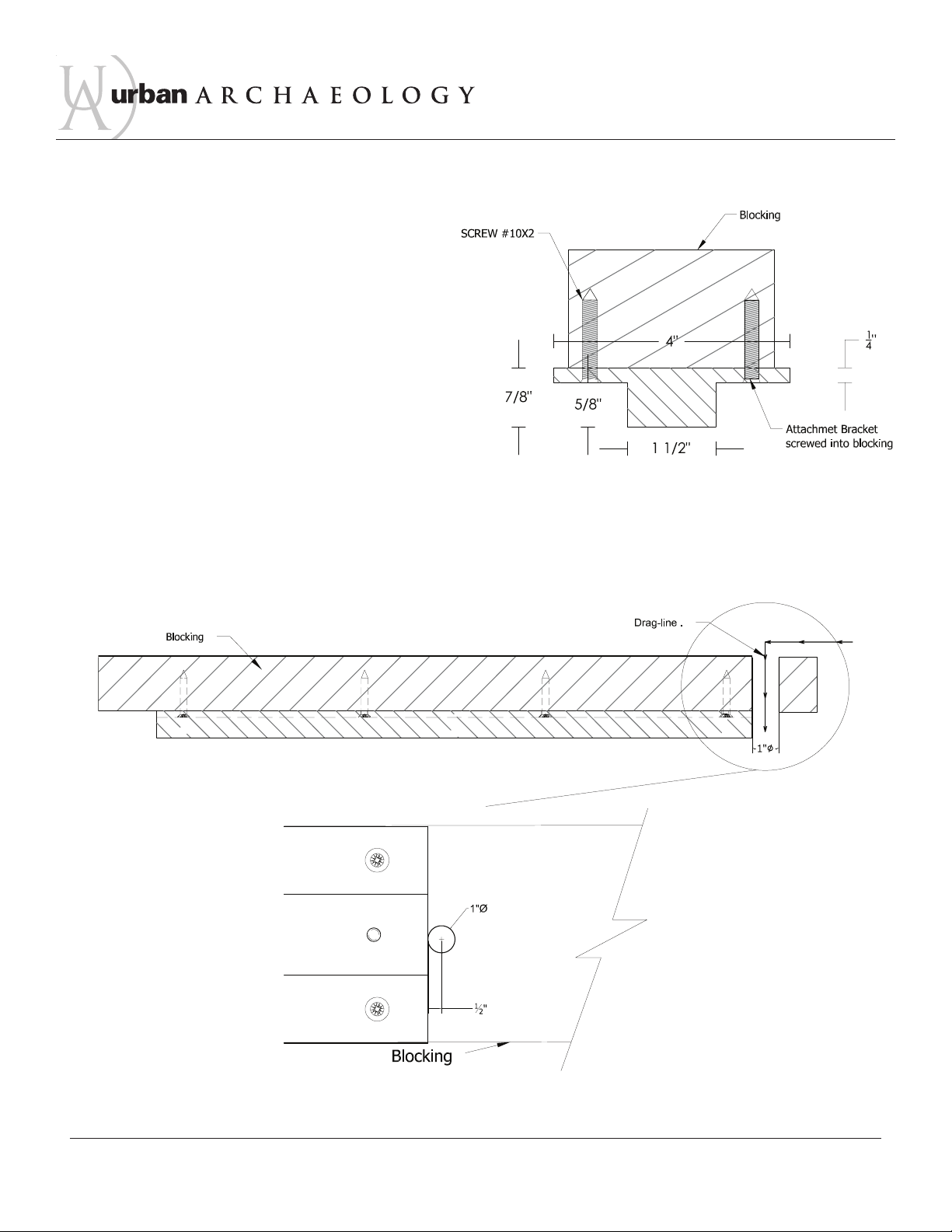
1. A steel ceiling attachment bracket is provided to be used for the installation of the mirror on a dropped ceiling. The bracket is intended
to make the suspended mirror rigid once installed.
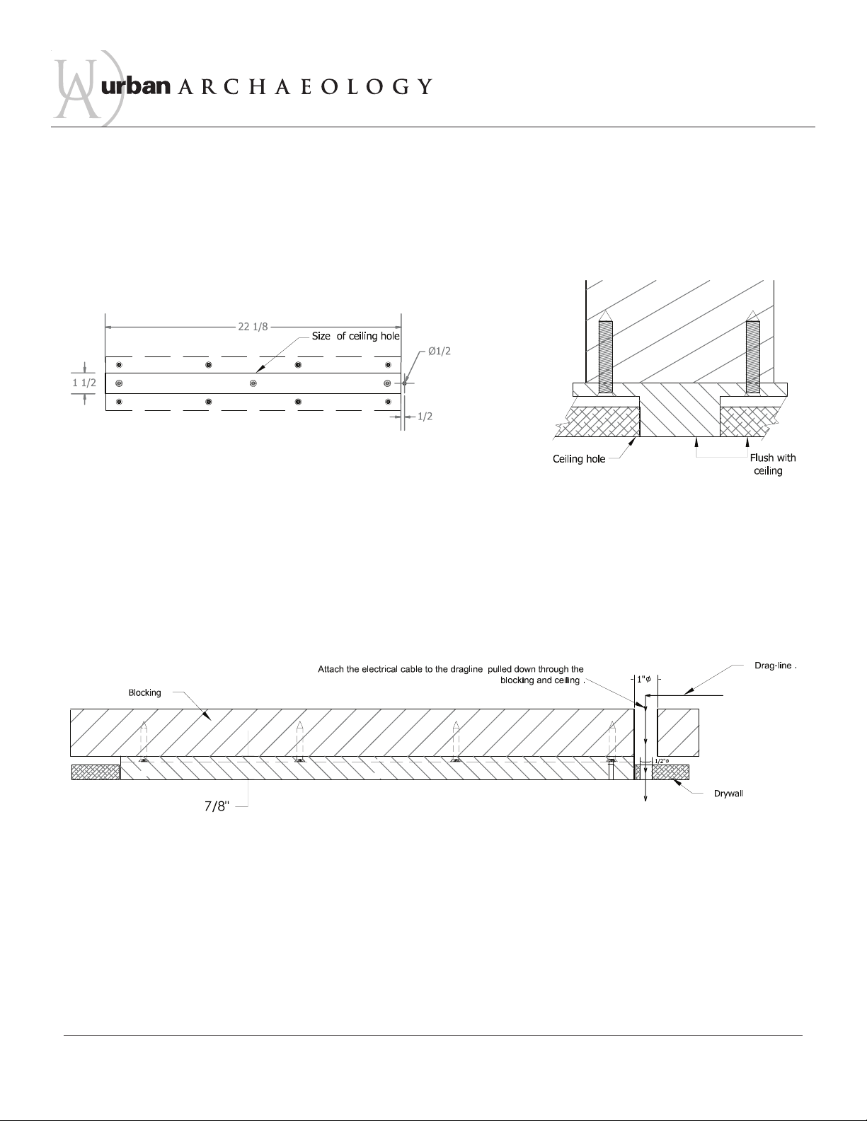
2. The attachment bracket will be screwed into blocking above the ceiling. (screws are provided) The blocking must be located at a height
that places the bottom of the bracket flush with the projected height of the finished ceiling. The blocking must be level and securely
attached to the structure above. The screws that are supplied, will go through predrilled holes at top of the mirror frame, the steel
bracket and then into the wood blocking.
Warning:
Risk of fire and electric shock if
improperly installed. Must be installed
by a licensed electrician according to
the instructions provided.
Caution:
Turn off power at main electrical box
prior to installation.

ONE MADISON LED MIRROR — INSTALLATION INSTRUCTIONS 2 OF 5
INSTALLATION INSTRUCTIONS
WWW.URBANARCHAEOLOGY.COM
Install the ceiling attachment bracket
1. Mount the attachment bracket to the blocking above the ceiling,
making sure that it’s level ( Fig.1). (Blocking must be secured to
structure so that it cannot move.)
2. While the area above the ceiling is still accessible, run a dragline from the mirror location to
the LED driver location. Drill a hole 1" diameter at the end of the attachment bracket where
the electric cable from mirror will come through. Pull the drag line down thru the hole in the
blocking (Fig.2 and Fig.3).
Fig. 1
Fig. 2
Bottom view detail
Fig. 3

ONE MADISON LED MIRROR — INSTALLATION INSTRUCTIONS 3 OF 5
INSTALLATION INSTRUCTIONS
WWW.URBANARCHAEOLOGY.COM
Install the ceiling
3. Cut a hole in the drywall ceiling to match the size of the bottom of the attachment
bracket (Fig.4). The bottom of the attachment bracket should be flush with the projected
ceiling height (Fig.5). Drill a 1/2" diameter hole in the ceiling aligned with the hole in the
blocking. Pull the drag line thru the ceiling hole.
Pull the wiring through the ceiling
4. The holes in the top of the mirror frame align with the holes in the attachment
bracket. There is also an exit hole in the top of the frame for the electric cable. With
two people holding the mirror in place. A third person will attach the electric cable to
the drag-line and push the cable up the holes in the ceiling and blocking (Fig.6).
Fig. 4
Fig. 5
Fig. 6

ONE MADISON LED MIRROR — INSTALLATION INSTRUCTIONS 4 OF 5
INSTALLATION INSTRUCTIONS
WWW.URBANARCHAEOLOGY.COM
Attachthe mirror frame
5. There are three threaded caps on the underside of the top of
the mirror frame. Unscrew these caps in order to access the screw
holes meant for attaching the frame to the attachment bracket.
DO NOT LOSE THESE CAPS (Fig.7).
6. Before finalizing the installation, make sure the mirror is perfectly level. If it is not, shims can
be installed above the bracket to level the mirror. Do not put shims between the mirror frame and
the drywall ceiling. The mirror frame is meant to be flush with the ceiling.
7. Once you have screwed the frame to the attachment bracket, replace the threaded caps to seal
the frame (Fig 8).
8. Pull the drag-line with the electric cable attached toward the driver and make the connections.
Fig. 7
Fig. 8

ONE MADISON LED MIRROR — INSTALLATION INSTRUCTIONS 5 OF 5
INSTALLATION INSTRUCTIONS
WWW.URBANARCHAEOLOGY.COM
Power Connections
1. Drag the cable from the mirror to the driver.
2. Make sure the power coming from the main electrical box is turned off.
3. Inside a junction box, connect the wires from the cable coming from the mirror to the output wires from the LED driver. Connect red wire to red
wire and black wire to black wire. Once the connection is complete, close the junction box.
4. Inside another junction box, connect the input wires on the LED driver to the line voltage wires coming from main power source. Once
connection is complete, close the junction box.
The LED lighting inside the mirror will be switched on / off at a wall switch provided by others.
Grounding Instructions
This product must be connected to a grounded metal, permanent wiring system, or an equipment-grounding conductor must be run with the circuit
conductors and connected to the equipment-grounding terminal or lead on the product.
User-maintenance Instructions
When cleaning the mirror or frame, do not use any abrasive products. Since the mirror frame is suspended from the ceiling, hold the frame in one
hand to prevent movement while wiping the mirror.
Use Nevr-Dull or equal metal cleaner to clean the frame, following the manufacturer’s instructions.
This manual suits for next models
1
Table of contents
Popular Personal Care Product manuals by other brands

Orliman
Orliman THERMOMED SMART 4201 Use and maintenance instructions

Evolution
Evolution Xpresso manual

Revamp
Revamp PROGLOSS ST-1600 Instruction manual and warranty information

Sunbeam
Sunbeam Rest & Relieve Therapeutic Mattress Pad user manual

Pivot
Pivot Nudge 1.0 quick guide

iRESTORE
iRESTORE Professional 282 user manual